Table of Contents
Advertisement
SERVICE MANUAL
HCD-D590, HCD-XB4 is the tuner, deck,
CD and amplifier section in LBT-D590,
LBT-XB4.
For the U.S. model
AUDIO POWER SPECIFICATIONS
POWER OUTPUT AND TOTAL HARMONIC DISTORTION:
With 8 ohm loads, both channels driven, from 70-20,000 Hz; rated 100 watts
per channel minimum RMS power, with no more than 0.9 % total harmonic
distortion from 250 milliwatts to rated output.
Amplifier section
Continuous RMS power output
(HCD-D590)
Canadian model:
(HCD-XB4)
Peak music power output
(HCD-XB4)
MICROFILM
HCD-D590/XB4
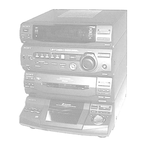
Photo: HCD-D590
SPECIFICATIONS
100+100 watts
(8 ohms at 1 kHz, 5%)
80+80 watts
(5 ohms at 1kHz, 10% THD)
1200 watts
Model Name Using Similar Mechanism
CD Mechanism Type
CD
Section
Base Unit Name
Optical Pick-up Name
Model Name Using Similar Mechanism
Tape deck
Section
Tape Transport Mechanism Type
Inputs
PHONO IN (phono jack):
VIDEO (AUDIO) IN (phono jack):sensitivity 250 mV, impedance 47 kilohms
MIX MIC (phono jack):
Outputs
PHONES (stereo phone jack):
SPEAKER:
(HCD-D590)
(HCD-XB4)
SURROUND SPEAKER:
(HCD-D590)
COMPACT DISC DECK RECEIVER
US Model
Canadian Model
HCD-D590
E Model
Australian Model
PX Model
HCD-XB4
NEW
CDM37L-5BD29AL
BU-5BD29AL
KSS-213D/Q-NP
HCD-H881
TCM-220WR2
sensitivity 3 mV, impedance 47 kilohms
sensitivity 1 mV, impedance 10 kilohms
accepts headphones of 8 odms or more
accepts impeadance of 8 to 16 ohms.
accepts impeadance of 5 to 16 ohms.
accepts impeadance of 16 ohms.
– Continued on next page –
Advertisement
Table of Contents

Related Manuals for Sony HCD-XB4


Summary of Contents for Sony HCD-XB4
- Page 1 SERVICE MANUAL US Model Canadian Model HCD-D590 E Model Australian Model PX Model HCD-XB4 HCD-D590, HCD-XB4 is the tuner, deck, CD and amplifier section in LBT-D590, Photo: HCD-D590 LBT-XB4. Model Name Using Similar Mechanism CD Mechanism Type CDM37L-5BD29AL Section Base Unit Name...
- Page 2 4-track 2-channel stereo Frequency response (DOLBY NR OFF) Supplied accessories: AM loop antenna (1) 60 - 13,000 Hz (±3 dB), using a Sony Remote RM-SD70 (1) TYPE I cassette Sony SUM-3 (NS) 60 - 14,000 Hz (±3 dB), using a Sony...
- Page 3 SONY PARTS WHOSE PART NUMBERS APPEAR AS DE FONCTIONNEMENT. NE REMPLACER CES COM- SHOWN IN THIS MANUAL OR IN SUPPLEMENTS PUB- POSANTS QUE PAR DES PIÈCES SONY DONT LES LISHED BY SONY. NUMÉROS SONT DONNÉS DANS CE MANUEL OU DANS LES SUPPLÉMENTS PUBLIÉS PAR SONY.
-
Page 4: Table Of Contents
TABLE OF CONTENTS SERVICING NOTES NOTES ON HANDLING THE OPTICAL PICK-UP GENERAL BLOCK OR BASE UNIT Getting Started ..............The laser diode in the optical pick-up block may suffer electrostatic Basic Operations ............... break-down because of the potential difference generated by the The CD Player .............. - Page 5 SECTION 1 This section is extracted from instruction manual. GENERAL – 5 –...
- Page 6 – 6 –...
- Page 7 – 7 –...
- Page 8 – 8 –...
- Page 9 – 9 –...
- Page 10 – 10 –...
- Page 11 – 11 –...
- Page 12 – 12 –...
- Page 13 – 13 –...
- Page 14 – 14 –...
- Page 15 – 15 –...
- Page 16 – 16 –...
- Page 17 – 17 –...
- Page 18 – 18 –...
- Page 19 – 19 –...
- Page 20 – 20 –...
- Page 21 SECTION 2 DISASSEMBLY • This set can be disassembled in the order shown below. FRONT PANEL CD MECHANISM OPTICAL MAIN BASE UNIT BD BOARD CASE SECTION PICK-UP SECTION DECK SECTION (Page 26) (Page 27) (Page 21) (Page 22) (Page 27) (Page 23) (Page 23) SLED...
- Page 22 FRONT PANEL SECTION 1 three frat wires (CN102, 205, 206) 3 front panel section 2 four screws (BVTP 3 × 8) MAIN BOARD 6 back panel 5 power cord 4 ereven screws (BVTP 3 × 8) 3 connector (CN901) 1 two flat wires (CN1, 202) 9 MAIN board IC201...
- Page 23 1 flat wire (CN202) MAIN SECTION 2 connector (CN203) 4 main section 3 two screws (BVTP 3 × 8) 3 screw (BVTP 3 × 8) 3 two screws (BVTP 3 × 8) CD MECHANISM DECK SECTION 3 five screws (BVTP 3 × 8) 4 CD mechanism deck section 2 flat wire...
- Page 24 TAPE MECHANISM DECK SECTION 4 three screws 4 three screws (BVTP 2.6 × 8) (BVTP 2.6 × 8) 5 Remove the tape mechanism deck section to direction of the arrow A . 3 two flat wires (CN601, 1001) 2 Open the cassette lids.
- Page 25 CD LID ASS’Y SECTION 6 four screws (BVTP 2.6 × 8) 5 connector (CN671) 7 CD lid ass’y 4 connector (CN661) 2 four screws (BVTP 2.6 × 8) 3 CD-B1 SW board 1 connector (CN642) PANEL (A) / (B) SUB ASS’Y 1 connector (CN612) 3 two claws...
- Page 26 BASE UNIT 3 base unit 1 yoke bracket 2 boss DISC TABLE Note: When the disc table is installed, adjust the positions of roller cam and mark z as shown in the figure, then set to the groove of disc table. 3 step screw 1 screw (BVTP 3 ×...
- Page 27 BD BOARD 1 two screws (PTPWH M2.6 × 6) 1 two screws (PTPWH M2.6 × 6) 2 optical pick-up section 3 two springs 3 two springs 5 screw (BVTP 2.6 × 8) 4 flat wire (CN101) 6 Removal the four solders. 7 BD board limit switch OPTICAL PICK-UP, SLED MOTOR...
- Page 28 AUDIO BOARD 2 two rivets 1 connector (CN651) 4 four screws (BTP 2.6 × 4) 3 Break the soldering of two flexible flat cables. 5 MD board CAPSTAN MOTOR 2 two screws 4 Removal the capstan motor (BTP 2.6 × 8) to direction of the arrow.
- Page 29 SECTION 3 TEST MODE [MC Cold Reset] [Change-over of AM Tuner Step between 9kHz and 10kHz] • The cold reset clears all data including preset data stored in the • A step of AM channels can be changed over between 9kHz and RAM to initial conditions.
-
Page 30: The Tape Deck
8. To exit from the aging mode, press POWER button to turn [Aging Mode] the set OFF. This mode can be used for operation check of CD section and tape deck section. • If an error occurred: 2-2. Operation during Aging Mode In the aging mode, the program is executed in the following se- The aging operation stops. -
Page 31: Test Mode
SECTION 4 SECTION 5 MECHANISM ADJUSTMENTS ELECTRICAL ADJUSTMENTS PRECAUTION DECK SECTION 0dB=0.775V 1. Clean the following parts with a denatured-alcohol-moistened swab: 1. Demagnetize the record/playback head with a head demagne- record/playback head pinch roller tizer. (Do not bring the head demagnetizer close to the erase erase head rubber belts head.) - Page 32 2. Turn the adjustment screw and check output peaks. If the peaks Tape Speed Adjustment DECK A do not match for L-CH and R-CH, turn the adjustment screw Note: Start the Tape Speed adjustment as below after setting to the so that outputs match within 1dB of peak.
- Page 33 Adjustable limits: Record bias Current Adjustment DECK B CN207 PB level: 47.3 to 53.1 mV (–24.3 to –23.3 dB) Procedure: Adjustment Location: main board 1. Mode: record [MAIN BOARD] (Component Side) Pin 6 (L-CH) of IC1501 on the main board. Pin #¶...
-
Page 34: Tuner Section
TUNER SECTION 0dB=1µV Note: As a front-end (FE1) is difficult to repair if faulty, replace it with new one. AM Section Adjustment Setting: loop antenna loop antenna (Supplied accessories) AM RF SSG 30% amplitude modulation by AM ANTENNA 60 cm 400 Hz signal terminal (TM1) Field strength dB ( µ... -
Page 35: Cd Section
S Curve Check CD SECTION oscilloscope Note: BD board 1. CD Block is basically designed to operate without adjustment. Therefore, check each item in order given. TP (FEO) 2. Use YEDS-18 disc (3-702-101-01) unless otherwise indicated. – TP (VC) 3. Use an oscilloscope with more than 10M impedance. 4. - Page 36 Adjustment Location: E-F Balance (1 Track Jump) check (Without remote commander) [BD BOARD] (Conductor Side) oscilloscope BD board TP (TEO) TP (VC) – IC101 Procedure: 1. Connect oscilloscope to test point TP (TEO) on BD board. 2. Turned Power switch on. 3.
- Page 37 SECTION 6 DIAGRAMS • Circuit Board Location TRANS board TCB board PANEL board MAIN board HEADPHONE-MIC board TC-A SW board POWER AMP board LED board CD-A SW board TC-B SW board CD-B1 SW board DOOR SW board CD-B2 SW board MOTOR board LEAF SWITCH board...
- Page 38 • Waveforms — BD Section— 1 IC101 #£ pin (PLAY MODE) 6 IC103 ^™ pin (RFCK) !¡ IC301 !£ pin (XT2) Approx. 1.3 Vp-p 4.6 Vp-p 31.3 µsec 7 IC103 &¢ pin (WFCK) 2 IC101 2 pin (FEI) (PLAY MODE) —...
-
Page 39: Block Diagrams
HCD-D590/XB4 6-1. BLOCK DIAGRAMS – TUNER SECTION – ST +10V MPX IN AM / FM FM FRONT END ANTENNA AMP IN L OUT L 10.7MHz 10.7MHz FM 75Ω IF AMP IF AMP ANT IN IF OUT FM IN Q1,2 Q3,4 OUT R FM / AM MPX MAIN SECTION... - Page 40 HCD-D590/XB4 – CD SECTION – - CD SECTION - OPTICAL PICK-UP BLOCK DETECTOR MAIN C,OUT CNIN LOUT1 SECTION SENS1 SEIN (page 41) IC103 DIGITAL SIGNAL PROCESSOR DATA DATAO XLTO LOUT2 R-CH CLKO LOCK LOCK FE-O FE-M 21 27 12 11 TA-M TA-O S101...
-
Page 41: Main Section
HCD-D590/XB4 – MAIN SECTION – - MAIN SECTION - IC231 J761 R-CH SPEANA MIX J760 IC760 (1 / 2) IC760 (2 / 2) PHONES RV706 MIC AMP MIC AMP IC101 MIC LEVEL – J101 (1 / 2) PHONO PHONO L-CH IC102 INPUT SELECTOR IC801 POWER AMP... - Page 56 • IC Block Diagrams –BD Section – IC102 BA5941FP IC101 CXA1992AR – – + – + – RF SUMMING PD2 IV PD1 IV FE_BIAS SENS2 LEVEL SHIFT – ↓ SENS1 LASER POWER CONTROL LEVEL SHIFT F IV AMP FE AMP C.
- Page 57 – TUNER section – IC1 LC72130 PHASE DETECTOR CHARGE PUMP UNLOCK POWER DETECTOR RESET REFERENCE SWALLOW COUNTER DIVIDER 1/16, 1/17 4BITS 12BITS PROGRAMMABLE DRIVER UNIVERSAL DATA SHIFT REGISTER LATCH COUNTER 3 4 5 6 IC2 LA1835 17 16 DECODER RF. AMP ANTI BIRDIE BUFF STEREO...
-
Page 58: Ic Pin Function Description
6-16. IC PIN FUNCTION DESCRIPTION MAIN BOARD IC301 µPD780018Y (MAIN CONTROL) Pin No. Pin Name Function TA-MUTE Line mute signal output DBFB-H/L DBFB H/L select signal output 427-LT Latch signal output for IC201 (62427) KCON-LT Not used KCON-ON/OFF F-RELAY Front speaker relay control output R-RELAY Not used PL-RELAY... - Page 59 Pin No. Pin Name Function COM-CLK Common serial clock output CD-POWER CD power on signal output CD-DATA CD data output CD-CLOK CD clock output MSM-CMD Not used MSM-BUSY Connected ground MSM-LT MSM-NAR Not used MSM-CH INPUT-CHANGE Not used 11C-DATA Data output for IC601 11C-CLK Clock output for IC601 XRST...
- Page 60 Pin No. Pin Name Function EQ-H/N Equalizer H/N select output BIAS Bias ON/OFF signal output REC-MUTE REC mute ON/OFF selection output NR-ON/OFF NR ON/OFF signal output R/P-PASS REC/PB/PASS selection output TC-MUTE TC mute ON/OFF selection output A-PLAY-SW Deck A play detect B-PLAY-SW Deck B play detect TC-RELAY...
- Page 61 PANEL BOARD IC601 TMP87CH74 (DISPLAY CONTROL) Pin No. Pin Name Function LED3-LED8 LED driver output – Ground X-OUT X’tall (8MHz) X-IN RESET Reset signal input from main controller LED 9 LED10 Connected ground TEST 14-19 LED11-LED19 LED driver output VOL-A Rotary encoder (S701 VOLUME) pulse input DOOR SW DOOR SW (S651) ON/OFF signal input...
-
Page 62: Exploded Views
SECTION 7 EXPLODED VIEWS NOTE: • -XX and -X mean standardized parts, so they • Items marked “*” are not stocked since they The components identified by mark ! or dotted line with mark ! are may have some difference from the original are seldom required for routine service. - Page 63 (2) FRONT PANEL SECTION-1 TCM-220WR2 supplied supplied supplied with S711 Ref. No. Part No. Description Remark Ref. No. Part No. Description Remark 4-987-995-01 SPRING (CD EJECT), COMPRESSION * 63 1-664-016-11 DOOR SW BOARD 4-987-001-01 BUTTON (EJECT CD) 4-987-038-01 LID, DISC * 53 1-664-009-11 CD-A SW BOARD * 65...
- Page 64 A-4392-477-A PANEL BOARD, COMPLETE 4-987-021-01 INDICATOR (TC A) 1-773-051-11 WIRE (FLAT TYPE) (17 CORE) 4-986-997-01 BUTTON (DECK.A) X-4947-962-1 BUTTON (TUNER) ASSY 4-963-404-21 EMBLEM (5-A), SONY 4-987-013-01 INDICATOR (TUNER) 4-973-644-01 KNOB (MIC) X-4947-968-1 BUTTON (WOOFER) ASSY 4-951-620-01 SCREW (2.6X8), +BVTP X-4947-967-1 BUTTON (DECK B) ASSY...
- Page 65 (4) CHASSIS SECTION not supplied E, AR, MX, PX E, MX, PX not supplied T901 CNP901 supplied CNP901 US, CND CDM37L-5BD29AL CNP901 CNP901 not supplied The components identified by Les composants identifiés par une mark ! or dotted line with marque ! sont critiques pour la mark ! are critical for safety.
- Page 66 (5) TAPE MECHANISM DECK SECTION-1 (TCM-220WR2) not supplied Ref. No. Part No. Description Remark Ref. No. Part No. Description Remark X-4947-943-1 HOLDER (L) ASSY, CASSETTE * 206 4-980-439-01 FULCRUM, HOLDER X-4947-944-1 HOLDER (R) ASSY, CASSETTE 3-354-957-01 JOINT (LOCK LEVER) 4-959-231-11 SPRING (L), TORSION 3-354-953-01 LEVER (LOCK LEVER L) 4-959-232-11 SPRING (R), TORSION 3-354-954-01 LEVER (LOCK LEVER R)
- Page 67 (6) TAPE MECHANISM DECK SECTION-2 (TCM-220WR2) (including r C) not supplied HP101 (including r A) not supplied not supplied HRPE101 (including r B) not supplied not supplied not supplied not supplied Ref. No. Part No. Description Remark Ref. No. Part No. Description Remark 3-908-560-01 SPRING, AZIMUTH ADJUSTMENT...
- Page 68 (7) TAPE MECHANISM DECK SECTION-3 (TCM-220WR2) r C : MOTOR board (Supplied with AUDIO board) not supplied Ref. No. Part No. Description Remark Ref. No. Part No. Description Remark 3-908-597-01 CAM (A) X-3370-171-1 FLYWHEEL (BR) ASSY 3-908-608-11 SCREW, STEP 3-908-600-01 LEVER (REV-B) X-3372-930-1 ARM (A) ASSY, FR * 316 1-650-669-11 LEAF SWITCH BOARD...
- Page 69 (8) CD MECHANISM DECK SECTION (CDM37L-5BD29AL) M201 BU-5BD29AL supplied Ref. No. Part No. Description Remark Ref. No. Part No. Description Remark 4-987-976-01 SCREW, STEP * 364 A-4673-765-A CD MOTOR BOARD, COMPLETE 4-944-490-01 BELT (TIMING) 4-978-426-01 INDICATOR (NO.) A-4660-978-A GEAR (PULLEY) ASSY * 366 1-659-059-13 BD LED BOARD 4-978-421-01 GEAR (MID)
- Page 70 (9) BASE UNIT SECTION (BU-5BD29AL) M101 (including r A) M102 Ref. No. Part No. Description Remark Ref. No. Part No. Description Remark ! 401 8-820-020-01 OPTICAL PICK-UP KSS-213D/Q-NP 4-917-564-01 GEAR (P), FLATNESS 1-769-069-11 WIRE (FLAT TYPE) (16 CORE) * 407 A-4699-522-A BD BOARD, COMPLETE 4-917-567-21 GEAR (M) 4-951-620-01 SCREW (2.6X8), +BVTP...
-
Page 71: Electrical Parts List
SECTION 8 AUDIO ELECTRICAL PARTS LIST NOTE: • Due to standardization, replacements in the • SEMICONDUCTORS The components identified by mark ! or dotted line with mark ! are In each case, u: µ, for example: parts list may be different from the parts speci- critical for safety. - Page 72 AUDIO Ref. No. Part No. Description Remark Ref. No. Part No. Description Remark R331 1-249-430-11 CARBON 1/4W C107 1-164-161-11 CERAMIC CHIP 0.0022uF 10% 100V R401 1-247-881-00 CARBON 120K 1/4W C108 1-164-232-11 CERAMIC CHIP 0.01uF R402 1-249-409-11 CARBON 1/4W C109 1-164-232-11 CERAMIC CHIP 0.01uF R403 1-249-433-11 CARBON...
- Page 73 Ref. No. Part No. Description Remark Ref. No. Part No. Description Remark C185 1-164-232-11 CERAMIC CHIP 0.01uF R128 1-216-098-00 METAL CHIP 110K 1/10W C188 1-163-235-11 CERAMIC CHIP 22PF R129 1-216-025-91 METAL GLAZE 1/10W R130 1-216-079-00 METAL CHIP 1/10W C189 1-163-235-11 CERAMIC CHIP 22PF R131 1-216-079-00 METAL CHIP...
- Page 74 BD LED CD MOTOR CD-A SW CD-B1 SW Ref. No. Part No. Description Remark Ref. No. Part No. Description Remark 1-659-059-13 BD LED BOARD < DIODE > ************ D641 8-719-058-04 DIODE SEL5223S-TP15 (NON-STOP) < DIODE > < RESISTOR > D201 8-719-032-98 DIODE SEL5820A R731 1-247-843-11 CARBON...
- Page 75 CD-B2 SW DOOR SW HEADPHONE-MIC LEAF SWITCH Ref. No. Part No. Description Remark Ref. No. Part No. Description Remark 1-664-011-11 CD-B2 SW BOARD C776 1-162-294-31 CERAMIC 0.001uF 10% C794 1-164-159-21 CERAMIC 0.1uF *************** C795 1-164-159-21 CERAMIC 0.1uF < RESISTOR > <...
- Page 76 LEAF SWITCH MAIN Ref. No. Part No. Description Remark Ref. No. Part No. Description Remark S1004 1-571-281-21 SWITCH, LEAF (A HALF) C202 1-136-169-00 FILM 0.22uF S1005 1-571-281-21 SWITCH, LEAF (A CrO2) C203 1-130-493-00 MYLAR 0.068uF 5% S1006 1-572-248-21 SWITCH, LEAF (REC A) C204 1-130-493-00 MYLAR 0.068uF 5%...
- Page 77 MAIN Ref. No. Part No. Description Remark Ref. No. Part No. Description Remark C310 1-102-514-11 CERAMIC 22PF < CONNECTOR > C311 1-164-159-21 CERAMIC 0.1uF C315 1-126-933-11 ELECT 100uF CN101 1-778-982-11 CONNECTOR, BOARD TO BOARD 13P C390 1-126-933-11 ELECT 100uF * CN102 1-568-836-11 SOCKET, CONNECTOR 17P C393 1-126-925-11 ELECT...
- Page 78 MAIN Ref. No. Part No. Description Remark Ref. No. Part No. Description Remark IC281 8-759-111-68 IC uPC1237HA < RESISTOR > IC301 8-759-459-31 IC uPD780018YGF-013-3BA R102 1-249-417-11 CARBON 1/4W IC302 8-759-635-63 IC M51943BSL R103 1-249-437-11 CARBON 1/4W IC901 8-759-288-53 IC LA5617 R104 1-249-417-11 CARBON 1/4W...
- Page 79 MAIN Ref. No. Part No. Description Remark Ref. No. Part No. Description Remark R227 1-249-441-11 CARBON 100K 1/4W R316 1-249-429-11 CARBON 1/4W R228 1-249-429-11 CARBON 1/4W R318 1-249-429-11 CARBON 1/4W R231 1-249-437-11 CARBON 1/4W R319 1-249-429-11 CARBON 1/4W R232 1-249-437-11 CARBON 1/4W R320 1-249-429-11 CARBON...
- Page 80 MAIN PANEL Ref. No. Part No. Description Remark Ref. No. Part No. Description Remark R917 1-247-815-91 CARBON 1/4W < TERMINAL > R918 1-249-425-11 CARBON 4.7K 1/4W TM131 1-537-240-31 TERMINAL BOARD (CHECKER PIN)(SPEAKER) R920 1-249-417-11 CARBON 1/4W TM132 1-537-240-31 TERMINAL BOARD (CHECKER PIN) R921 1-247-895-91 CARBON 470K...
- Page 81 PANEL Ref. No. Part No. Description Remark Ref. No. Part No. Description Remark CN602 1-506-486-11 PIN, CONNECTOR 7P Q610 8-729-119-77 TRANSISTOR 2SA1175-FEK * CN603 1-568-944-11 PIN, CONNECTOR 6P * CN604 1-568-946-11 PIN, CONNECTOR 8P Q611 8-729-119-77 TRANSISTOR 2SA1175-FEK Q614 8-729-119-77 TRANSISTOR 2SA1175-FEK <...
- Page 82 PANEL POWER AMP Ref. No. Part No. Description Remark Ref. No. Part No. Description Remark R657 1-249-418-11 CARBON 1.2K 1/4W S609 1-554-303-21 SWITCH, TACTILE (GROOVE) S610 1-554-303-21 SWITCH, TACTILE (GEQ ¢) R658 1-249-427-11 CARBON 6.8K 1/4W R659 1-247-815-91 CARBON 1/4W S611 1-554-303-21 SWITCH, TACTILE (GEQ ª) 1-554-303-21 SWITCH, TACTILE (GEQ ·)
- Page 83 POWER AMP Ref. No. Part No. Description Remark Ref. No. Part No. Description Remark C851 1-128-582-11 ELECT 10uF 100V R804 1-249-437-11 CARBON 1/4W (US, CND) R805 1-260-107-11 CARBON 4.7K 1/2W (US, CND) C851 1-126-963-11 ELECT 4.7uF (EXCEPT US, CND) R805 1-260-105-11 CARBON 3.3K 1/2W...
- Page 84 TC-A SW TC-B SW TABLE SENSOR Ref. No. Part No. Description Remark Ref. No. Part No. Description Remark 1-659-058-13 TABLE SENSOR BOARD D638 8-719-057-09 DIODE LNJ801LPDJA (r REC) ******************* < RESISTOR > 4-980-385-01 HOLDER (SW) R715 1-249-421-11 CARBON 2.2K 1/4W <...
- Page 85 Ref. No. Part No. Description Remark Ref. No. Part No. Description Remark 1-126-964-11 ELECT 10uF < DIODE > 1-164-159-21 CAP, CERAMIC 0.1uF 1-126-961-11 ELECT 2.2uF 8-719-933-33 DIODE UZL-6L1-TA 1-102-518-11 CERAMIC 33PF 8-719-987-63 DIODE 1N4148M-TA 1-162-294-31 CERAMIC 0.001uF 10% < FRONT END > 1-162-306-11 CERAMIC 0.01uF 1-126-933-11 ELECT...
- Page 86 TRANS Ref. No. Part No. Description Remark Ref. No. Part No. Description Remark 1-247-807-31 CARBON (SMALL) 100 1/4W < POWER CORD > 1-249-411-11 CARBON 1/4W 1-249-425-11 CARBON 4.7K 1/4W ! CNP901 1-558-943-41 CORD, POWER (E, MX, PX) 1-247-843-11 CARBON (SMALL) 3.3K 1/4W ! CNP901 1-575-042-21 CORD, POWER (US, CND) 1-249-417-11 CARBON...
- Page 87 (E, AR, MX, PX) 3-859-536-41 MANUAL, INSTRUCTION (CHINESE) (PX) 4-987-613-01 INDIVIDUAL CARTON (US) 4-987-615-01 INDIVIDUAL CARTON (AUS) 8-917-581-90 REMOCON, SONY RM-SD70//M SET The components identified by Les composants identifiés par une mark ! or dotted line with marque ! sont critiques pour la mark ! are critical for safety.
- Page 88 HCD-D590/XB4 Sony Corporation 97B057042-1 Printed in Singapore © 1997. 2 9-960-844-11 Home A&V Products Company Published by Service and Safety Engineering Dept. (Shibaura) – 112 –...