Advertisement
May 2002
CE-5(T)
SERVICE NOTES
Second Edition
Issued by RJA
SPECIFICATIONS............................................................. 2
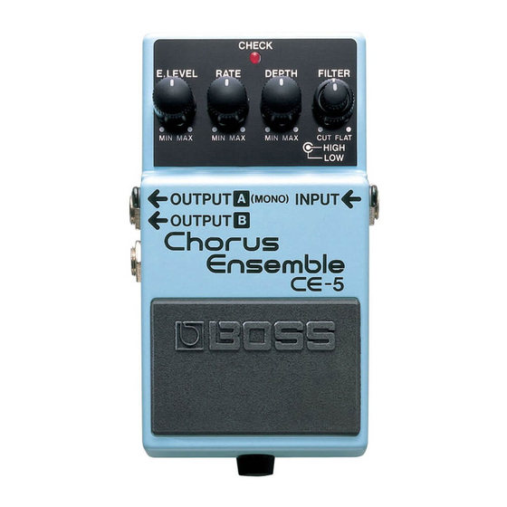
LOCATION OF CONTROLS,PARTS LIST ................... 3
EXPLODED VIEW,PARTS LIST ..................................... 4
PARTS LIST........................................................................ 5
THE INSPECTION METHOD ........................................ 8
CIRCUIT BOARD.............................................................. 9
CIRCUIT DIAGRAM...................................................... 10
WARNING
Due to an IC change, the parts have been changed from serial No. KP16600.
We call the new type of this model, CE-5A for identifying the old type and new
type for convenience on service system.
Although the model name will change from "CE-5" to "CE-5A", the product
pedal is still labeled "CE-5".
The appearance of "CE-5" and "CE-5A" are the same. Identify by the serial
number or the model name that is silk-screen printed on the board.
When referring to the service notes or ordering parts, check the model name
using the above process.
This service note is for "CE-5A". Refer to "CE-5 SERVICE NOTES"(#17059623)
when repairing "CE-5". Variable resistor, jack, switch and mechanical parts for
the "CE-5" and "CE-5A" are compatible.
Copyright © 2002 ROLAND CORPORATION
All rights reserved. No part of this publication may be reproduced in any form without the written permission
of ROLAND CORPORATION.
17059623E2
Printed in Japan (0800) (AS)
Advertisement

Related Manuals for Boss CE-5(T)


Summary of Contents for Boss CE-5(T)
-
Page 1: Table Of Contents
May 2002 CE-5(T) SERVICE NOTES Second Edition Issued by RJA SPECIFICATIONS............. 2 LOCATION OF CONTROLS,PARTS LIST ....3 EXPLODED VIEW,PARTS LIST ........4 PARTS LIST................ 5 THE INSPECTION METHOD ........8 CIRCUIT BOARD.............. 9 CIRCUIT DIAGRAM............10 WARNING Due to an IC change, the parts have been changed from serial No. KP16600. We call the new type of this model, CE-5A for identifying the old type and new type for convenience on service system. -
Page 2: Specifications
May 2002 SPECIFICATIONS Controls Pedal Switch Effect Level Modulation Rate Modulation Depth High Filter Low Filter Indicator Check Indicator (serves also as battery check indicator) Jacks Input Output A(MONO)/B AC Adaptor Input Impedance 1 M ohm Output Impedance 1 k ohm Recommended Load Impedance 10 k ohm or greater Residual Noise... -
Page 3: Location Of Controls,Parts List
CE-5(T) LOCATION OF CONTROLS,PARTS LIST fig.panel PART CODE PART NAME DESCRIPTION 13449711 AC ADAPTOR JACK HEC-0470-01-630 2253753801 PSA CAUTION 253-538 22480260 ROUND KNOB PR KNOB MF BLK/LCG 13289155 POTENTIOMETER (E.LEVEL, RATE) RK0971110 250KC 22480260 ROUND KNOB PR KNOB MF BLK/LCG 13289154 POTENTIOMETER (DEPTH) RK09711100K4A 100KB... -
Page 4: Exploded View,Parts List
May 2002 EXPLODED VIEW,PARTS LIST fig.explo [PARTS] PART CODE PART NAME DESCRIPTION Q’TY 13129710 SWITCH (PUSH) JM-0404 2226733300 CUSHION 226-333 F3419102 BATTERY CONNECTOR G253751603 BOTTOM CAUTION PSA FCC/CE/C-TICK/EMC GRY 2235730500 BOTTOM BASE 235-305 2202785100 BOTTOM COVER 202-851 2216756000 INSULATION SPACER 2215770201 PEDAL GUIDE BUSH 215-702... -
Page 5: Parts List
CE-5(T) PARTS LIST fig.part1e CONSIDERATION ON PARTS ORDRING SAFETY PRECAUTIONS: When ordering any parts listed in the parts list, please specify the following items in the order sheet. The parts marked have PART NUMBER DESCRIPTION MODEL NUMBER safety-related characteristics. Use 22575241 Sharp Key C-20/50... - Page 6 May 2002 RESISTOR 00567323 RPC05T 223 J MTL.FILM RESISTOR 00567456 RPC05T 224 J MTL.FILM RESISTOR 00567334 RPC05T 273 J MTL.FILM RESISTOR R4,R8 00567345 RPC05T 333 J MTL.FILM RESISTOR R36,R52,R65 00567112 RPC05T 471 J MTL.FILM RESISTOR 00567245 RPC05T 472 J MTL.FILM RESISTOR R49,R51 00567378 RPC05T 473 J...
- Page 7 CE-5(T) ACCESSORIES (Standard) 2604776702 OWNER’S MANUAL ENGLISH ******** BATTERY MANGANESE...
-
Page 8: The Inspection Method
May 2002 THE INSPECTION METHOD Output waveform check Connect an oscillator to the INPUT jack, and input test signal. Connect an oscilloscope to the OUTPUT A jack. Check that the minimum and maximum values for the delay time are as follows. fig.check1 INPUT SET CONTROLS... -
Page 9: Circuit Board
CE-5(T) CIRCUIT BOARD fig.circit View from component side fig.circit View from foil side... -
Page 10: Circuit Diagram
May 2002 CIRCUIT DIAGRAM fig.circit...