Table of Contents
Advertisement
Available languages
Available languages
Advertisement
Table of Contents

Related Manuals for Peavey XR 600F


Summary of Contents for Peavey XR 600F
- Page 1 ® ’ W N E R A N U A L...
- Page 2 Intended to alert the user to the presence of uninsulated “dangerous voltage” within the product’s enclosure that may be of sufficient magnitude to constitute a risk of electric shock to persons. Intended to alert the user of the presence of important operating and maintenance (servicing) instructions in the literature accompanying the product.
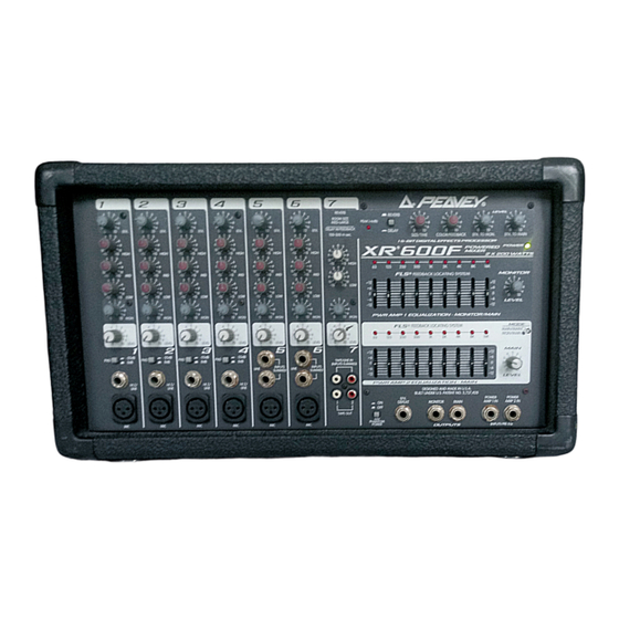
- Page 3 The master section features a unique graphic equalizer/power amp mode switch. Without patching, the XR 600F can be used as a mixer/amplifier for the mains (default). This mode utilizes both EQ’s and both channels of the amplifier to supply a left and right speaker (mains). In the Main/Monitor mode, one graphic and amplifier can be used for monitor and the other graphic and amplifier for the main signal.
- Page 4 CHANNEL SECTION: CHANNELS 1-4 1. MIC INPUT: XLR balanced, low-impedance channel input optimized for a microphone or other low-level source. Pin 2 is the positive input. Because of the wide range of gain adjustment, signal levels as high as +10 dBV (2.45 V RMS) can be accommodated.
- Page 5 CHANNELS 5-6 10. LINE INPUTS (Dual Summed): 1/4" unbalanced inputs for line level signals. Ideal for stereo outputs from midi sound modules and/or stereo audio equipment, this input sums (mixes) two inputs (L/R) into one. However, it is not limited to stereo combining.
- Page 6 12 dB of cut and 12 dB boost. They are connected directly to their power amplifier inputs. 21. SYSTEM MODE: This switch is used to configure the XR 600F as a dual mono amplifier for two main outputs or one main and one monitor output. It is recessed to prevent accidental switching during a perfor- mance.
- Page 7 When using the bridge output no other speakers should be connected to the adjacent parallel speaker outputs. In addition, the minimum load for the XR 600F in bridge mode is 8 ohms. Do not allow the total imped- drop below 8 ohms or serious damage to the amplifier may occur.
- Page 12 ** Min input level (sensitivity) is the smallest signal that will produce nominal output (2 dBu) with channel and master level controls set for maximum gain. * Nominal settings are defined as all controls set a 0 dB (or 50% rotation for rotary pots) XR 600F Output Specifications: Function Minimum Load Z...
- Page 13 < 0.01% 20 Hz — 20 kHz line input to L/R output at output at nominal level (20 Hz — 80 kHz BW) < .005% Typical at 1 kHz Graphic Equalizer: Filter Bandwidth Filter Frequencies Maximum Boost and Cut XR 600F Hum and Noise: Output Residual Noise Ref: 0 dBu Main -98 dBu...
- Page 14 ® 600F/400 SC AMPLIFIER SPECIFICATIONS POWER SECTION (400 SC Module with DDT ™ Frequency Response: +0, -1 dB, 20 Hz — 20 kHz @ rated power Rated Power: • 210 watts RMS into 4 ohms, both channels driven • 150 watts RMS into 8 ohms, both channels driven •...
- Page 15 La sección maestra cuenta con un exclusivo conmutador de modo ecualizador gráfico/amplificador de potencia. Sin conexiones accesorias, el XR 600F puede emplearse como mezclador/amplificador de las señales principales (configuración por defecto). Este modo utiliza ambos ecualizadores y ambos canales del amplificador para enviar la señal principal a los altavoces derecho e izquierdo.
- Page 16 Consulte los diagramas del panel delantero en la sección de inglés de est manual. SECCIÓN DE CANALES: CANALES 1 A 4 1. ENTRADA DE MICRÓFONO: Entrada de canal de baja impedancia con conector XRL equilibrado, optimizada para un micrófono u otra fuente de bajo nivel. El terminal 2 es la entrada positiva. Debido a la amplia gama de ajuste de la ganancia, se pueden recibir niveles de señal de hasta +10 dBV (2,45 Vef).
- Page 17 Está embutido para evitar la conmutación accidental durante la ejecución. Emplee un objeto no metálico (por ejemplo, un palillo) para cambiar la posición del conmutador. El XR 600F se despacha de fábrica con la configuración por...
- Page 18 Peavey 5116 o el adaptador de interfaz Peavey 1:1. 25. DESACTIVADOR DE EFECTOS: Este enchufe hembra de 1/4 pulg. acepta un interruptor de pedal (conectado/desconectado) de 1/4 pulg. (Nº de pieza Peavey 00051000) para desactivar los efectos en ambas mezclas (principal y monitoreo).
- Page 19 16 en paralelo también equivalen a 4 34. SALIDA EN PUENTE: La salida en puente del XR 600F permite que las potencias de los amplificadores izquierdo y derecho se combinen en una salida monoaural para aplicaciones donde sólo se emplea un altavoz.
- Page 20 7, possèdent un réglage Effect Send déterminant la quantité de signal envoyée au processeur d’effet DSP. Pour tirer tous les avantages de votre XR 600F, lisez attentivement ce manuel et conserver-le en guise de référence. Les contrôles, les différents type d’application et les branchements sont tous...
- Page 21 Veuillezvous référer au <<front panel>> art situé la section en langue anglaise de ce manual. SECTION CANAUX: CANAUX 1-4 1. ENTRÉE MICRO: entrée XLR symétrique basse impédance optimisée pour un microphone ou toute autre source de signal bas niveau. La broche 2 est l’entrée positive. Étant donné la vaste plage de réglage de gain, des signaux allant jusqu’à...
- Page 22 Utilisez un objet non-métallique pour le manipuler. La configuration par défaut de la XR 600F est Main/Main (les deux amplificateurs amplifient le même bus Main). Lorsque ce commutateur est enfoncé l’EQ inférieur et l’ampli de puissance 2 sont assignés à...
- Page 23 ATTENTION: Lors de l’utilisation de la sortie Bridge, les sorties parallèles adjacentes ne doivent pas être utilisées. La charge totale acceptable du XR 600F en mode Bridge est de 8 Ohm. Si l’impédance de charge atteint une valeur inférieure, l’amplificateur est susceptible de subir de sérieux dommages.
- Page 24 Alle Kanäle, ausgenommen Kanal 7 verfügen über einen Digital Effects Send, der direkt auf den DSP Effektprozessor geroutet ist. Um größtmöglichen Nutzen aus den leistungsfähigen Features des XR 600F zu ziehen, lesen Sie diese Bedienungsanleitung sorgfältig durch und bewahren Sie sie für Referenzzwecke. Die Bedienungsan-leitung bietet einige Abschnitte mit detaillierten Erklärungen zu individuellen Bereichen der Misch-pulthandhabung...
- Page 25 Siehe Diagramm der Frontplatte im englischen Teil des Handbuchs. CHANNEL SEKTION: KANAL 1-4 1. MIC INPUT: XLR symmetrierter Kanaleingang, optimiert für ein Mikrofon oder anderweitige Low Level Quelle. Pin 2 ist der positive Eingang. Wegen des großen Gain Aussteuerungsbereiches, lassen sich Signalpegel in der Größenordnung +10 dBV (2.45 V RMS) anpassen.
- Page 26 12 dB Cut oder 12 dB Boost und stehen in direkter Verbindung mit den Eingängen (Inputs) ihrer Verstärker. 21. SYSTEM MODE: Dieser Schalter konfiguriert den XR 600F zum dualen Mono-Verstärker mit 2 Hauptausgängen (Main Outputs) oder zum Verstärker mit je einem Main und Monitor Ausgang. Während einer Performance ist ein versehentliches Umschalten durch seine versenkte Positionslage sichergestellt.
- Page 27 ACHTUNG: Wenn der Bridge Output benutzt wird, sollte kein weiterer Lautsprecher an die angrenzenden parallelen Lautsprecherausgänge angeschlossen werden. Des weiteren beträgt die Mindestbelastung für den XR 600F im „Bridge“ Mode 8 Ohm. Vermeiden Sie, daß die Gesamtimpedanz unter 8 Ohm abfällt, ansonsten kann der Verstärker ernsthaften Schaden nehmen.
-
Page 30: Important Safety Instructions
16. The user should not attempt to service this equipment. All service work should be done by a qualified service technician. 17. This product should be used only with a cart or stand that is recommended by Peavey Electronics. 18. Exposure to extremely high noise levels may cause a permanent hearing loss. Individuals vary considerably in susceptibility to noise induced hearing loss, but nearly everyone will lose some hearing if exposed to sufficiently intense noise for a sufficient time. - Page 31 What Peavey Will Do We will repair or replace (at Peavey's discretion) products covered by warranty at no charge for labor or materials. If the product or component must be shipped to Peavey for warranty service, the consumer must pay initial shipping charges. If the repairs are covered by warranty, Peavey will pay the return shipping charges.
- Page 32 Features and specifications subject to change without notice. Peavey Electronics Corporation • 711 A Street • Meridian • MS • 39301 (601) 483-5365 • FAX (601) 486-1278 • www.peavey.com ©1998 Printed in the U.S.A. 8/98 8 0 3 0 4 4 7 1...