Advertisement
Available languages
Available languages
Quick Links
Advertisement

Related Manuals for Peavey MP 600


Summary of Contents for Peavey MP 600
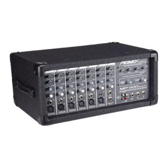
- Page 1 ™ M P 6 0 0 P o w e r e d M i x e r O p e r a t i n g G u i d e...
- Page 2 ATTENTION: Afin de réduire le risque de choc électrique, ne pas enlever le couvercle. Il ne se trouve à l’intérieur aucune pièce pouvant être reparée par l’utilisateur. Confiez I’entretien et la réparation de l’appareil à un réparateur Peavey agréé. AVERTISSEMENT: Afin de prévenir les risques de décharge électrique ou de feu, n’exposez pas cet appareil à la pluie ou à...
- Page 3 This owners manual explains the MP 600’s features and its proper operation. Each section of the mixer is separated into numbered illustrations. In each illustration you will be directed to a controls’...
-
Page 4: Rear Panel
REAR PANEL POWER This section describes the proper application of AC power to your MP 600. To ensure the safety of you and your MP 600, please pay close attention to any designated cautions. POWER SWITCH Used to turn AC mains power on or off. - Page 5 SPEAKER CONNECTIONS This section will help you locate the two speaker output jacks on the rear of your MP 600. Though there are two output jacks, they are mono (parallel) and not stereo. (2 — 8 ohms speakers) WARNING: NEVER ALLOW YOUR TOTAL SPEAKER IMPEDANCE TO DROP BELOW THE INDICATED MINIMUM IMPEDANCE.
- Page 6 Channel 7 Gain control turned up, or Feedback will occur. You may disconnect the tape inputs on the MP 600 if recording on the same tapedeck. Or, you may use a separate tape deck to play and record at the same time.
- Page 7 REVERB FOOTSWITCH Provided for connection of the optional remote footswitch. The footswitch is used to activate/defeat the reverb. You may use the ON/OFF single-button switch #0051000. EFFECTS OUTPUT Plugging into this mono (TS) 1/4" output disconnects the internal reverb, allowing you to utilize external effects devices.
-
Page 8: Specifications
NOTE: All specifications are typical unless otherwise noted. 0 dBV = 1 Volt RMS 0 dBu = .778 Volts RMS All specs are referenced to nominal output level (0 dBv) unless otherwise noted. All measurements are wideband 20 Hz to 20 kHz unless otherwise noted. -
Page 10: Hookup Diagram
™ HOOK UP DIAGRAM 112 TLS ™ Outputs on back Preamp out Effects Unit ® Tape Deck* 115s ™ *Tape deck and Effects Unit should not be connected at the same time. Both are shown for demonstration purposes only. - Page 11 ™ MEZCLADORA AMPLIFICADA Gracias por comprar la mezcladora Peavey MP 600. La MP 600 es una mezcladora de siete canales con una variedad de características incluidas, incluyendo un canal de entrada dedicada a niveles de línea (entrada sumada para un deck de cinta u otro aparato de nivel de línea), reverb digital de 32 bits, ecualizadores de canales y maestros, y un amplificador de 80 wats, todo dentro de una caja sólida.
- Page 12 REAR PANEL PODER Esta sección describe la aplicación correcta de poder CA a tu MP 600. Para asegurar tu seguridad y la de tu MP 600, por favor presta atención a todas las precauciones indicadas. SWITCH DE PODER Se usa para encender o interrumpir la corriente.
- Page 13 CUIDADO: Nunca permitas que el total de la impedancia de las bocinas caiga por debajo de la impedancia mínima. SALIDAS DE BOCINAS Dos conexiones paralelas de 1/4" son proporcionadas como salidas del amplificador. El mínimo de impedancia para las bocinas debe ser 4 ohmios. CARACTERÍSTICAS DE LOS CANALES (1-6) La siguiente sección describe los canales 1-6.
- Page 14 7 y con la ganancia subida, ya que resultará en retroalimentación. Puedes desconectar las entradas de cinta en la MP 600 si estás grabando al mismo deck. O, puedes usar un deck diferente para grabar y reproducir simultáneamente.
- Page 15 CONTROL DE PEDAL DE REVERB Se proporciona para la conexión de un controlador de pedal opcional. El pedal te permite activar o desactivar el reverb. Puedes usar el switch de un sólo botón #0051000. SALIDA DE EFECTOS El conectar a esta salida mono (TS) de 1/4" desconecta el reverb interno, permitiéndote utilizar procesadores de sonido externos.
- Page 16 Nivel máximo de entrada: Low Z = -11 dB Línea = +28 dB Poder Phantom: + 15 VDC Specifications subject to change without notice. MP 600 ESPECIFICACIONES MASTER: Ganancia: Main: = 10 dB (variable) EQ agudo: +/- 12 dB @ 10 kHz mínimo retén mínimo central +/- 2 dB...
- Page 17 32 bit, des équalisations par canal et master, et un étage de puissance de 80 W. Ce manuel explique toutes les fonctionnalités de la MP 600 et leur mode d’utilisation pour que vous puissiez en tirer au maximum.
- Page 18 Ce fusible est connecté à l’alimentation principale. Ne remplacez le fusible que par un mod- èle du même type et de même valeur. SI LE FUSIBLE GRILLE CONSTAMMENT, APPORTEZ L’APPAREIL À UN RÉPARATEUR PEAVEY AGRÉÉ. ATTENTION: NE REMPLACEZ CE FUSIBLE QUE LORSQUE LE CABLE D’ALIMENTATION EST DECONNECTE.
- Page 19 CANAUX 1 A 6 Certaines des caractéristiques et fonctionnalités des canaux 1 à 6 s’appliquent aussi au canal 7. ENTREE MICRO Cette entrée XLR est optimisée pour les micros et autres sources basses impédances. La borne 2 est l’entrée positive. L’alimentation Phantom (+15V) est appliquée aux bornes 2 et 3 en permanence (la borne 1 est à...
-
Page 20: Section Master
Master (16). INTERRUPTEUR REVERB AU PIED Permet la connexion d’une pédale de commande pour la réverbe. L’utilisation de l’interrupteur Peavey référence 0051000 est conseillée. SORTIE EFFETS En connectant un Jack à cette sortie, vous déconnecterez la réverbe interne et pourrez utilisez des effets externes. - Page 21 ATTENTION: Lors de l’utilisation d’un canal comme retour d’effets, il est important de régler son contrôle d’effets au minimum (position “0”). Si cette règle n’est pas appliquée, un larsen important surviendra pouvant endommager l’appareil ou vos haut-parleurs. SORTIE MAIN Sortie Jack asymétrique pouvant être utilisée pour la connexion à un ampli de puissance externe ou une autre table de mixage.
- Page 22 NOTE: All specifications are typical unless otherwise noted. 0 dBv = 1 Volt RMS 0 dBu = .778 Volts RMS All specs are referenced to nominal output level (0 dBv) unless otherwise noted. All measurements are wideband 20 Hz to 20 kHz unless otherwise noted.
- Page 23 Kassettendeck oder ein anderes Gerät), 32-bit digital Reverb, Kanal- und Master-Regler und einem 80 W-Verstärker, alles zusammen untergebracht in einer widerstandsfähigen Topbox. Diese Gebrauchsanleitung erklärt die Funktionen des MP 600 und seinen fachgerechten Betrieb. Jedes Teil des Mixers wird in durchnummerierten Abbildungen dargestellt. In jeder Abbildung werden Sie über entsprechende Referenznummern auf die Erklärung der Funktionen verwiesen.
- Page 24 REAR PANEL POWER (NETZANSCHLUSS) Dieser Abschnitt beschreibt den richtigen Stromanschluss an Ihren MP 600. Um Ihre Sicherheit und die Ihres MP 600 zu gewährleisten, beachten Sie bitte alle Warnhinweise genau. POWER SWITCH (NETZSCHALTER) Zum Ein-und Ausschalten der Stromzufuhr. FUSE (GERÄTESICHERUNG) Die Sicherung befindet sich im Deckel der Sicherungshalterung.
- Page 25 Achtung: Die Gesamt-Lautsprecher-Impedanz darf nie das angegebene Minimum unterschreiten. SPEAKER OUTPUTS (LAUTSPRECHERAUSGÄNGE) Am Verstärkerausgang sind zwei parallele 6,3 mm-Buchsen angebracht. Minimal-Impedanz für Lautsprecher ist 4 Ohm. KANAL (1 — 6) FUNKTIONEN Der folgende Abschnitt beschreibt die Kanäle 1 — 6. Diese Eingangskanäle sind alle gleich. Einige der unten angeführten Funktionen treffen auch auf Kanal 7 zu.
- Page 26 VORSICHT: Achten Sie darauf, nicht auf ein Gerät aufzunehmen, dessen Ausgang mit den Line/Tape-Eingangsbuchsen verbunden ist, und dass auf Kanal 7 nicht Gain aufgedreht ist, sonst kommt es zur Rückkoppelung. Sie können die Tape-Eingänge am MP 600 ausstecken, wenn Sie auf das gleiche Deck aufnehmen wollen. Oder verwenden Sie zum gleichzeitigen Aufnehmen und Abspielen unterschiedliche Kassettendecks.
- Page 27 REVERB FOOTSWITCH (REVERB FUSSSCHALTER) Für die Verbindung mit einem optionalen, entfernt aufgestellten Fußschalter. Der Fußschalter wird zum Ein-und Ausstellen des Halleffekts verwendet. Sie können ON/OFF Einknopf- Schalter #0051000 verwenden.. EFFEKTE OUTPUT (EFFEKTE-AUSGANG) Einstecken in diese Mono (TS) 6,3 mm Buchse trennt den internen Hall, so dass Sie externe Effekte verwenden können.
-
Page 28: Spezifikationen
Beachten Sie: Alle Spezifikationen sind die Regel, es sei denn, etwas anderes ist vermerkt. 0 dBv = 1 Volt RMS 0 dBu = 0,778 Volt RMS Alle Spezifikationen beziehen sich auf den nominalen Output (0 dBv), es sei denn, etwas anderes ist vermerkt. Alle Maße sind Breitband 20 Hz bis 20 kHz es sei denn, etwas anderes ist vermerkt. - Page 29 NOTES:...
-
Page 30: Important Safety Instructions
WARNING: When using electric products, basic cautions should always be followed, including the following: Read these instructions. Keep these instructions. Heed all warnings. Follow all instructions. Do not use this apparatus near water. For example, near or in a bathtub, swimming pool, sink, wet basement, etc. Clean only with a damp cloth. - Page 31 What Peavey Will Do We will repair or replace (at Peavey's discretion) products covered by warranty at no charge for labor or materials. If the product or component must be shipped to Peavey for warranty service, the consumer must pay initial shipping charges. If the repairs are covered by warranty, Peavey will pay the return shipping charges.
- Page 32 Features and specifications subject to change without notice. Peavey Electronics Corporation • 711 A Street • Meridian • MS • 39301 (601) 483-5365 • FAX (601) 486-1278 • www.peavey.com ©2000...