Table of Contents
Advertisement
Quick Links
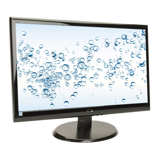
21.5" LCD Monitor
Service
Service
Service
Description
Table of Contents....................................................1
Revision List...................................................................2
Important Safety Notice.................................................3
1.Monitor Specification...................................................4
2.LCD Monitor Description.........................................5
3.Operation Instruction.................................................6
3.1.General Instructions..................................................6
3.2.Control Buttons and Connections...............................6
3.3.OSD Setting.............................................................8
4.Input/Output Specification........................................24
4.1.Input Signal Connector..........................................24
4.2.Preset Display Modes...... ..........................25
4.3.Panel Specification...........................................26
5.Block Diagram............................................................28
5.1.Main Board.....................................................28
5.2.Power Board..................................................29
ANY PERSON ATTEMPTING TO SERVICE THIS CHASSIS MUST FAMILIARIZE HIMSELF WITH THE CHASSIS
AND BE AWARE OF THE NECESSARY SAFETY PRECAUTIONS TO BE USED WHEN SERVICING ELECTRONIC
CAUTION: USE A SEPARATE ISOLATION TRANSFOMER FOR THIS UNIT WHEN SERVICING
R FOR TH
Table of Contents
Page Description
SAFETY NOTICE
EQUIPMENT CONTAINING HIGH VOLTAGES.
6.Schematic..........................................................30
6.1.Main Board.......................................................30
6.2.Power Board....................................................34
6.3.Key Board....................................................36
7.PCB Layout.........................................................37
7.1.Main Board......................................................37
7.2.Power Board.....................................................39
7.3.Key Board........................................................42
8.Maintainability.....................................................43
8.1.Equipments and Tools Requirement..................43
8.2.Trouble Shooting.............................................44
9.White-Balance,Luminance Adjustment.................48
10.Monitor Exploded View......................................50
11.BOM List......................................................51
AOC e2250Swnk
Horizontal Frequency
30 - 83kHz
Page
Advertisement
Table of Contents

Related Manuals for AOC e2250Swnk


Summary of Contents for AOC e2250Swnk
-
Page 1: Table Of Contents
21.5" LCD Monitor AOC e2250Swnk Service Service Service Horizontal Frequency 30 - 83kHz Table of Contents Description Page Description Page Table of Contents…………………..…………………..…...1 6.Schematic…………..….........30 Revision List.…...........……..2 6.1.Main Board..…….…...........30 Important Safety Notice.….…......……..3 6.2.Power Board..……….........34 1.Monitor Specification......………....4 6.3.Key Board..……….........36 2.LCD Monitor Description……….……………………..5 7.PCB Layout..………..........37... -
Page 2: Revision List
Revision List Version Release Date Revision History TPV Model Name TIB2RV2BAGA3NNE TIA4RV2BAGA2NNE Initial release Oct.-31-2012 TIA4RV2BAGA3NNE TIA4RV2BAGACNNE... -
Page 3: Important Safety Notice
Important Safety Notice Proper service and repair is important to the safe, reliable operation of all AOC Company Equipment. The service procedures recommended by AOC and described in this service manual are effective methods of performing service operations. Some of these service operations require the use of tools specially designed for the purpose. The special tools should be used when and as recommended. -
Page 4: Monitor Specification
1.Monitor Specifications... -
Page 5: Lcd Monitor Description
2.LCD Monitor Description The LCD monitor will contain a main board, a Power board and a key board which house the flat panel control logic, brightness control logic and DDC. The power part will provide AC to DC Inverter voltage to drive the backlight of panel and the main board chips each voltage. -
Page 6: Operation Instruction
3. Operating Instructions 3.1 General Instructions Press the power button to turn the monitor on or off. The other control knobs are located at front panel of the monitor (See Figure ). By changing these settings, the picture can be adjusted to your personal preferences. * The power cord should be connected. - Page 7 1. Power 2. Analog (DB-15 VGA cable) To protect equipment, always turn off the PC and LCD monitor before connecting. 1 Connect the power cable to the AC port on the back of the monitor. 2 Connect one end of the 15-pin D-Sub cable to the back of the monitor and connect the other end to the computer's D-Sub port.
-
Page 8: Osd Setting
3.3 OSD Setting Basic and simple instruction on the control keys. 1)Press the MENU-button to activate the OSD window. 2) Press - or + to navigate through the functions. Once the desired function is highlighted, press the MENU-button to activate it . press - or + to navigate through the sub-menu functions. Once the desired function is highlighted, press MENU-button to activate it. - Page 9 Luminance Press (Menu) to display menu. Press to select (Luminance), and press to enter. Press to select submenu, and press to enter. Press to adjust.
- Page 10 Press two times to exit.
- Page 11 Image Setup Press (Menu) to display menu. Press to select (Image Setup), and press to enter. Press to select submenu, and press to enter. Press to adjust.
- Page 12 Press two times to exit.
- Page 13 Color Setup Press (Menu) to display menu. Press to select (Color Setup), and press to enter. Press to select submenu, and press to enter. Press to adjust.
- Page 14 Press two times to exit.
- Page 15 Picture Boost Press (Menu) to display menu. Press to select (Picture Boost), and press to enter. Press to select submenu, and press to enter. Press to adjust.
- Page 16 Press two times to exit.
- Page 17 OSD Setup Press (Menu) to display menu. Press to select (OSD Setup), and press to enter. Press to select submenu, and press to enter. Press to adjust.
- Page 18 Press two times to exit.
- Page 19 Extra Press (Menu) to display menu. Press to select (Extra), and press to enter. Press to select submenu, and press to enter.
- Page 20 Press to adjust. Press two times to exit.
- Page 21 Exit Press (Menu) to display menu. Press to select (Exit), and press to enter. Press two times to exit...
- Page 22 Orange or red e-Saver Welcome to use AOC e-Saver monitor power management software! The AOC e-Saver features Smart Shutdown functions for your monitors, allows your monitor to timely shutdown when PC unit is at any status (On, Off, Sleep or Screen Saver);...
- Page 23 Screen+ Welcome to "Screen+" software by AOC, Screen+ software is a desktop screen splitting tool, it splits the desktop into different panes, each pane displays a different window. You only need to drag the window to a corresponding pane, when you want to access it. It supports multiple monitor display to make your task easier. Please follow the installation...
-
Page 24: Input/Output Specification
4. Input/Output Specification 4.1 Input Signal Connector... -
Page 25: Preset Display Modes
.2 Preset Display Modes... -
Page 26: Panel Specification
4.3 Panel Specification 4.3.1 General Features TPM215HW01-HGEL03 is a 21.5” TFT Liquid Crystal Display module with WLED Backlight unit and 30 pins 2ch-LVDS interface. This module supports 1920 x 1080 Full HD mode and can display up to 16.7M colors.The converter module for Backlight is not built in. - Page 27 LED array electrical characteristics Ta = 25 ±2℃ 4.3.4 Optical Characteristics 25°C...
-
Page 28: Block Diagram
04.Output 05.Power 03.Scalar T P V ( Top Victory Electronics Co . , Ltd. ) OEM MODEL Size AOC 50 ID(1A) 絬 隔 瓜 絪 腹 715G4737-M0B-000-0040_101028 TPV MODEL AOC 50 ID(1A) Key Component 01.Top PCB NAME 715G4737-M0B <称爹> 称 爹... -
Page 29: Power Board
5.2 Power Board Transformer Rectifier Bridge 14.5V EMI filter (T901) diodes Rectifier and Filter Start Resistor (R908,R911) Feedback PWM Control Circuit Power Switch LD7576AGR (U901) (Q901) Photo coupler Regulator (U902) (IC903) L801 D801 14.5V C809 MOSFET (Q801) (CN804) PWM Control ON/OFF OZ9998BGN (U801) -
Page 30: Schematic
DDC1_SCL Q407 LMBT3904LT1G EDID_CTRL T P V ( Top Victory Electronics Co . , Ltd. ) OEM MODEL AOC 50 ID(1A) Size 絬 隔 瓜 絪 腹 715G4737-M02-000-0040_110620 TPV MODEL AOC 50 ID(1A) Key Component 02.Input PCB NAME 715G4737-M02 称 爹... - Page 31 NC/CONN C433 NC/CONN ZD401 T P V ( Top Victory Electronics Co . , Ltd. ) OEM MODEL AOC 50 ID(1A) Size NC/RLZ5.6B 絬 隔 瓜 絪 腹 TPV MODEL 715G4737-M02-000-0040_110620 AOC 50 ID(1A) Key Component 03.Scalar PCB NAME 715G4737-M02 <称爹>...
- Page 32 120OHM C421 100UF 16V T P V ( Top Victory Electronics Co . , Ltd. ) OEM MODEL Size AOC 50 ID(1A) AO3401A 絬 隔 瓜 絪 腹 715G4737-M02-000-0040_110620 TPV MODEL AOC 50 ID(1A) Key Component 04.Output PCB NAME 715G4737-M02 称...
- Page 33 R486 0 ohm T P V ( Top Victory Electronics Co . , Ltd. ) OEM MODEL Size AOC 50 ID(1A) 絬 隔 瓜 絪 腹 715G4737-M02-000-0040_110620 TPV MODEL AOC 50 ID(1A) Key Component 05.Power PCB NAME 715G4737-M02 称 爹...
-
Page 34: Power Board
6.2 Power Board 715G4744P01003001M R929 100 OHM 1/4W BD901 C916 C928 F801 KBP208G R930 100 OHM 1/4W 2N2 500V 2N2 500V 0R05 1/4W +14.5V R903 100 OHM 1/4W R904 ZD901 250OHM2W MTZJ T-72 16B 80GL22T-3 C918 680UF/25V T901 D901 POWER X'FMR SR515 R905 470OHM +-5% 1/8W... - Page 35 FB802 D801 L801 CN803 +14.5V C801 47UH BEAD Q801 330uF 25V R804 C814 SK310B 100N 50V 10 OHM 1/8W APM8005KCTRG R801 C810 R815 10K 1/8W 0.47UF 50V R819 R820 R821 R822 160K 1/8W NC/CONN ON/OFF R814 R802 10 OHM 1% 1/4W C809 R805 300K 1/8W...
-
Page 36: Key Board
6.3 Key Board 715G4747K02000001C LED001 CN001 LBADC1 R001 2KOHM 1% 1/10W LBADC2 DC_POWERON R002 0R01 1/10W LED_1# LED_2# C001 C002 R003 2KOHM 1% 1/10W R004 1K 1/10W NC/0.1uF 50V NC/0.1uF 50V Wire Harness SGND SW005 SW004 SW003 SW002 SW001 AUTO(2.0K) 1.118V LBADC1 DOWN... -
Page 37: Pcb Layout
7. PCB Layout 7.1 Main Board 715G4737M02000004I... -
Page 39: Power Board
7.2 Power Board 715G4744P01003001M... -
Page 42: Key Board
7.3 Key Board 715G4747K02000001C... -
Page 43: Maintainability
8. Maintainability 8.1 Equipments and Tools Requirement Voltmeter. Oscilloscope. Pattern Generator. DDC Tool with an IBM Compatible Computer. Alignment Tool. LCD Color Analyzer. Service Manual. User Manual. -
Page 44: Trouble Shooting
8.2 Trouble Shooting 1. No Power No power Check power cable is Re-plug the power cable tightened? Check Power “On/Off” Turn on the Power “On/Off” switch is “On”? Check the LED Check the AC power indicate is OK? Replace the converter board Replace main board and check connections Replace key board and check connections... - Page 45 2. No Video (Power LED Blue) No Video (Power LED Blue) Press the power Replace the main board button is OK? Replace the converter The end board Replace the main The end board and connection Replace the LVDS/FFC Check the LVDS/FFC cable or panel cable or panel Replace the key board...
- Page 46 3. DIM DIM (image overlap, focus or flicker) The end Reset in factory mode Set to the optimal The end frequency, select the recommended frequency Readjust the phase and pixel The end clock in the user mode Pull out signal cable and Check the signal cable check “Self Test Feature and the PC...
- Page 47 4. Color is not optimal Color is not optimal Color shift Miss color Reset the factory mode Replace the signal cable In the user mode, set the” color settings” until customer satisfy The end Pull out the signal cable and check the screen color display is normal? Replace the signal cable or PC Replace the main board...
-
Page 48: White-Balance,Luminance Adjustment
9.White- Balance, Luminance Adjustment Approximately 30 minutes should be allowed for warm up before proceeding white balance adjustment. How to setting MEM channel you can reference to chroma 7120 user guide or simple use “SC” key and “NEXT” Key to modify xyY value and use “ID” key to modify the TEXT description Following is the procedure to do white-balance adjust . - Page 49 C. Adjust Cool (9300K) color-temperature 1. Switch the Chroma-7120 to RGB-Mode (with press “MODE” button) 2. Switch the MEM. Channel to Channel 9 (with up or down arrow on chroma 7120) 3. The LCD-indicator on chroma 7120 will show x=283±20,y=297±20 4.
-
Page 50: Monitor Exploded View
10. Monitor Exploded Views PART NAME Q'TY BEZEL FUNCTION BUTTON POWER LENS MYLAR MAIN FRAME HINGE PLATE REAR COVER HINGE STAND STAND COVER BASE RUBBER FOOT HINGE COVER... -
Page 51: Bom List
KEPCAHB5 KEY BOARD PLPCBB481AHD1 POWER BOARD Q45G 77 5 PE PACKING Q50G 4 10 TIE (Y1900221) Q52G 1185 99 BIG CARTON TAPE FOR AOC 72MM M05201 Q52G100202500A00JY AL FOIL M05202 Q52G100204500A00JY AL FOIL M05203 Q52G100204500A00JY AL FOIL Q52G1801MNT160CFLT INSULATING SHEET... - Page 52 756GHBCB A1114 MAIN BOARD-CBPCBRVA1H1 SMTCB-U402 100GARMI003W11 MCU ASS'Y-056G2233 11 CN408 033G3802 6B Y WAFER CN404 033G3802 9B Y CONN 2.0 9P CN403 033G801930F CH JS FFC CONN 1.0mm 30P R/A 34mm 6.3mm CN101 088G 35315FVCL D-SUB CONN V/T 15P BLUE H=10.4 X401 093G 22 53CEC CRYSTAL S-F-14.31818M-32-3030-2085-30...
- Page 53 Q55G 100625 TIN STICK_LOW ARGENTUM U901 056G 379529 AC/DC CONVERTER IC LD7576AGR SOP-7 U801 056G 700 11 LED DRIVER OZ9998BGN-A1-0-TR SOP-16 Q801 057G 763 92 FET P8008HV 4A/80V SOP-8 RJ801 061G0805000 JF RST CHIPR 0 OHM +-5% 1/8W FENGHUA R811 061G0805000 JF RST CHIPR 0 OHM +-5% 1/8W FENGHUA R804...
- Page 54 C914 065G080510232K CAP CHIP 0805 1N 50V X7R +/-10% C906 065G080510232K CAP CHIP 0805 1N 50V X7R +/-10% C815 065G080510232K CAP CHIP 0805 1N 50V X7R +/-10% C802 065G080510332K CAP CHIP 0805 10N 50V X7R +/-10% C915 065G080510332K CAP CHIP 0805 10N 50V X7R +/-10% C814 065G080510432K CAP CHIP 0805 0.1UF K 50V X7R...
- Page 55 C911 065G 2K152 2T6921 CAP CER 1500pF K 2KV Y5P C805 065G250K1052HT CAP CER 1UF 10% 25V X7R C903 065G305M1023WR CAP Y2 1NF 20% 250V Y5U C902 065G305M1023WR CAP Y2 1NF 20% 250V Y5U C900 065G306M22233R CAP Y1 2.2NF 20% 250V Y5U C927 065G500K4732HT CAP CER 47NF 10% 50V X7R...
- Page 56 R481 061G0402000 JT RST CHIPR MAX0R05 1/16W TZAI YUAN R402 061G0402000 JT RST CHIPR MAX0R05 1/16W TZAI YUAN R401 061G0402000 JT RST CHIPR MAX0R05 1/16W TZAI YUAN R420 061G0402101 JT RST CHIP 100R 1/16W 5% TZAI YUAN R413 061G0402101 JT RST CHIP 100R 1/16W 5% TZAI YUAN R412 061G0402101 JT...
- Page 57 R101 061G0603000 JT RST CHIP MAX 0R05 1/10W TZAI YUAN R468 061G0603331 JT RST 0603 330R 5% 1/10W R471 061G0603471 JT RST CHIPR 470OHM +-5% 1/10W TZAI YUAN R479 061G1206000 JF RST CHIPR MAX0R05 1/4W FENGHUA R434 061G1206301 JT RST CHIPR 300 OHM +-5% 1/4W TZAI YUAN R477 061G1206301 JT RST CHIPR 300 OHM +-5% 1/4W TZAI YUAN...