Table of Contents
Advertisement
Volume 1
Hardware and Installation
Preface, Contents
User Information
Installation
AS-i
I/Os
Appendix
General Technical Specifica-
tions
Guidelines for Handling ESD
Devices
Safety of Electronic Controllers
SIMATIC C7 and S7 Refer-
ences
Glossary, Index
1
2
3
4
5
6
7
8
A
B
C
D
Advertisement
Chapters
Table of Contents

Related Manuals for Siemens simatic c7-621


Summary of Contents for Siemens simatic c7-621
-
Page 1: Table Of Contents
Preface, Contents User Information Product Overview SIMATIC Installation Installing and Preparing the C7 C7-621 / C7-621 AS-i Control Systems Configuring an MPI Network Connecting a Programming Volume 1 Device / PC to a C7 Hardware and Installation AS-i Manual Attaching a C7-621 AS-i I/Os C7-621 Digital I/Os C7-621 Analog I/Os... -
Page 2: Simatic
Trademarks SIMATIC and SMATIC NET are registered trademarks of SIEMENS AG. Third parties using for their own purposes any other names in this document which refer to trademarks might infringe upon the rights of the trademark owners. Copyright... -
Page 3: C7-621 / C7-621 As-I Control Systems
Preface Purpose This manual will help you with the following tasks: Installing and wiring up a C7-621 or C7-621 AS-i (Volume 1) Assigning parameters to the CPU of the C7-621 or C7-621 AS-i, downloading a user program to the CPU, and starting up (Volume 2) Making the settings required on the C7-621 and C7-621 AS-i for operation and using the operator interface functions... - Page 4 Preface Volume 2 of the manual deals with the following topics: Startup of the C7 Controlling with the C7 CPU Addressing and assigning parameters for the C7 I/Os C7 diagnostics AS-i system concept Using and operating AS-i Using the operator interface functions of the C7 Conventions for To make the manual easier to read, the device types C7-621 or C7-621 AS-i will simply by called C7 in the manual.
- Page 5 To familiarize yourself with the AS-i system, we recommend the following Brochure procedure: You should certainly read the AS-i brochure. Actuator Sensor Interface Order number E20001-P285-A497-V2-X-7600 This brochure can be ordered from all Siemens offices. C7-621 / C7-621 AS-i Control Systems C79000-G7076-C621-01...
- Page 6 Preface Table 1-1 STEP 7 Documentation Package, Order Number 6ES7810-4AA00-8AA0 Manual Topics Standard Software for S7 and This provides information about working with the STEP 7 tools. Installation and startup of STEP 7 on a PC/programming device STEP 7 User Manual Using the tools: –...
- Page 7 Preface Further Appendix D of Volume 2 of this manual contains a list with further sources of Information information about the S7-300 and programmable logic controllers. Table 1-2 Further Manuals Manual Topics Programming Manual: This manual contains basic information about designing STEP 7 programs: System Software for S7-300 and Introduction to the efficient solution of programming tasks using a S7-400, Program Design...
- Page 8 If you have questions about the C7 control system, please contact your Siemens representative. There is a list with the addresses of Siemens representatives world-wide in Appendix E of Volume 2 of the manual. If you have questions or comments about the manual itself, please complete and return the remarks form.
-
Page 9: C79000-G7076-C621-01
Contents Product Overview ............Installing and Preparing the C7 . -
Page 10: C7-621 Digital I/Os
Contents C7-621 Digital I/Os ............Digital Inputs . -
Page 11: Product Overview
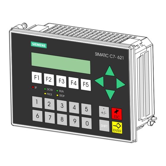
Product Overview In This Chapter This chapter introduces you to the C7-621 and C7-621 AS-i. A brief overview of the range of performance will give you a first impression of the two devices. This chapter also explains the additional components that you can connect to a C7. - Page 12 Product Overview Overview There are two versions of the C7: C7-621 With a two-line display and 20 characters per line with 5 mm high characters (see Figure 1-1). The C7-621 has the following components: MPI interface Digital inputs and outputs Analog inputs and outputs P bus connection (for the IM 621 module) Figure 1-1...
- Page 13 Product Overview C7-621 Units The C7 has two independent units that communicate with each other via an internal MPI interface: C7 CPU with digital and analog inputs and outputs C7 OP Where necessary, these units are dealt with separately in the manuals. C7-621 AS-i With a two-line display and 20 characters per line with characters 5 mm high (see Figure 1-2).
- Page 14 Product Overview C7-621 AS-i Units The C7 has two independent units that communicate with each other via an internal MPI interface. C7 CPU with C7 AS-i CP C7 OP When necessary, these units are dealt with separately in the manuals. C7-621 / C7-621 AS-i Control Systems C79000-G7076-C621-01...
- Page 15 Product Overview Components that Apart from the connections to the process you can also connect various Can Be Connected components to the C7. The most important components and their functions to a C7 are listed in Table 1-1: Table 1-1 Components that Can Be Connected to a C7 Component Function...
- Page 16 Product Overview Table 1-1 Components that Can Be Connected to a C7, continued Component Function Schematic Programming device (PG) or PC ...configures, assigns with the STEP 7 software parameters, programs, and tests package and ProTool or Pro the C7. Tool/Lite RS 485 repeater ...amplifies the signals in an MPI or PROFIBUS DP network...
- Page 17 Product Overview Overview of the C7 The SIMATIC C7-621/C7-621 AS-i devices consist of several components that interact with each other: A programmable controller CPU of the SIMATIC S7-300 class (C7 CPU), A line-oriented SIMATIC OP (C7 OP), Integrated digital and analog I/Os (C7-621 I/Os),...
- Page 18 Product Overview The basic functions also correspond to those of a modular configuration with standard modules from the programmable controller and OP families, the individual components operate independently of each other and each of the processors has its own memory. C7 CPU is programmed with STEP 7 and the C7 OP is configured with ProTool/Lite.
-
Page 19: Installing And Preparing The C7
Installing and Preparing the C7 Chapter Section Description Page Overview Components and Accessories of the C7 Installing a C7 Location of the C7 Electrical Installation and Pinouts Guidelines for Trouble-Free Installation 2-13 Connecting Up Cables 2-15 Connector Key Inserts 2-16 Contrast 2-17 I/O Expansion with the IM 621... -
Page 20: Components And Accessories Of The C7
Installing and Preparing the C7 Components and Accessories of the C7 Components The following components are supplied with the C7-621: Supplied with the C7-621 (order number 6ES7 621-1AD00-0AE3) C7-621 Grounding bar 6 shield clips Seal and 4 securing posts Set of connectors for C7 I/Os with key inserts Product information Components of the The following components are supplied with the C7-621 AS-i:... -
Page 21: Installing A C7
Installing and Preparing the C7 Installing a C7 The Installation The C7 is designed for fixed installation in a switching panel or wiring closet door. To install the C7, follow the steps outlined below: Step Action Cut out a section of the switching panel as shown in Figure 2-2. Insert the sealing ring behind the front panel (see Figure 2-1). - Page 22 Installing and Preparing the C7 159+0,5 Cutout in front panel +0,5 Figure 2-2 Dimension Drawings for the C7 Securing Post Before Engaging Figure 2-3 Securing Post Before Engaging Securing Post Engaged Figure 2-4 Securing Post Engaged, with Screw C7-621 / C7-621 AS-i Control Systems C79000-G7076-C621-01...
- Page 23 Installing and Preparing the C7 Releasing the To release a securing post, follow the steps outlined below: Securing Post Step Action Loosen the screw. Lever the securing post upwards ( in Figure 2-5). Lever the securing post out of the guide ( in Figure 2-5).
-
Page 24: Location Of The C7
Installing and Preparing the C7 Location of the C7 Points to Note When installing the C7, please remember the following points: When Installing The thickness of the switching panel can be between 1 and 4 mm. Make the C7 sure that the sealing ring makes a tight seal all round. There must be a clearance of at least 50 mm above and below and 70 mm at the sides of the C7 as shown in Figure 2-6. -
Page 25: Electrical Installation And Pinouts
Installing and Preparing the C7 Electrical Installation and Pinouts Overview To allow various components to be connected, the C7 is equipped with male and female connectors. C7-621 and C7-621 Figure 2-7 illustrates the connection of the C7 power supply for a C7-621. AS-i The pinouts of the connectors are shown in the following tables. - Page 26 Installing and Preparing the C7 C7-621 Figure 2-8 illustrates the C7-621 with digital and analog connectors. These connectors only exist on the C7-621. The pinouts of the connectors are shown in the following tables. Digital input (top) left right bottom Digital output (bottom) Analog input Analog output...
- Page 27 Installing and Preparing the C7 Table 2-2 Pinout of the Digital Inputs, continued Signal Function I125.6 Digital input 14 I125.7 Digital input 15 Digital Ouput Table 2-3 Pinout of the Digital Outputs Signal Function Q124.0 Digital output 0 Q124.1 Digital output 1 Q124.2 Digital output 2 Q124.3...
- Page 28 Installing and Preparing the C7 Analog Input/ Output Table 2-4 Pinout of the Analog Inputs/Outputs Function AI1-U Analog input 1, signal input for voltage AI1-I Analog input 1, signal input for current AI1-M Analog input 1, reference potential AI2-U Analog input 2, signal input for voltage AI2-I Analog input 2, signal input for current AI2-M...
- Page 29 Installing and Preparing the C7 C7-621 AS-i The figure illustrates the AS-i connector of the C7-621 AS-i. This connector only exists on the C7-621 AS-i. AS-i connector Figure 2-10 C7-621 AS-i with AS-i Connector AS-i Connector To connect actuators, sensors and the AS-i power supply unit Table 2-5 Pinout of the AS-Interface Function...
- Page 30 Installing and Preparing the C7 Device Connectors You can use the following connecting cables to connect the C7 to other of the C7 components: Table 2-6 Connecting Cables for the C7 Connectors Connecting Cable Comments Schematic Connection Between ... MPI Interface PG cable S7-300 S7-400...
-
Page 31: Guidelines For Trouble-Free Installation
Installing and Preparing the C7 Guidelines for Trouble-Free Installation Overview To prevent disturbances, the wiring and cabling in an automation system must be installed according to certain rules. If a system is poorly grounded or not shielded, low frequency and high frequency interference signals can be coupled into the internal bus of the controller and cause malfunctions. - Page 32 Installing and Preparing the C7 All the doors and metal panels (side, rear and top panels) of the wiring closet should be connected at least three times to the closet frame (keep the connections short and make sure that contact is over a large area with bare, unpainted metal).
-
Page 33: Connecting Up Cables
Installing and Preparing the C7 Connecting Up Cables Overview This chapter describes how to connect the shield of shielded signal cables with ground. The shield is connected directly to the ground terminal of the C7 via a grounding bar. Procedure Fit the grounding bar and the shield clips supplied with the C7-621 as follows: 1. -
Page 34: Connector Key Inserts
Installing and Preparing the C7 Connector Key Inserts Overview You can order a set of connectors with key inserts for a C7 (see Section 2.1, Accessories). How you key or code the connectors is explained below: Keying With the solid keys and the profile keys (see Figure 2-12) you can Connectors... -
Page 35: Contrast
Installing and Preparing the C7 Contrast Setting the You can set the contrast of the C7 display using the screw as shown in Figure Contrast 2-13 and adapt the contrast to the lighting conditions. Figure 2-13 Setting the Contrast C7-621 / C7-621 AS-i Control Systems 2-17 C79000-G7076-C621-01... -
Page 36: I/O Expansion With The Im
Installing and Preparing the C7 I/O Expansion with the IM 621 Additional S7-300 You can connect further S7-300 I/Os to the C7 via the P bus connector of the Modules C7-621 or C7-621 AS-i. How you install the S7 modules, is described in the manual /71/. Note You can connect a maximum of four I/O modules to the C7. - Page 37 Installing and Preparing the C7 Modules Slot number IM 621 124.0...125.7 Digital address Analog address 128...135 Figure 2-14 Maximum Configuration with a C7-621 Modules Slot number IM 621 Figure 2-15 Maximum Configuration for a C7-621 AS-i C7-621 / C7-621 AS-i Control Systems 2-19 C79000-G7076-C621-01...
-
Page 38: Memory Reset On The C7
Installing and Preparing the C7 2.10 Memory Reset on the C7 Memory Reset on The C7 must be turned off. To reset the memory of the C7 OP, follow the the C7 OP steps outlined below: 1. Press and hold down the following keys at the same time: 2. - Page 39 Installing and Preparing the C7 Memory Reset on The section below describes how to reset the C7 CPU memory with the the C7 CPU Using C7 CPU Mode system function: the System Function 1. Select the system functions menu by pressing the keys The following is displayed on the C7-621: C7 System Functions IN/OUT...
- Page 40 Installing and Preparing the C7 The following menu is displayed. MODE:STOP = Anwahl der DIR–Funktion RUNP RUN STOP MRES DC5V LED displays FRCE STOP Figure 2-18 “C7 CPU Modes” Menu with Function Keys 4. Select the STOP function by pressing The STOP LED lights up.
-
Page 41: Status And Error Leds On The C7
Installing and Preparing the C7 2.11 Status and Error LEDs on the C7 Status and Error The C7-621 or C7-621 AS-i has the following status and error LEDs: LEDs DC5V FRCE STOP Figure 2-19 Status and Error LEDs of the C7-621 or C7-621 AS-i Meaning of the The status and error LEDs are explained in the order in which they appear on Status and Error... -
Page 42: Clocks On The C7
Installing and Preparing the C7 2.12 Clocks on the C7 Overview The C7 devices have two software clocks: One clock on the C7 CPU One clock in the C7 OP Clock on the The clock of the C7 CPU is a software clock. This clock is independent of C7 CPU the clock of the C7 OP. - Page 43 Installing and Preparing the C7 Run-Time Meter The C7 CPU is equipped with a run-time meter. This allows you to count the operating hours of the C7 CPU or a resource it controls. You program the run-time meter in the user program using the SFCs 2 “SET_RTM”, 3 “CTRL_RTM”...
- Page 44 Installing and Preparing the C7 C7-621 / C7-621 AS-i Control Systems 2-26 C79000-G7076-C621-01...
-
Page 45: Configuring An Mpi Network
Configuring an MPI Network In this Chapter This chapter describes how to configure an MPI network. You will learn the following: Which communication options are available to you with an MPI network. The components to which you can connect the nodes of an MPI network. The maximum and minimum cable lengths you can use. -
Page 46: Communication Via The Mpi Interface
Configuring an MPI Network Communication via the MPI Interface Definition: The C7 interface for connecting devices such as programming devices is Multipoint known as the Multipoint Interface since several devices at different locations Interface MPI (points) can communicate with the C7 via this interface. Transmission Rate The transmission rate of the C7 is fixed at 187.5 Kbps. - Page 47 Configuring an MPI Network Default MPI The following table shows the default MPI addresses set on the devices when Addresses of the they are shipped. Node (Device) Default Default Highest MPI MPI Address Address C7 OP Depends on the OP C7 CPU Rules for MPI When assigning MPI addresses, keep to the following rules:...
-
Page 48: Rules For Configuring An Mpi Network
Configuring an MPI Network Rules for Configuring an MPI Network Overview This section deals with the following topics: How to configure an MPI network Rules for configuring the network Rules Remember the following rules when connecting nodes to an MPI network: Before interconnecting the individual nodes of the MPI network, you must first assign the MPI address and the highest MPI address to each node (except for the RS 485 repeater). - Page 49 Configuring an MPI Network Recommendation Avoid assigning the default MPI addresses (see below) as fixed node for MPI Addresses addresses in the network otherwise address conflicts can occur when you on the Network replace devices or expand the network (MPI addresses assigned twice). Reserve MPI address “0”...
- Page 50 L+ M PE M 5.2 24 V Terminating resistor bus segment 1 Terminating resistor SIEMENS bus segment 2 Figure 3-2 Terminating Resistor on the RS 485 Repeater Example of Figure 3-3 shows a possible MPI configuration in which the terminating Termination in an resistor must be activated.
- Page 51 Configuring an MPI Network Example of an MPI Figure 3-4 shows the basic configuration of an MPI subnet using the rules Subnet listed above. S7-300 S7-300 S7-300 OP 25** PROFI- subnet*** À 3 + 4 S7-300 S7-300 S7-300 OP 25 OP 25 À...
-
Page 52: Cable Lengths
Configuring an MPI Network Cable Lengths Segment in an MPI The maximum cable length in one segment of an MPI network is 50 m. Network These 50 m represent the distance from the first node to the last node on the segment. - Page 53 Configuring an MPI Network Example Figure 3-6 shows a possible MPI network configuration. The example illustrates the distances that can be achieved in an MPI network. À S7-300 S7-300 OP 25 RS 485 repeater À À max. Connecting cable 1000 m max.
-
Page 54: Network Components
Configuring an MPI Network Network Components Purpose You require network components in the following situations: Table 3-2 Network Components Purpose Component ... to install the network PROFIBUS LAN cable ... to connect a node to the network Bus connector ... to amplify the signal RS 485 repeater ... - Page 55 Configuring an MPI Network Cabling Rules When laying the PROFIBUS LAN cable, make sure you keep to the following rules: Do not twist the cable Do not stretch the cable Do not crimp the cable When laying the interior LAN cable, the following restrictions must also be taken into account (d = outer diameter of the cable): Table 3-5...
-
Page 56: Bus Connectors
Configuring an MPI Network Bus Connectors Purpose of the The bus connector is used to connect the PROFIBUS LAN cable to the MPI Bus Connector interface. This establishes the connection to further nodes. There are five different bus connectors: Up to 12 Mbps PROFIBUS bus connector (6GK1500-0EA00) Up to 12 Mbps –... -
Page 57: Profibus Bus Connector
Configuring an MPI Network 3.5.1 PROFIBUS Bus Connector Appearance Figure 3-7 shows the PROFIBUS bus connector with order number (6GK15000-0EA00.) 6GK1500-0EA00 Figure II: Bus connector for the first and last node on the PROFIBUS network. The cable can be connected either from the left or right. Switch setting for the first and last station on the PROFIBUS network: “ON”... -
Page 58: Bus Connector 6Es7 972-0B.20-0Xa0
Configuring an MPI Network Fitting the Fit the PROFIBUS bus connector with order number 6GK1500-0EA00 to the Connector to the LAN cable as follows: LAN Cable 1. Strip the cable. 2. Insert the green and red wires into the screw terminals. 3. - Page 59 Configuring an MPI Network Fitting the Bus Fit the bus connector with order number 6ES7 972-0B.20 ... to the LAN Connector to the cable as follows: LAN Cable 1. Strip the insulation from the LAN cable as shown in Figure 3-10. Vertical Cable Outlet Without PG interface With PG interface...
- Page 60 Configuring an MPI Network 5. Fit the green and red wires into the screw terminal as shown in Figure 3-11. Make sure that you always insert the same colored wire into the same terminal on all connectors (for example the green wire into terminal A and the red wire into terminal B, or vice-versa).
-
Page 61: Bus Connector 6Es7 972-0B.10-0Xa0
Configuring an MPI Network 3.5.3 Bus Connector 6ES7 972-0B.10-0XA0 Appearance Table 3-6 shows the bus connector 6ES7 972-0B.10-0XA0 Table 3-6 Description and Functions of the Bus Connector 6ES7 972-0B.10-0XA0 Front View of the Bus Connector Function Connection to With PG Interface Without PG Interface the MPI, PROFIBUS DP... - Page 62 Configuring an MPI Network 5. Fit the green and red wires into the screw terminal block as shown in Figure 3-13. Make sure that you always fit the same wires to the same terminal A or B (for example always connect the green wire to terminal A and the red wire to terminal B or vice-versa).
-
Page 63: Connecting The Bus Connector To A Module
Configuring an MPI Network 3.5.4 Connecting the Bus Connector to a Module Connecting the To connect the bus connector, follow the steps outlined below: Bus Connector 1. Plug the bus connector into the module. 2. Screw the bus connector securely to the module. 3. - Page 64 Configuring an MPI Network C7-621 / C7-621 AS-i Control Systems 3-20 C79000-G7076-C621-01...
-
Page 65: Connecting A Programming Device / Pc To A C7
Connecting a Programming Device / PC to a C7 Chapter Section Description Page Overview Connecting a Programming Device/PC to a C7 Connecting a Programming Device/PC to Several Nodes C7-621 / C7-621 AS-i Control Systems C79000-G7076-C621-01... -
Page 66: Connecting A Programming Device / Pc To A C7
Connecting a Programming Device / PC to a C7 Connecting a Programming Device / PC to a C7 Possibilities This chapter explains the ways in which you can connect a programming device or PC to the C7 via the multipoint interface. Cable Lengths For information about the possible cable lengths, refer to Section 3.3. -
Page 67: Connecting A Programming Device/Pc To Several Nodes
Connecting a Programming Device / PC to a C7 Connecting a Programming Device/PC to Several Nodes Possibilities This section explains how to connect a programming device or PC to more than one node networked via the multipoint interface. Two Installation When you connect a programming device/PC to more than one node, you Options must distinguish between two different types of connection:... - Page 68 Connecting a Programming Device / PC to a C7 Permanently You connect the permanently installed PG/PC in the MPI network to one or Installed more nodes of the MPI network according to the rules explained in Section Programming 3.2. Device/PC Figure 4-2 shows a C7 network with two C7s.
- Page 69 Connecting a Programming Device / PC to a C7 Programming For installation or maintenance purposes, attach the programming device/PC Device/PC for to a node of the MPI network using a tap line. The bus connector of this node Installation or must have a PG interface (see also Section 3.5).
- Page 70 Connecting a Programming Device / PC to a C7 Attaching a If you install the nodes of a subnet or an S7-300 without grounding, only an Programming ungrounded programming device can be connected to the subnet or to the Device to an S7-300.
-
Page 71: Attaching A C7-621 As-I
Attaching a C7-621 AS-i Note The information in this chapter applies only to the C7-621 AS-i. C7-621 / C7-621 AS-i Control Systems C79000-G7076-C621-01... -
Page 72: As-I Attachments
Attaching a C7-621 AS-i AS-i Attachments Properties The C7-621 AS-i has connectors for two AS-i cables that are connected internally in the C7. The maximum load on the contacts is 4 A. You can connect the following to the AS-i connectors: Actuators, sensors AS-i power supply unit AS-i CP Power... -
Page 73: The As-I Cable
Attaching a C7-621 AS-i The AS-i Cable Overview The AS-i cable (a profile cable) allows simple and fast installation of an AS-i system. The AS-i cable is a rubberized 2-wire cable (2 x 1.5 mm ). The special profile of the cable prevents polarity reversal when connecting nodes. Attaching to the Attachments are made to the AS-i cable using the penetration technique. - Page 74 Attaching a C7-621 AS-i C7-621 / C7-621 AS-i Control Systems C79000-G7076-C621-01...
-
Page 75: C7-621 / C7-621 As-I Control Systems C79000-G7076-C621-01
C7-621 Digital I/Os Chapter Section Description Page Overview Digital Inputs Digital Outputs Status Displays of the DI/DO Note The information this chapter applies only to the C7-621. The C7-621 AS-i does not have digital I/Os. C7-621 / C7-621 AS-i Control Systems C79000-G7076-C621-01... -
Page 76: Digital Inputs
C7-621 Digital I/Os Digital Inputs Characteristics The digital inputs have the following characteristics: 16 inputs, non-floating Rated input voltage: 24V DC Suitable, for example, for switches and 2-wire proximity switches (BEROs) Terminals and Figure 6-1 shows the terminals and block diagram of the digital inputs. Block Diagram Bottom view of the C7-621 Digital inputs... - Page 77 C7-621 Digital I/Os Digital Input The following table shows the technical data of the digital inputs of the C7 CPU. Module-Specific Data Status, Interrupt, Diagnostics Number of inputs Interrupts Cable length Diagnostic functions Unshielded max. 600 m Data for Selecting a Sensor Voltages, Currents, Potentials Input voltage Rated load voltage L+...
-
Page 78: Digital Outputs
C7-621 Digital I/Os Digital Outputs Properties The digital outputs have the following properties: 16 outputs, non-floating Output current 0.5 A Rated load voltage: 24V DC Suitable, for example, for solenoid valves and DC contactors. Note When the power supply is turned on, the digital output applies a pulse to the outputs. - Page 79 C7-621 Digital I/Os Terminals and Figure 6-2 shows the terminals and block diagram of the digital outputs. Block Diagram The following page has more detailed technical data about the digital outputs. Bottom view of the C7-621 Digital outputs Block diagram of an output Pin name Shaded sections are...
- Page 80 C7-621 Digital I/Os Digital Outputs The following table shows the technical data of the digital outputs of the C7 CPU. Module-Specific Data Data for Selecting an Actuator Number of outputs Output voltage At signal “1” min. L+ (- 0.8 V) Cable length Output current Unshielded...
-
Page 81: Status Displays Of The Di/Do
C7-621 Digital I/Os Status Displays of the DI/DO Overview The status of the digital I/Os can be displayed with one of the C7 system functions. The values are read as direct process values (PIW) of the DI and as the process image (QW) of the DO C7 I/Os and displayed in the format BIN. It is not possible to modify the display. - Page 82 C7-621 Digital I/Os C7-621 / C7-621 AS-i Control Systems C79000-G7076-C621-01...
-
Page 83: C7-621 Analog I/Os
C7-621 Analog I/Os Chapter Section Description Page Overview Connecting Sensors to Analog Inputs 7.1.1 Connecting Voltage and Current Sensors Connecting Loads/Actuators to the Analog Output Analog Input 7-10 7.3.1 Properties and Technical Data of the Analog Input 7-11 Analog Output 7-15 Ungrounded It is not possible to include the C7 in an ungrounded configuration. -
Page 84: Connecting Sensors To Analog Inputs
C7-621 Analog I/Os Connecting Sensors to Analog Inputs Overview Depending on the type of measurement, you can connect various sensors to the analog inputs: Voltage sensors Current sensors This section describes how to connect sensors and points to note when connecting them. - Page 85 C7-621 Analog I/Os Figure 7-1 shows the connection of isolated sensors to a non-floating analog input. C7-621 Analog inputs AI1-U AI1-M Isolated Logic AI2-U sensors C7-CPU AI2-M Recommended connection Input 24V DC Grounding bar Functional ground Figure 7-1 Connection of Isolated Sensors to a Non-Floating Analog Input Non-Isolated Non-isolated sensors are connected to ground locally.
- Page 86 C7-621 Analog I/Os Figure 7-2 shows the connection of non-isolated sensors to a floating analog input module. C7-621 Analog inputs AI1-U AI1-M Isolated Logic AI2-U sensor C7-CPU AI2-M Input 24V DC Equipotential bonding cable Grounding bar Functional earth Figure 7-2 Connecting Non-Isolated Sensors to a Floating Analog Input C7-621 / C7-621 AS-i Control Systems C79000-G7076-C621-01...
-
Page 87: Connecting Voltage And Current Sensors
C7-621 Analog I/Os 7.1.1 Connecting Voltage and Current Sensors Abbreviations The abbreviations in Figures 7-3 to 7-4 have the following meaning: AIx-X: Measuring cable AIx-I or AIx-U AIx-M: Measuring cable reference potential Reference potential of the analog measuring circuit (functional ground Connecting Figure 7-3 shows the connection of voltage sensors to a non-floating analog... - Page 88 C7-621 Analog I/Os Connecting 4-wire transducers have a separate power supply U . Figure 7-4 shows the Sensors as 4-Wire connection of sensors as 4-wire measuring transducers to a non-floating Transducers analog input. Sensor C7-621 Analog inputs e.g. pressure AI1-U meas.
- Page 89 C7-621 Analog I/Os Connecting Loads/Actuators to the Analog Output Overview With the analog output, you can supply loads/actuators with current or voltage. Cables for Analog You should use shielded, twisted pair cables for analog signals. This reduces Signals the effects of noise. The shield of the analog cables should be grounded at both ends.
-
Page 90: Connecting Loads/Actuators To The Analog Output
C7-621 Analog I/Os Connecting Loads To connect a load to a current output, you must connect AO-M to a AO-I and to a Current the reference point of the analog circuit. Output Figure 7-5 shows the connection of loads to a current output of a non-floating analog output module. - Page 91 C7-621 Analog I/Os Connecting Loads Connecting loads to a single voltage output is only possible with a 2-wire to a Voltage connection. Output 2-Wire Connection The connection of loads to a voltage output using a 2-wire connection is made at the analog output AO-U and the reference point of the measuring circuit AO-M.
- Page 92 C7-621 Analog I/Os Analog Input Contents This section explains the following: The properties of the analog input module The technical data of the analog input module You will learn the following: How to install the analog input module Which measuring ranges are provided by the analog input module Selectable Types The following measurement types are possible on the analog input module: of Measurement...
-
Page 93: Properties And Technical Data Of The Analog Input Module
C7-621 Analog I/Os 7.3.1 Properties and Technical Data of the Analog Input Module Properties The analog input module has the following properties: 4 inputs Measured value resolution – 12 bits including sign Measurement type (selected by wiring): – Voltage – Current Measuring range selected per input Non-floating C7-621 / C7-621 AS-i Control Systems... - Page 94 C7-621 Analog I/Os Terminal Diagram Figure 7-7 shows the terminal diagram of the analog inputs View from the right of the C7-621 Voltage measurement Current measurement Analog inputs AI1-U AI1-I AI1-M AI2-U AI2-I AI2-M AI3-U AI3-I AI3-M AI4-U AI4-I AI4-M Connection These shaded sections are irrelevant Pin name...
- Page 95 C7-621 Analog I/Os Channels Three pins are grouped together to form a channel. Table 7-1 Channels of the Analog Input Module Value Channel Name AI1-U Voltage input Channel 1 (AI1) AI1-I Current input AI1-M Reference potential AI2-U Voltage input Channel 2 (AI2) AI2-I Current input AI2-M...
- Page 96 C7-621 Analog I/Os Analog Input The following table contains the technical data of the analog inputs of the C7 CPU. Module-Specific Data Noise Suppression, Error Limits, continued Number of inputs Basic error limit (operational limit at 25 C relative to input Cable length range) Shielded...
- Page 97 C7-621 Analog I/Os Analog Output Contents This section describes the following: The properties of analog output The technical data of the analog output module You will learn the following How to install and start up an analog output module Which ranges are provided by the analog output module The technical data for the analog output module Properties The analog output module has the following properties:...
-
Page 98: Analog Output
C7-621 Analog I/Os Terminal Diagram Figure 7-10 shows the terminal diagram of the analog output module. View from the right of the C7-621 Voltage output Current output Analog output AO-U AO-I AO-M Connection These shaded sections are irrelevant for Pin name this example. - Page 99 C7-621 Analog I/Os Analog Output The following table contains the technical data of the analog output of the C7 CPU. Module-Specific Data Data for Selecting an Actuator Number of outputs Output ranges (rated values) Voltage 10 V Cable length Current 20 mA shielded max.
- Page 100 C7-621 Analog I/Os C7-621 / C7-621 AS-i Control Systems 7-18 C79000-G7076-C621-01...
-
Page 101: Maintenance
Maintenance C7-621 / C7-621 AS-i Control Systems C79000-G7076-C621-01... - Page 102 Maintenance Replacing the C7 The C7 is not designed for field repair. A defective C7 must therefore be replaced. Requirements To replace a C7, the following requirements must be met: Hardware Programming device/PC with MPI interface Suitable connecting cable Development tools STEP 7 ProTool or ProTool/Lite User software (stored outside the C7)
-
Page 103: General Technical Specifications
General Technical Specifications What are General This chapter lists the general technical specifications of the C7. Technical These general technical specifications include the standards with which the Specifications? C7 complies, the test values that it meets and the test criteria with which the C7 was tested. -
Page 104: Technical Specifications
General Technical Specifications Technical Specifications The table contains the technical specifications of the entire unit. The data for the I/Os can be found in the relevant chapters. Table A-1 Technical Specifications of the C7 Characteristic Technical Specifications C7-621 / C7-621 ASi Order number C7-621: 6ES7621-1AD00-0AE3... - Page 105 General Technical Specifications Table A-1 Technical Specifications of the C7, continued Characteristic Technical Specifications Foreign body and water protection IP 65 complying with IEC 529 Device front panel IP 20 complying with IEC 529 Device housing Electromagnetic Compatibility (EMC) Emitted interference B compl.
- Page 106 General Technical Specifications Table A-1 Technical Specifications of the C7, continued Characteristic Technical Specifications Mechanical Environmental Conditions Vibration Tested in compliance with DIN IEC 68-2-6 Operation 10 to 58 Hz, amplitude 0.075 58 to 500 Hz, acceleration 9.8m/s 5 to 9 Hz, amplitude 3.5mm Storage/transport 9 to 500 Hz, acceleration 9.8 m/s Shock...
-
Page 107: Notes On The Ce Approval
Conformity The EU conformity declarations are kept according to the EU directives Declaration listed above for the authorities responsible at the following address: Siemens Aktiengesellschaft Bereich Automatisierungstechnik AUT 125 Postfach 1963 D-92209 Amberg Installation... - Page 108 The small dimensions of the unit mean that less material is used, less components due to integration in ASICs Due to its low levels of toxic materials, the SIMATIC C7-621 is suitable for recycling. For more information about recycling and disposal of your old SIMATIC...
-
Page 109: Notes For Manufacturers Of Machines
General Technical Specifications Notes for Manufacturers of Machines Introduction The SIMATIC programmable controller system is not a machine as defined in the EU directive for machinery. There is therefore no declaration of conformity for SIMATIC within the frame work of the EU Machinery Directive 89/392/EEC. - Page 110 General Technical Specifications C7-621 / C7-621 AS-i Control Systems C79000-G7076-C621-01...
-
Page 111: Guidelines For Handling Electrostatically Sensitive Devices (Esd)
Guidelines for Handling Electrostatically Sensitive Devices (ESD) Chapter Section Description Page Overview What is ESD? Electrostatic Charging of Objects and Persons General Protective Measures Against Electrostatic Discharge Damage Taking Measurements and Working on ESD Modules Packing Electrostatic Sensitive Devices C7-621 / C7-621 AS-i Control Systems C79000-G7076-C621-01... -
Page 112: What Is Esd
Guidelines for Handling Electrostatically Sensitive Devices (ESD) What is ESD? Definition All electronic modules are equipped with large-scale integrated ICs or components. Due to their design, these electronic elements are very sensitive to overvoltages and thus to any electrostatic discharge. These Electrostatic Sensitive Devicesare commonly referred to by the abbreviation ESD. -
Page 113: Electrostatic Charging Of Objects And Persons
Guidelines for Handling Electrostatically Sensitive Devices (ESD) Electrostatic Charging of Objects and Persons Electrostatic Every object with no conductive connection to the electrical potential of its Charging surroundings can be charged electrostatically. In this way, voltages up to 15000 V can build up whereas minor changes, i.e. up to 100 V, are not relevant. -
Page 114: General Protective Measures Against Electrostatic Discharge Damage
Guidelines for Handling Electrostatically Sensitive Devices (ESD) General Protective Measures Against Electrostatic Discharge Damage Keep Plastics Keep plastics away from sensitive devices. Most plastic materials have a away tendency to build up electrostatic charges easily. Provide Sufficient Make sure that the personnel, working surfaces and packaging are Grounding sufficiently grounded when handling electrostatically sensitive devices. - Page 115 Guidelines for Handling Electrostatically Sensitive Devices (ESD) ESD Precautions The following figure once again illustrates the precautions for handling electrostatically sensitive devices. Conductive flooring material Table with conductive, grounded surface ESD footwear ESD smock Grounded ESD wristband Grounded of switchgear closet Grounded chair C7-621 / C7-621 AS-i Control Systems C79000-G7076-C621-01...
-
Page 116: Taking Measurements And Working On Esd Modules
Guidelines for Handling Electrostatically Sensitive Devices (ESD) Taking Measurements and Working on ESD Modules Use Grounded Measurements may be taken on electrostatic sensitive devices only if Measuring Devices The measuring device is grounded (e.g. via protective conductor) or Only The tip of the isolated measuring device has previously been discharged (e.g. -
Page 117: Packing Electrostatic Sensitive Devices
Guidelines for Handling Electrostatically Sensitive Devices (ESD) Packing Electrostatic Sensitive Devices Using Conductive Generally use conductive materials for packing modules without casing and Material for components. You may also use metal-clad plastic boxes or metal cans. Packing Modules Always store ESD modules in conductive packing material. without Casing Cover Batteries When packing modules incorporating batteries, cover the battery connections... - Page 118 Guidelines for Handling Electrostatically Sensitive Devices (ESD) C7-621 / C7-621 AS-i Control Systems C79000-G7076-C621-01...
-
Page 119: Safety Of Electronic Controllers
Safety of Electronic Controllers Introduction The information in this section is of a general nature and applies to all types of electronic controllers regardless of the manufacturer. Reliability The reliability of SIMATIC devices and components is kept as high as possible by comprehensive procedures during development and manufacturing. - Page 120 Safety of Electronic Controllers The Risks Wherever injury to persons or damage to equipment can occur, special safety requirements must be met in the system. With such applications, there are special, system-specific regulations to be taken into account when designing the control system (for example VDE 0116 for furnaces).
-
Page 121: Simatic C7 And S7 References
SIMATIC C7 and S7 References References /70/ Manual: S7-300 Programmable Controller, Hardware and Installation /71/ Reference Manual: S7-300, M7-300 Programmable Controllers Module Specifications /72/ Instruction List: S7-300 Programmable Controller CPU 312/314/315/315-DP /231/ User Manual: Standard Software for S7 and M7, STEP 7 /232/ Manual: Statement List (STL) for S7-300 and S7-400, Programming... - Page 122 Fax.: +49 - 2174 - 41571 (AS-i technology is promoted by the AS-International Association e.V.) /3/ SIMATIC NET Industrial Communications Networks Catalog IK 10 “ 1997 The catalog can be ordered from any SIEMENS office. C7-621 / C7-621 AS-i Control Systems C79000-G7076-C621-01...
-
Page 123: Glossary
Glossary C7-621 / C7-621 AS-i Control Systems Glossary-1 C79000-G7076-C621-01... - Page 124 Glossary Analog Analog input/output modules convert analog process values (for example, Input/Output input/output temperatures) into digital values that can be further processed by Module the C7 CPU or they convert digital values into analog manipulated variables. Backup Memory The backup memory guarantees backup of memory areas of the –> C7-621 without a backup battery.
- Page 125 Glossary C7 OP The C7 OP handles the OP functions of the C7. It is independent of the –> C7 CPU and continues to operate if, for example, the C7 CPU changes to the STOP mode. The C7 OP has its own MPI address and is connected to the C7 CPU via the MPI.
- Page 126 Glossary Diagnostic Event Diagnostics events include errors in a digital function in the C7, system errors in the C7 caused, for example, by programming errors or operating mode transitions. Diagnostic The diagnostic functions cover the entire system diagnostics and include the Functions detection, evaluation and signaling of errors/faults within the C7.
- Page 127 Glossary An FM (function module) is a module that relieves the CPU of the S7-300 and S7-400 programmable controllers of time-critical or memory-intensive process signal handling tasks. FMs generally use the internal bus for high-speed data exchange with the CPU. Examples of FM applications include counting, positioning, closed-loop control.
- Page 128 Glossary Isolated In isolated input/output modules, the reference potentials of the control circuit and the load circuit are electrically isolated by, for example, optocouplers, relay contactors or transformers. Input/output circuits can be connected to common potential. Load Memory The load memory is a part of the C7 CPU. It contains objects (load objects) created by the programming device.
- Page 129 Glossary Node Number The node number represents the “access address” of a C7 CPU, C7 OP or a programming or other intelligent I/O module when it communicates with other nodes over an –> MPI network. The node number is assigned to the C7 CPU, C7 OP and programming device.
- Page 130 Glossary Process Image The signal states of the digital inputs and outputs are stored in the C7 CPU in a process image. There are two process images: the process image input table (PII) and the process image output table (PIQ). The process image input table is read by the input modules before execution of the user program.
- Page 131 Glossary STEP 7 Programming software for creating user programs for SIMATIC 87 programmable controllers. STEP 7 Tool A STEP 7 tool is a tool of –> STEP 7 tailored to a specific task. Substitute Value Substitute values are values that are output to the process or used in the user program in place of a process value in the event of a fault occurring in signal modules.
- Page 132 Glossary User Memory The user memory contains the logic and data blocks of the user program. The user memory is integrated into the C7 CPU as a flash memory. However, the user program is executed in the –> work memory of the C7 CPU. User Program The user program contains all the statements and declarations as well as data for signal processing by which a plant or process can be controlled.
- Page 133 Index 368 connecting cable, 2-19 4-wire transducer installing, 2-3 connecting, 7-6 range of functions, 1-2, 1-3 measurement ranges, 7-10 C7 accessories, 2-2 C7 CPU, Glossary-2 clock, 2-24 memory reset, 2-21 C7 minimum clearance, 2-6 Accessories, 2-2 C7 OP, Glossary-3 Analog input, 7-10 clock, 2-24 measurement ranges, 7-10 Cable, for analog signals, 7-2, 7-7...
- Page 134 Index DI/DO status display, 6-7 Keying connectors, 2-16 explanation, 6-7 quitting, 6-7 selecting, 6-7 Digital input, 2-8 Machines, with SIMATIC, A-7 Digital output, 2-9 Male and female connectors, view, 2-7 Digital outputs, 6-4 Manufacturers of machines, A-7 points to note, 6-4 Master clock, 2-24 Measurement ranges, analog input, 7-10 Memory reset, C7 CPU, 2-21...
- Page 135 Index PROFIBUS LAN cable, 2-12, 3-10 Shielding, 2-13 cabling rules, 3-11 Signal modules, 1-5 characteristics, 3-10 Status display, 6-7 fitting a bus connector, 3-17 DI/DO, 6-7 installing, 3-14 STOP, 2-23 Programming device, 1-6 System functions menu, quitting, 6-7 connected to MPI network with tap line, 4-5 connecting to an MPI network, 4-2, 4-3 for service, 4-4 in an MPI network, 4-4...
-
Page 136: Index
Index C7-621 / C7-621 AS-i Control Systems Index-4 C79000-G7076-C621-01... - Page 137 Siemens AG AUT E 146 Östliche Rheinbrückenstr. 50 D-76181 Karlsruhe Federal Republic of Germany From: Your Name: _ _ _ _ _ _ _ _ _ _ _ _ _ _ _ _ _ _ _ _ _ _ _ _ _ _ _ _ _...
- Page 138 Your comments and recommendations will help us to improve the quality and usefulness of our publications. Please take the first available opportunity to fill out this questionnaire and return it to Siemens. Please give each of the following questions your own personal mark within the range from 1 (very good) to 5 (poor).