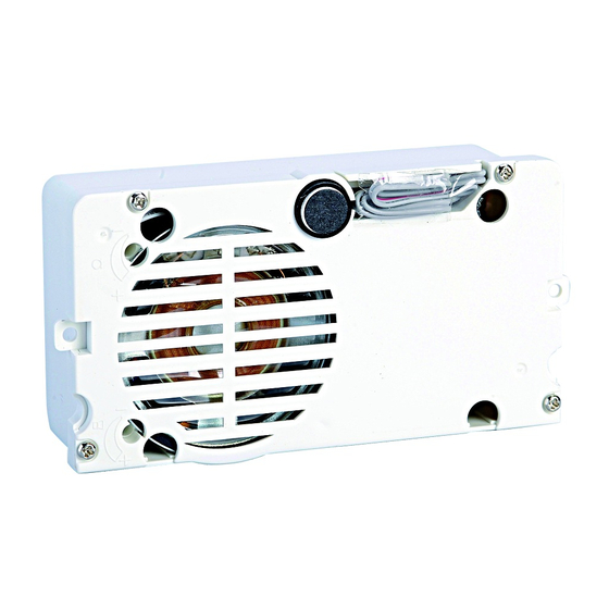
Comelit 1622 Technical Manual
Audio module
Hide thumbs
Also See for 1622:
- Technical manual (20 pages) ,
- Technical instructions (14 pages) ,
- Technical manual (20 pages)
Table of Contents
Advertisement
Quick Links
Advertisement
Table of Contents

Summary of Contents for Comelit 1622
- Page 1 TECHNICAL MANUAL Audio module Art. 1622 and Art. 1622L...
-
Page 2: Table Of Contents
Do not tamper with the internal elements offering protection against short circuits and overcurrents. • All the equipment must only be used for the purpose it was designed for. Comelit Group S.p.A. declines any responsibility for improper use of the apparatus, for any alterations made by others for any reason or for the use of non-original accessories or materials. -
Page 3: Description
Description 4. 5. 1. DIP switches for function programming and setting the 6. Terminal block for connection: user code. electric lock connection COM common relay contact 2. Switch for input/output programming. NC normally closed relay contact 3. Loudspeaker volume control. NO normally open relay contact GND input reference negative for DO-RTE 4. -
Page 4: Installation Information
4888 or Art. 4888C) when installing these risers. • Modules Art. 1622/Art. 1622L normally function as a main external unit (timed busy signal). • To set them as a secondary external unit (busy signal active for the whole time the riser is in use), set all the selector DIP switches to ON. -
Page 5: Installation With Ikall External Unit
Installation with Ikall external unit BLUE WHITE Nameplate LED lighting selection. Alternative microphone position (excluding 4 module entrance panel) open Speaker adjustment close... -
Page 6: Installation With Vandalcom (A) Roma (B) External Unit
Installation with Vandalcom (A) Roma (B) external unit white green orange white green orange Vandalcom (A) orange white green Roma (B) orange white green... -
Page 7: Button Programming
Button programming 33433 33434 Set the user code using the 33436 33433 dip switches; see “Dip switch 33434 programming table”. 33436... -
Page 8: Dip Switch Programming Table
Dip switch programming table Dip switch Dip switch Dip switch Name Name Name 1,5,6 1,6,7 2,5,6 2,6,7 1,2,5,6 1,2,6,7 3,5,6 3,6,7 1,3,5,6 1,3,6,7 2,3,5,6 2,3,6,7 1,2,3 1,2,3,5,6 1,2,3,6,7 4,5,6 4,6,7 1,4,5,6 1,4,6,7 2,4,5,6 2,4,6,7 1,2,4 1,2,4,5,6 1,2,4,6,7 3,4,5,6 3,4,6,7 1,3,4 1,3,4,5,6 1,3,4,6,7 2,3,4... -
Page 9: Example: Dip Switch Setting For Code 200
Dip switch Dip switch Dip switch Name Name Name 1,5,8 1,5,6,8 1,5,7,8 2,5,8 2,5,6,8 2,5,7,8 1,2,5,8 1,2,5,6,8 1,2,5,7,8 3,5,8 3,5,6,8 3,5,7,8 1,3,5,8 1,3,5,6,8 1,3,5,7,8 2,3,5,8 2,3,5,6,8 2,3,5,7,8 1,2,3,5,8 1,2,3,5,6,8 1,2,3,5,7,8 4,5,8 4,5,6,8 4,5,7,8 1,4,5,8 1,4,5,6,8 1,4,5,7,8 2,4,5,8 2,4,5,6,8 2,4,5,7,8 1,2,4,5,8 1,2,4,5,6,8 1,2,4,5,7,8 3,4,5,8... -
Page 10: Special Programming
Special programming 1 sec Set the dip switches for the function you wish to program, see “Special programming table”. -
Page 11: Special Programming Table
Special programming table CODE DIP SWITCH ON FUNCTIONS Audio-visal messages (Art. 1622L only) 2,5,7,8 visual messages only (Art. 1622L only) 1,2,5,7,8 Swedish (Art. 1622L only) 2,3,5,7,8 OFF (default) (Art. 1622L only) 1,2,3,5,7,8 Italian (Art. 1622L only) 4,5,7,8 French (Art. 1622L only) 1,4,5,7,8 Spanish (Art. - Page 12 Reset after lock-release in audio: disabled 1,4,5,6,7,8 Call transmission: single (default) 2,4,5,6,7,8 Call transmission: triple 1,5,6,7,8 Gestione posti interni collegati all'Art. 1622: fino a 70 (default) 2,5,6,7,8 Gestione posti interni collegati all'Art. 1622: da 71 a 100 System mode Simplebus (default) 1,2,3,4,5,6,7,8...
-
Page 13: Operating Distances With Art. 1595
Operating distances with Art. 1595 1622 1595 Operating distances A MAX B MAX 1 mm² (Ø 1,2 mm AWG 17) 50 m 500 m (165 feet) (1625 feet) 0,28 mm² (Ø 0,6 mm AWG 23) 300 m (15 feet) (990 feet) 0,5 mm²... -
Page 14: Wiring Diagrams
Wiring diagrams Door-entry phone system with 1 audio port, Ikall series. Switching on/voltage check with system in standby. 1595 120-230V 26-28 Vdc SB/TNP Local lock release button. -
Page 15: Door-Entry Phone System With 2 Audio Ports, Ikall Series
Door-entry phone system with 2 audio ports, Ikall series 1595 1595 120-230V 120-230V Local lock release button. SBC/014NP... -
Page 16: Wiring Diagram For System With Digital Call Module Art. 3360
Wiring diagram for system with digital call module Art. 3360 1595 120-230V Local lock release button. SB/QNP Wiring diagram with safety lock 1595 120-230V Local lock release button. SB2/SNP... -
Page 17: Using The External Unit Relay On Lock-Release Or Actuator Control
Set the dip switches permanently as shown in the figure (Dip switch ON 8, Dip switch OFF 1,2,3,4,5,6,7) Applies to Art. 1622L. Applies to Art. 1622 with R.I. 038 or greater Local lock release button. SB/RTNP Door open indication use variant... -
Page 18: Protection Device Connection Variant For Line Art. 1237
Protection device connection variant for line Art. 1237 1595 120-230V Local lock release button. SB2V/SCA Use of RC network for lock filter on relay contacts On C. NO On C. NC Excluded: voltage-free Jumper contacts. contacts. contact... - Page 20 w w w . c o m e l i t g r o u p . c o m Via Don Arrigoni, 5 - 24020 Rovetta (BG) - Italy...


