Table of Contents
Advertisement
Quick Links
Advertisement
Table of Contents

Related Manuals for Planet IVC-2004PT


Summary of Contents for Planet IVC-2004PT
- Page 1 PoE Industrial Ethernet Extender IVC-2004PT User’s Manual...
- Page 2 PLANET has made every effort to ensure that this User’s Manual is accurate; PLANET disclaims liability for any inaccuracies or omissions that may have occurred.
- Page 3 Do not dispose of WEEE as unsorted municipal waste and have to collect such WEEE separately. Revision PLANET PoE Industrial Ethernet Extender User's Manual For Model: IVC-2004PT Rev 2.0 (March, 2014) Part No.: 2350-AH0350-003...
-
Page 4: Table Of Contents
2.1.2 DIP Switch Indication ..........13 2.2 The Upper Panel ..............14 3. Installation ................15 3.1 Installing PoE Industrial Ethernet Extender – IVC-2004PT ..15 3.2 IVC-2004PT BNC / RJ-11 Proper Connection ......16 3.3 IVC-2004PT Application Connection ........17 3.4 Wiring the Power Inputs .............20 3.5 Wiring the Fault Alarm Contact ...........21... -
Page 5: Introduction
Symmetric means upstream and downstream rate are similar) – the VDSL port can be RJ-11 or BNC Connector. The IVC-2004PT can set to Master or Slave mode via a DIP switch. When IVC-2004PT (RJ-11) is connected with... - Page 6 With 4 PoE interfaces, the IVC-2004PT will be ideal for small businesses and workgroups requiring to deploy the PoE for the wireless access points, IP-based surveillance camera or IP phones in any places easily, efficiently and cost-effectively. The IVC-2004PT PoE Industrial Ethernet Extender with the IP-30 aluminum metal shape is designed for easy deployment in Heavy Industrial demanding environments.
-
Page 7: Key Features
1.3 Key Features The PoE Industrial Ethernet Extender provides the following key features: z 4-port IEEE 802.3af Power over Ethernet Standard z Each PoE port provides 15.4 watts z Compatible with IVC-2002, VC-201A and VC-202A (17a Profile) z Cost-effective VDSL2 Master / Slave bridge solution via DIP Switch z Selectable BNC and RJ-11 mode for the data transmission z -40 to 75 degrees C operating temperature z Redundant Power Design: 24V or 48V DC, redundant power with... -
Page 8: Specifications
1.4 Specifications Product IVC-2004PT Hardware Specifications 10/100 Base-TX 4 x RJ-45, Auto-Negotiation and Auto-MDI/MDI-X 4 x PoE (Port1 ~ Port4) Ports 1 x RJ-11, female Phone Jack VDSL 1 x BNC, female connector DIP Switch 4 position DIP switch Master / Slave mode select... - Page 9 • 10Base-T: 2-pair UTP Cat.3,4,5 up to 100m (328ft) Ethernet • 100Base-TX: 2-pair UTP Cat.5, 5e, 6 up to 100m (328ft) Cabling Twisted-pair telephone wires (AWG24 or better) VDSL (RJ-11) up to 1.4km 50 ohm: RG58A/U, RG58C/U, RG58/U and 75 ohm: RG6 (Distance 2.4km) Asymmetric Mode VDSL (RJ-11)
- Page 10 Dimensions (H x W x D) 135mm x 87.8mm x 50mm Weight 631g 24V or 48V DC for PoE Devices Power Requirements Redundant power with polarity reverse protection function Power Consumption / 66.4 watts / 226BTU max. (PoE) Dissipation 5.64 watts / 19.24BTU (non-PoE) Installation DIN Rail Kit and Wall-mount Ear Standard Conformance...
-
Page 11: Hardware Description
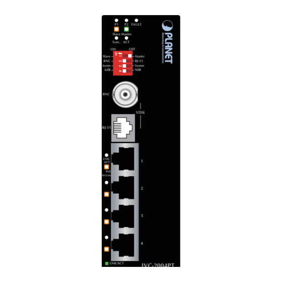
2. Hardware Description z IVC-2004PT The IVC-2004PT provides 4 RJ-45 with PoE, 1 RJ-11 and 1 BNC port for network line connection. The 4 RJ-45 ports come with two different running speeds – 10Mbps and 100Mbps. It will distinguish the speed of incoming connection automatically. -
Page 12: Led Indicators For Ivc-2004Pt
2.1.1 LED Indicators for IVC-2004PT The diagnostic LEDs on the front panel provide the operating status of individual port. z System Color Function Green Light Indicates power 1 has power. Green Light Indicates power 2 has power. Indicates either power 1 or power 2 has no... -
Page 13: Dip Switch Indication
Slave mode, the DIP switch 2, 3 and 4 are non-func- tional. Note z Link Type t BNC mode allows IVC-2004PT to connect and transfer data by using BNC cable t RJ-11 mode allows IVC-2004PT to connect and transfer data by using Telephone Wire... -
Page 14: The Upper Panel
z Band Plan t User can switch the Band Plan either Symmetric or Asymmetric by their own. When Symmetric is selected, it provides better upstream performance. When Asymmetric is selected, it provides better downstream performance. Please refer to the above table for details. -
Page 15: Installation
The PoE Industrial Ethernet Extender has some limitation as mentioned below: IVC-2004PT: The device is used for Point-to-Point connection only (Master device to Slave device) and has equipped with one RJ-11 and one BNC connector for VDSL2 network connection. -
Page 16: Ivc-2004Pt Bnc / Rj-11 Proper Connection
3.2 IVC-2004PT BNC / RJ-11 Proper Connection PLANET PoE Industrial Ethernet Extender has a DIP switch which can adjust to be Master or Slave mode. As to connection of two PLANET PoE Industrial Ethernet Extenders, one must be Master (CO) mode and the other one must be Slave (CPE) mode. -
Page 17: Ivc-2004Pt Application Connection
* BNC: 2.4km LAN 2 RJ-11: 1.4km Figure 3-2: IVC-2004PT BNC and RJ-11 Connection With 4 PoE, in-line power interfaces, the PoE Industrial Ethernet Extender can build a power central-controlled IP phone system, IP camera system, and AP group for the enterprise. For instance,... - Page 18 PoE VoIP Phone Figure 3-3: IVC-2004PT PoE Connection The IVC-2004PT temperature range is from -40 to 75 degrees C which can handle any harsh environment and places. It is also compatible with PLANET IVC-2002, VC-201A and VC-202A, without spending extra cost to deploy a new local Internet in an apartment, hotel, campus and hospitality environment.
- Page 19 VDSL2 Telephone Wire VDSL2 Figure 3-4: IVC-2004PT Application Topology To decide where to put the IVC-2004PT, you must ensure: t It is accessible and cables can be connected easily. t Cabling is away from sources of electrical noise such as radios, transmitters and power lines and fluorescent lighting fixtures t Water or moisture must be avoided.
-
Page 20: Wiring The Power Inputs
3.4 Wiring the Power Inputs The 6-contact terminal block connector on the top panel of PoE Industrial Ethernet Extender is used for two DC redundant power inputs. Please follow the steps below to insert the power wire. 1. Insert positive / negative DC power wires into contacts 1 and 2 for POWER 1, or 5 and 6 for POWER 2. -
Page 21: Wiring The Fault Alarm Contact
2. Tighten the wire-clamp screws for preventing the wires from loos- ening. Power 1 Fault Power 2 3.5 Wiring the Fault Alarm Contact The fault alarm contacts are in the middle of the terminal block connector as the picture shows below. Inserting the wires, the PoE Industrial Ethernet Extender will detect the fault status of the power failure and then forms an open circuit. -
Page 22: Mounting Installation
Extender and make connection to it. Please read the following topics and perform the procedures in the order being presented. In the installation steps below, this Manual uses IGS-801 (PLANET 8-port Industrial Gigabit Switch) as an example. However, the steps for PLANET Industrial Switch and Note Industrial Media Converter are similar. - Page 23 Step 1: Lightly press the button of the DIN-Rail to put it onto the track. Step 2: Check whether the DIN-Rail is tightly on the track. Step 3: Please refer to the following procedures to remove the PoE Industrial Ethernet Extender from the track. Step 4: Lightly press the button of the DIN-Rail to remove it from the track.
-
Page 24: Wall Mount Plate Mounting
z 3.6.2 Wall-mount Plate Mounting To install the PoE Industrial Ethernet Extender on the wall, please follow the instructions described below. Step 1: Remove the DIN-Rail from the PoE Industrial Ethernet Extender; loose the screws to remove the DIN-Rail. Step 2: Place the wall-mount plate on the rear panel of the PoE Industrial Ethernet Extender. -
Page 25: Troubleshooting
2.4km for BNC and 1.4km for RJ-11 connections. Please also try to set the DIP switch of the IVC-2004PT to the other SNR mode. 2. Please note that you must use one IVC-2004PT in Master mode and the other IVC-2004PT in Slave mode. SYMPTOM: TP LED does not light after cable is connected to the port. -
Page 26: Faq
91/99Mbps 21/10Mbps 95/99Mbps 19/13Mbps Q5: Is IVC-2004PT compatible with VC-201A / VC-202A? A5: Yes, IVC-2004PT (profile 17a) and VC-201A / VC-202A (profile 17a) are based on ITU-T G.993.2 VDSL2 with the same profile; so far they are compatible with each other. - Page 27 Q6: What is SNR and what’s the effect? A6: In analog and digital communications, Signal-to-Noise Ratio, often written as SNR, is a measure of signal strength relative to back- ground noise. The ratio is usually measured in decibels (dB). In digital communications, the SNR will probably cause a reduc- tion in data speed because of frequent errors that require the source (transmitting) computer or terminal to resend some packets of data.
- Page 28 *Model Number: IVC-2004PT * Produced by: Manufacturer‘s Name : Planet Technology Corp. Manufacturer‘s Address: 10F., No.96, Minquan Rd., Xindian Dist., New Taipei City 231, Taiwan (R.O.C.) is herewith confirmed to comply with the requirements set out in the Council Directive on the Approximation of the Laws of the Member States relating to Electromagnetic Compatibility Directive on (2004/108/EC).