Webasto thermo top evo Workshop Manual
Petrol/diesel
Hide thumbs
Also See for thermo top evo:
- Installation documentation (64 pages) ,
- Manual (57 pages) ,
- Installation instructions manual (48 pages)

Related Manuals for Webasto thermo top evo


Summary of Contents for Webasto thermo top evo
-
Page 1: Water Heaters
Visit www.butlertechnik.com for more technical information and downloads. Water Heaters Workshop Manual Thermo Top Evo Type Thermo Top Evo (Petrol) Type Thermo Top Evo (Diesel) 03/2003 www.butlertechnik.com... - Page 2 Only genuine Webasto parts may be used. See also Webasto air and water heaters accessories catalogue. NEVER try to install or repair Webasto heating or cooling systems if you have not completed a Webasto training course, you do not have the necessary technical skills and you do not have the technical documentation, tools and equipment available to ensure that you can complete the installation and repair work properly.
-
Page 3: Table Of Contents
Visit www.butlertechnik.com for more technical information and downloads. Thermo Top Evo Table of Contents Table of Contents Introduction ................101 Contents and purpose. - Page 4 Table of Contents Thermo Top Evo Circuit diagrams............... 701 Servicing work .
- Page 5 Fig. 701 Wiring diagram of Thermo Top Evo parking heater and 12 V digital timer......702 Fig. 801 CO2 setting values .
- Page 6 Visit www.butlertechnik.com for more technical information and downloads. List of illustrations Thermo Top Evo www.butlertechnik.com...
-
Page 7: Introduction
This heading is used to highlight operating instructions or procedures which, if not or not correctly followed, may The Thermo Top Evo water heater was designed for instal- result in damage to the equipment or its components. lation in Class M1 motor vehicles. The installation in motor... -
Page 8: Spare Parts
Non-compliance with the installation/operating instruc- tions and the warnings contained therein will lead to the exclusion of all liability by Webasto. The same ap- plies if repairs are carried out incorrectly or with the use of parts other than genuine spare parts. This will result in the invalidation of the type approval for the heater and therefore of its homologation/EC type licence. -
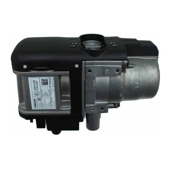
Page 9: General Description
– to preheat water-cooled vehicle engines. vehicle manufacturer. The Thermo Top Evo auxiliary heater can be upgraded to a parking-auxiliary heater with an additional kit. The heater designed according to the evaporator principle operates in the full-load and partial-load mode, controlled As the external appearance is identical, the heaters are by the temperature sensor. -
Page 10: Combustion-Air Fan Unit/Control Unit
Visit www.butlertechnik.com for more technical information and downloads. 2 General description Thermo Top Evo Combustion-air fan unit/control unit The combustion-air fan unit contains: • the heater type label • the connection piece for the combustion air pipe • the control unit with the plug-in contacts •... -
Page 11: Glow Plug/Flame Monitor
Visit www.butlertechnik.com for more technical information and downloads. Thermo Top Evo 2 General description 2.2.1 Glow plug/Flame monitor 2.3.1 Temperature sensor and overheating sensor The glow plug/flame monitor is connected to the control The temperature sensor detects the coolant temperature in unit (SG) via an electrical line with a connector (B9). -
Page 12: Heater Controls
Thermo Top Evo IMPORTANT Only the model DP42 fuel metering pump may be used for the Thermo Top Evo heater. Observe the model designation on the component for this purpose. When replacing the metering pump, the CO settings must be checked. See Section 8.2. -
Page 13: Description Of Operation
(below 5 °C) and engine running. delivery, etc.). NOTE The Thermo Top Evo heaters described in this manual can Heating mode only be put into operation with a W-bus-capable heater control, or with the Webasto Thermo Test PC Diagnosis. -
Page 14: Restarting After Fault Lock-Out
Commissioning must them be carried out with the Webasto Thermo Test PC Diagnosis. Prime the heater with fuel using the Webasto Thermo Test PC Diagnosis: Press the fill line button and fill the lines until fuel is present at the heater. -
Page 15: Technical Data
Visit www.butlertechnik.com for more technical information and downloads. Thermo Top Evo 4 Technical data Technical data The technical data is contained in the installation instructions. www.butlertechnik.com... - Page 16 Visit www.butlertechnik.com for more technical information and downloads. 4 Technical data Thermo Top Evo Page for notes www.butlertechnik.com...
-
Page 17: Troubleshooting
The heater faults stored in the fault memory must be read out and printed with the Webasto Thermo Test PC Diagno- 5) If a fault from 4) occurs 6 times consecutively without sis. To delete the heater lock-out without clearing the fault... -
Page 18: Reading Out Fault Memory
Reading out fault memory The fault memory of the heater can be read out with the Webasto Thermo Test PC Diagnosis. The fault memory displays up to 8 different faults. The older an fault is, the higher its number. The current operating duration and the current start-up number are entered in the control unit summary. -
Page 19: Component Fault Entered In The Fault Memory
Visit www.butlertechnik.com for more technical information and downloads. Thermo Top Evo 5 Troubleshooting Component fault entered in the fault memory Fault Fault WTT* fault message Fault details with double- Recommended workshop code code click in WTT* action (HEX) (DEZ) No fault... - Page 20 Visit www.butlertechnik.com for more technical information and downloads. 5 Troubleshooting Thermo Top Evo Fault Fault WTT* fault message Fault details with double- Recommended workshop code code click in WTT* action (HEX) (DEZ) The glow/ignition-ele- Glow plug resistance is outside In case of multiple occur-...
- Page 21 Overheat sensor interrupted or Conduct electrical test of tion short circuit to supply voltage temperature sensors (see Section 5.7, Fig. 504, Point 7) Fig. 501 Overview of component faults entered in the fault memory * WTT = Webasto Thermo Test PC Diagnosis www.butlertechnik.com...
-
Page 22: General Faults Entered In Fault Memory
Visit www.butlertechnik.com for more technical information and downloads. 5 Troubleshooting Thermo Top Evo General faults entered in fault memory Fault Fault WTT* fault message Fault details with double- Recommended workshop code code click in WTT* action (HEX) (DEZ) No error... - Page 23 Visit www.butlertechnik.com for more technical information and downloads. Thermo Top Evo 5 Troubleshooting Fault Fault WTT* fault message Fault details with double- Recommended workshop code code click in WTT* action (HEX) (DEZ) ECU wrong coded Incorrect parameter block or This fault can only occur on...
- Page 24 Visit www.butlertechnik.com for more technical information and downloads. 5 Troubleshooting Thermo Top Evo Fault Fault WTT* fault message Fault details with double- Recommended workshop code code click in WTT* action (HEX) (DEZ) Initial starting attempt failed No additional information In case of frequent occurrence available (>...
- Page 25 Visit www.butlertechnik.com for more technical information and downloads. Thermo Top Evo 5 Troubleshooting Fault Fault WTT* fault message Fault details with double- Recommended workshop code code click in WTT* action (HEX) (DEZ) Customer specific fault 3 No additional information In case of frequent occurrence available (>...
- Page 26 (see repeating telegram four Section 5.7, Fig. 504, Point 2, times) 3 and 4) Fig. 502 Overview of general faults entered in fault memory * WTT = Webasto Thermo Test PC Diagnosis www.butlertechnik.com...
-
Page 27: Faults Without Fault Entry In Control Unit
Possible faults Before each repair on the heater, the fault memory must be read out with the Webasto Thermo Test PC Diagnosis. Exist- The overview only shows some of the possible faults. The ing faults must be printed before deleting and made availa- Webasto Service Hotline must be contacted in individual ble to the Webasto Hotline or the Warranty Department. -
Page 28: Fig. 504 Overview Of Functional Test Of Heater And Its Components
20 ± 2 °C Petrol feed rate: Metering pump 7 Hz, 60 sec: 11.6 to 14.3 ml Measure feed rate with Webasto Thermo Test PC Diagnosis, also see Section 8.4 Diesel feed rate: 7 Hz, 60 sec: 12.0 to 14.6 ml... - Page 29 Component Recommended workshop action Parameter Conduct component test to check function of circu- Touch with hand; pump lating pump with Webasto Thermo Test PC Diagno- functions if slight vibration sis. can be felt Circulating Measure resistance on circulating pump connector 10 ±...
- Page 30 5 Troubleshooting Thermo Top Evo Fault Component Recommended workshop action Parameter Read out fault memory with Webasto Thermo Test PC Diagnosis, then print out and clear fault memory Control unit Include printed fault log when sending heater to (fault memory) Webasto.
- Page 31 Visit www.butlertechnik.com for more technical information and downloads. Thermo Top Evo 5 Troubleshooting Page for notes www.butlertechnik.com...
- Page 32 Visit www.butlertechnik.com for more technical information and downloads. 5 Troubleshooting Thermo Top Evo www.butlertechnik.com...
-
Page 33: Operating Tests
Visit www.butlertechnik.com for more technical information and downloads. Thermo Top Evo 6 Operating tests Operating tests General This section describes the tests of the heater and its compo- nents in the installed and the removed state. Operating checks in vehicle 1. - Page 34 Visit www.butlertechnik.com for more technical information and downloads. 6 Operating tests Thermo Top Evo Page for notes www.butlertechnik.com...
- Page 35 Visit www.butlertechnik.com for more technical information and downloads. Thermo Top Evo 7 Circuit diagrams Circuit diagrams Fig. 701 shows the circuit of the Thermo Top Evo heater, parking heater and heater control. Legend for wiring diagram. Cable colours blue brown...
-
Page 36: Fig. 701 Wiring Diagram Of Thermo Top Evo Parking Heater And 12 V Digital Timer
Visit www.butlertechnik.com for more technical information and downloads. 7 Circuit diagrams Thermo Top Evo Fig. 701 Wiring diagram of Thermo Top Evo parking heater and 12 V digital timer. www.butlertechnik.com... -
Page 37: Servicing Work
The CO measurement and setting must be carried out in the full load heater operating mode (display in Webasto Thermo Test: Full Load). The CO value is corrected in selec- Work on the heater tion point 2.7.1. -
Page 38: Dp42 Metering Pump
Conduct operating test of heater as described in section of the metering pump in accordance with the general instal- 6.2. lation instructions for the Thermo Top Evo. The Thermo Top Evo heater may only be operated with the DP42 metering Heater, removal and installation pump. -
Page 39: Installation
Webasto Thermo Test PC Diagnosis. With the fuel line completely drained, the line must be filled with the Webasto Thermo Test PC Diagnosis: Press the fill line button and prime line with fuel until fuel is present at the heater. - Page 40 Visit www.butlertechnik.com for more technical information and downloads. 8 Servicing work Thermo Top Evo Page for notes www.butlertechnik.com...
-
Page 41: Repair
A3 = Retaining plate B = Burner unit A4 = Water connection piece G1 = Fan housing A5 = O-ring SG = Control unit A6 = Screw W1= Heat exchanger A7 = Gasket Fig. 901 Component illustration of Thermo Top Evo heater www.butlertechnik.com... -
Page 42: Dismantling Heater
Visit www.butlertechnik.com for more technical information and downloads. 9 Repair Thermo Top Evo Burner unit 9.1.1 Dismantling heater Loosen screw (A2, Fig. 901) and remove water connec- tion piece (A4) with retaining plate (A3) and O-rings (A5). Loosen heater cover (A1) at side detents on fan hous- ing (G1) with a screwdriver. -
Page 43: Installing Burner Unit
Mount gasket (A7) on positioning pins of fan housing (G1) with flat side facing fan housing (G1). Then proceed with the installation of the heat exchanger (W1) as described in Section 9.1.2. NOTE Carry out the "Reset glow plug" routine with the Webasto Thermo Test PC Diagnosis. www.butlertechnik.com... -
Page 44: Glow Plug/Flame Monitor
Visit www.butlertechnik.com for more technical information and downloads. 9 Repair Thermo Top Evo Glow plug/Flame monitor Fig. 908 Remove cooling flag Fig. 906 Burner unit with glow plug 9.3.1 Electrical test of glow plug The cold resistance must be tested by connecting contacts 1 and 2 of the connector from the glow plug to a multimeter. -
Page 45: Installing Glow Plug/Flame Monitor
Visit www.butlertechnik.com for more technical information and downloads. Thermo Top Evo 9 Repair 9.3.3 Installing glow plug/flame monitor Fig. 910 Installing glow plug Fig. 914 Installing glow plug Fig. 911 Installing cooling flag Fig. 912 Installing retaining spring Fig. 915... -
Page 46: Combustion-Air Fan Unit And Control Unit
Section 8.2. Only use a new glow plug during installation. Uninsulated Carry out the "Reset glow plug" routine with the Webasto areas of the glow plug cable must not touch and must not Thermo Test PC Diagnosis. -
Page 47: Temperature Sensor/Overheating Sensor
Visit www.butlertechnik.com for more technical information and downloads. Thermo Top Evo 9 Repair Temperature sensor/ verheating sensor 9.6.1 Removing temperature sensor/ overheating sensor For information on removing heater cover, see Section 9.1.1. Pull connectors of sensors out of control unit. -
Page 48: Water Connection Piece
Visit www.butlertechnik.com for more technical information and downloads. 9 Repair Thermo Top Evo Water connection piece A distinction is made between two different retaining 9.7.1 Installing water connection piece Variant plates. Variant A - without locking and Variant B - with lock- A - without lock ing of connection piece on retaining plate. -
Page 49: Packing, Storage And Shipping
Fig. 1001). The type label and the surface of the heater must be protected against damage with a suita- ble surface (e.g. cardboard). Fig. 1001 Preferred position for Thermo Top Evo heater for storage and transport 1001 www.butlertechnik.com... - Page 50 Visit www.butlertechnik.com for more technical information and downloads. 10 Packing, Storage and Shipping Thermo Top Evo Page for notes 1002 www.butlertechnik.com...
- Page 51 Visit www.butlertechnik.com for more technical information and downloads. www.butlertechnik.com...
- Page 52 Visit www.butlertechnik.com for more technical information and downloads. Webasto AG Postfach 80 D - 82132 Stockdorf Germany National: Hotline: 01805 93 22 78 (€ 0,14 aus dem deutschen Festnetz) Hotfax: 0395 5592 353 Hotmail: technikcenter@webasto.com www.webasto.de International: www.webasto.com http://dealers.webasto.com www.butlertechnik.com...