
Related Manuals for Honeywell hus-nvr-1032-e


Summary of Contents for Honeywell hus-nvr-1032-e
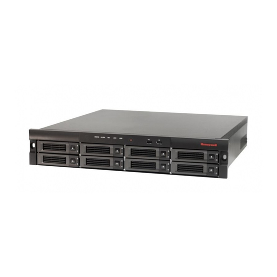
- Page 1 Honeywell HUS-NVR-1032-E 32CH Network Video Recorder User Guide Document 800-13326 Rev. A...
-
Page 3: Table Of Contents
Honeywell Contents About This Document ........................1 Overview of Contents ........................1 Special Fonts and Symbols ......................1 How to Use This Document ......................1 Introduction ............................ 3 Features ............................3 Specifications ........................... 4 Unpack Everything ........................... 5 Operating Keys ..........................6 Front View .......................... - Page 4 Honeywell Live ..............................26 Video Window Operation ......................28 Views Settings ......................... 28 Device Operation ........................30 Storage ............................ 37 PTZ Control ..........................40 Patrol ............................42 Playback ............................44 Video Window Operation ......................45 Search and Back Up ........................47 Filter ............................
-
Page 5: Important Safety Instructions
Honeywell Important Safety Instructions Before operating or installing the unit, read and follow all instructions. After installation, retain the safety and operating instructions for future reference. Electrical safety All installation and operation here should conform to local electrical safety codes. -
Page 7: About This Document
Honeywell 1 About This Document Thank you for purchasing the HUS-NVR-1032-E (32 Channel Network Video Recorder) NVR. This user guide describes the features, installation, configuration and operation of the HUS- NVR-1032-E, hereinafter referred to as “NVR”. Overview of Contents This user guide includes:... - Page 8 • The manual has been reviewed and its accuracy is guaranteed. If there is any uncertainty or controversy, please refer to the final explanation of Honeywell. Honeywell does not take any responsibility for any consequences caused by the misunderstanding of the manual or incorrect operations by the user.
-
Page 9: Introduction
Honeywell 2 Introduction This chapter provides the features and specifications of the NVR and introduces its front and rear panel keys. Features Real-time Surveillance • Supports real-time video on monitors via BNC, VGA and HDMI ports. • Supports 16 channels (D1) / 8 channels (720P) / 4 channels (1080P) video signal and one channel audio signal decoded simultaneously. -
Page 10: Specifications
Introduction Video Storage • 8 SATA HDD slots supporting hot plug. • 2 e-SATA ports to connect e-SATA disk or specified disk array (recomended). • Options on full HDD – Overwrite or Stop recording. • Video recordings are stored in specialized formats to prevent the data from being altered and guarantee its integrity. -
Page 11: Unpack Everything
Unpack Everything Before unpacking NVR, make sure that there is no visible damage on the box. Unpack the box, and check the accessories according to the ACCESSORY LIST below. Table 2-2 Accessory List Item Quantity HUS-NVR-1032-E (32 channels network video recorder) -
Page 12: Operating Keys
Introduction Power cord GIGA LAN CABLE, 3000mm, CAT-5E 6#-32 * 1/4 FM Accessories box M6*12 PB Quality certification Terminal Blocks Quick Guide Desiccant (SILICA) Remove the protective film on the NVR after the above procedures. Operating Keys Front View Figure 2-1 Front View Table 2-3 Name and Description of Keys (Front View) Symbol Name... -
Page 13: Rear View
Honeywell ALARM Alarm Indicator Flashes when an alarm occurs. Recording Indicator On – NVR is recording. LAN1 Network 1 Indicator Flashes when LAN1 is connected. LAN2 Network 2 Indicator Flashes when LAN2 is connected. HDD Tray Button Press to open the HDD tray. - Page 14 Introduction +12V DC +12V output, 500mA RS485 (Reserved) USB Port USB 2.0, for connecting USB devices. LAN1, LAN2 Network connection VGA Port Main video output/User interface RS232 Port Serial port HDMI Port Main video and audio output/User interface Storage Expansion by connecting storage devices e-SATA Port with this port Grounding Screw...
-
Page 15: Installation And Connections
Honeywell 3 Installation and Connections This chapter explains how to install the HDD and connect the NVR to related devices. • Attempting to open or disassemble the unit may expose you to dangerous voltage or other hazards and damage the unit. -
Page 16: Video And Audio Input/Output
Installation and Connections 3. Inset the HDD tray into the NVR. 4. Push the handle until it clicks into the lock. Video and Audio Input/Output Video Input The bandwidth for this NVR is 64Mbps; you can check the network information on the “System Status”... -
Page 17: Alarm Input/Output
Honeywell “MIC In” on the rear panel of NVR is for local audio input of the intercom system; “Audio out 2” is for local audio output. Proper settings to Intercom audio enable using active and passive microphones. Earphones and active loudspeakers can be connected to the intercom output interface. -
Page 18: Specifications Of Alarm Output Relay
Installation and Connections Specifications of Alarm Output Relay Table 3-2 Alarm Output Relay Model: HFD3 Rated switch capacity 2A 30VDC, 0.5A 125VAC Max switch power 62.5VA 60W Rating (Resistance load) Max switch voltage 250VAC, 220VDC Max switch current Open delay <4ms Close delay <4ms... -
Page 19: Usb Connection
Honeywell USB Connection There are two USB ports (5V 500mA) on the front panel and one on the rear panel for connecting USB devices. To ensure the NVR runs properly, do not connect USB devices which consume a lot of power. -
Page 20: Basic Operations
Basic Operations 4 Basic Operations This chapter provides basic configuration and operation information of NVR. Make sure that HDDs have been installed and all the cables are connected properly before turning on the NVR. Using the Mouse Connect the mouse to the USB port on the front panel or rear panel of the NVR. Refer to the following instructions for mouse operation: •... -
Page 21: Turning On
Honeywell Table 4-1 Mouse Operation Keyboard Input Method Icon Keyboard Operations Number • Click number/letter/symbol on the keyboard to input the corresponding character. Letter • Click to clear the previous (lower case) character. • Click to switch upper/lower case. •... -
Page 22: Default Accounts
Basic Operations After the system startup, the below figure is displayed: Figure 4-2 Language Setting Select “English” and click Next, the login window is displayed: Figure 4-3 Login Default Accounts There are three default accounts: Table 4-2 System Default Users User Name Password Default Authority... -
Page 23: Wizard
Honeywell Wizard “Wizard” helps user complete the basic setup for the system before the NVR starts working, including modifying the user password, setting the date and time, setting the network, formatting hard disk and adding devices, etc. When the “Wizard” is completed, the NVR could start working properly. - Page 24 Basic Operations Figure 4-5 Date & Time Time zone, date and time can be set on the above tab. Click Next to go to the “Network” tab as shown in the following figure: Figure 4-6 Network Settings-1 You can set IP address for the NVR on this tab. If select “Use the following IP address for LAN 1”, you should manually set “IP Address”, “Subnet Mask”...
- Page 25 Honeywell Figure 4-7 Network Settings-2 Click Apply to make the new network configuration take effect immediately. Click Next to go to the “Disk” tab as shown in the following figure: Figure 4-8 Disk To format the selected disk, click “Initialization…”. Click Next to go to “Device” tab as...
- Page 26 Basic Operations Figure 4-9 Device Click Import device table on “Device” tab (the device table template (.csv) is attached in the CD. You should first copy and edit the device table template file and save it to a USB device and connect the USB device to the NVR) and the “Import IPC Config (.csv) File”...
- Page 27 Honeywell Figure 4-11 Result of Import Check the target devices checkbox on the above window and click Next to go to “Recording Scenario”window as shown in the following figure: Figure 4-12 Scenario You can select “Record with high quality” or “Record with standard quality”on the above window.
-
Page 28: Switch User
Basic Operations Figure 4-13 Done Click Done to apply the new configurations. After applying the new configurations, the system will exit the wizard and display the Live screen, as shown in the following figure: Figure 4-14 Live Screen (First Login) Switch User To switch to another user, navigate to Switch User in the top left corner of Live... -
Page 29: Change Password
Honeywell Figure 4-15 Switch User Change Password To change the password of current user’s, navigate to Change Password in the top left corner of Live screen, and a window is displayed as shown in the following figure: Figure 4-16 Change Password Input old password, new password and confirm password and then click OK. -
Page 30: Restart
Basic Operations Figure 4-17 Log Off Restart To restart the system, navigate to Restart in the top left corner of the Live screen and click OK in the pop-up window as shown in the following figure: Figure 4-18 Restart After clicking OK, the screen displays a pop-up window and restarts several seconds later. Shutdown To shutdown the system, navigate to Shutdown in the top left corner of the Live... -
Page 31: Recovery (Power Failure)
Honeywell Figure 4-19 Shutdown Recovery (Power Failure) If the NVR crashes, restart the machine to resume the working condition. If the NVR is shut down abnormally during recording, the current recorded data might be lost. Replacing the Button Cell Battery It is recommended to use Lithium batteries of the same type (CR2032) to replace the old one. -
Page 32: System Operation And Configuration
System Operation and Configuration 5 System Operation and Configuration This chapter describes in detail how to view live video, play back, search and backup video and set system configurations, etc. Live When successfully logged in, the Live screen is displayed. On this screen, you can view live video, check alarm log, switch layout and scenario, manage cameras and disks, record manually, control PTZ, etc. - Page 33 Honeywell Click in the top left corner on the Live screen and the main menu is displayed as shown in the following figure: Figure 5-2 Main Menu Table 5-1 Menu Function Name Function Enter the “Search&Backup” screen. Refer to the “Search and Back...
-
Page 34: Video Window Operation
System Operation and Configuration Video Window Operation There are 6 (1/4/6/8/9/16 windows) window layouts. To switch the window layout, click “Window Layout” on top of the Live screen. Playing Live Video Drag the target camera icon from the“Devices” list to the target video window, or click the icon in the video window to select the target camera from the pop-up list to play the live video. -
Page 35: Creating A View
Honeywell Figure 5-3 Views List Creating a View Select a layout from the “Window layout”; Drag the target camera icon (up to 16 icons) from the “Deviecs” list to the video window; Click in the bottom right corner of the “Views” list and enter the view name in the pop-up “New View”... -
Page 36: Device Operation
System Operation and Configuration Figure 5-5 Editing Mode Refer to step 1 and 2 of “Creating a View” on page to edit. To give up editing, click When editing is done, click in the bottom right corner of the window and a pop-up window is displayed as shown in the following figure: Figure 5-6 Editing a View Click OK to save the change;... - Page 37 Honeywell Device name in gray—off line. indicates the camera is now recording. Figure 5-7 Devices List Adding a Camera Click in the bottom right corner of the “Devices” list and the “Add Devices” window is displayed as shown in Figure 5-8 and there are three tabs in the window: “Add”, “Search”...
- Page 38 System Operation and Configuration Figure 5-8 Add Camera If you want to set stream, PTZ and multicast, click “Advanced Settings” in the above window and the “Advanced Settings” window is displayed as shown in the following figure: Figure 5-9 Advanced Settings After the settings are finished, click OK and the added camera is displayed in the “Devices”...
- Page 39 Honeywell Figure 5-10 Search Camera Click Search and then all the cameras of this type are listed. Click to turn page down. Check the target camera checkbox. Click Quick Add, when the pop-up window is displayed, click OK to add the selected cameras to the “Devices” list; or click Next to...
- Page 40 System Operation and Configuration Click Import devices list and the “Import File” window is displayed as shown in the following figure: Figure 5-12 Import File Select USB device and target file (CVS file) and click OK to enter the “Choose Cameras”...
- Page 41 Honeywell Editing a Camera Select a camera in the “Devices” list (Figure 5-7) and click in the bottom right corner and the following screen is displayed. You can modify the camera’s access parameters on this screen. Figure 5-14 Editing a Camera If you want to set stream, PTZ and multicast, click “Advanced Settings”...
-
Page 42: Removing A Camera
System Operation and Configuration Figure 5-16 Success Click OK to close the window and exit. Configuring a Camera To configure the camera stream (Codec Type, Resolution, Frame Rate and Bit Rate), right click the icon of the camera and select “Camera Configuration” in the pop-up menu, the configuration window is shown as the following figure: Figure 5-17 Camera Configuration When the settings are finished, click Apply to save the new configuration and click Cancel... -
Page 43: Storage
Honeywell Manual Recording On the Live screen, you can manually start/stop recording on a camera. Start Manual Recording—Right click the icon of the camera and select RecordManual Recording. Stop Manual Recording—Right click the icon of the camera and select RecordStop Recording. - Page 44 System Operation and Configuration • It is recommended that to eject the disk by user interface operation, otherwise, it will damage the disk or cause data loss. • It is recommended that the ejection interval between two disks is not less than 30 seconds. Read/Write Type To set a disk to READ-ONLY, right click the disk icon and select SetRead-Only.
-
Page 45: Formatting Disk
Honeywell Formatting Disk To format a disk, right click the disk icon and select “Format” in the pop-up menu and then a pop-up window is displayed: Figure 5-21 Format Click OK and wait until the message pops up indicating it is successful. -
Page 46: Ptz Control
System Operation and Configuration Figure 5-23 Properties “S.M.A.R.T.Evaluation” has two indexes: “Pass”/Failed”; “Whole Evaluation” has three indexes: “Good”/ “Normal”/ “Poor”. If “Whole Evaluation” displays “Poor”, user should replace the disk to avoid the data loss. Click OK to close the window. PTZ Control PTZ function is only available for cameras equipped with PTZ device. -
Page 47: Save Preset
Honeywell Figure 5-25 PTZ Control Interface Figure 5-26 PTZ Control As shown in the above figure, click to get a zoomed in or zoomed out image; drag to adjust the shooting direction; click to choose “Go to Preset” or “Save Preset”. -
Page 48: Patrol
System Operation and Configuration Go To Preset Figure 5-28 Go To Preset To turn the camera to an existing preset, click to select “Go to Preset”, and click choose the target numeric figure in the box. Click Go. Click to exit PTZ control. Patrol Patrol function can circularly play groups of live videos. - Page 49 Honeywell Enter the Slide Name in the text box and click OK.The “Edit” window is displayed as shown in the following figure: Figure 5-31 Edit Patrol Click window layout icons in the top right corner to select the layout; Click...
-
Page 50: Playback
System Operation and Configuration To preview a patrol, select a patrol in the “Patrol List” (Figure 5-29) and click Preview, the “Patrol Preview” window is displayed as shown in the following figure: Figure 5-33 Patrol Preview Playing a Patrol To play a patrol, click on the Live screen and select a patrol in the dropdown list. -
Page 51: Video Window Operation
Honeywell on this screen: 1 window, 4 windows and full screen as shown in the following figure (4 windows): Figure 5-35 Playback Screen Video Window Operation Playback To play back video, drag the icon of the target camera from the “Devices” list to the video... -
Page 52: Playback Control
System Operation and Configuration Change the Aspect Ratio Right click the video window and select “Change the Aspect Ratio” in the pop-up menu to switch the aspect ratio of the current video window. Codec Type Right click the video window and select “Codec Type (H.264/MJPEG)” in the pop-up menu. Playback Control Playback control is at the bottom of this screen as in the figure below: Figure 5-36 Playback Control... -
Page 53: Search And Back Up
Honeywell Play the video at a lower speed. Each click on the button switches to a Speed Down different level of speed (2 levels: 1/4x and 1/2x). When the current speed is 1/4x, clicking the button again to restore to the normal speed. - Page 54 System Operation and Configuration Figure 5-38 Search & Back Up Specify the target time, camera, codec and event in the “Filter” window and the target video is displayed as shown in the below figure: Figure 5-39 Seach Result Select and drag the target video strip (marked with white dashed line) to specify the playback start time.
-
Page 55: Back Up Videos
Honeywell Back Up Videos Video clips can be backed up to an external USB storage device. There are two methods of backup: Back up on the Search&Backup screen: • Search the target video by conditions; see “Search Video” section on page 47. -
Page 56: View Log
System Operation and Configuration Figure 5-44 Export Video Clips on Playback Screen Select the window that the target camera represents (1, 2, 3 and 4 respectively represents the video window). Select the target device and format. Click Start to export the video clips. The video format is. -
Page 57: Alarm Log
Honeywell Figure 5-45 Operation Log Click to turn to the next page; click to skip to the last page. To skip to the designated page, click the cursor in the text box and scroll the mouse wheel to select the target page number and click Go. - Page 58 System Operation and Configuration Figure 5-46 Alarm Log Click on an unread log and the figure below is displayed: Figure 5-47 Log Expanded Click to play the live video of the related camera; click to play back the recorded video of the related camera. Click in the top right corner of “Alarm Log”...
- Page 59 Honeywell Figure 5-48 Alarm Log-Menu “Configure Trigger Profiles”, see the “Trigger Profiles (Alarm Recording)” section on page 59; “Configure System Alarm”, see the “System Alarm” section on page 70; Select “Export” to export the target log to the external USB device or click “Remove All” and...
- Page 60 System Operation and Configuration Figure 5-50 Input Alarm Log Click to go to the next page; click to skip to the last page. To skip to the designated page, click the text box and scroll the mouse wheel to select the target page number and click Go.
-
Page 61: System Status
Honeywell Click to go to the next page; click to skip to the last page. To skip to the designated page, click the text box and scroll the mouse wheel to select the target page number and click Go. Check the “Date&Time” in the top left corner to select the target date to be viewed in the pop-up calendar;... - Page 62 System Operation and Configuration Figure 5-53 Nerwork Status Click Receiving in the above window to view the parameters of data being received and click Transmitting (right next to Receiving button) to view the parameters of data being sent. Figure 5-54 Receiving/Sending Chart...
-
Page 63: Hard Disk Status
Honeywell In the above window, Y-axis represents the network flow (Mbps) and the X-axis represents the time (200 Ms). Figure 5-55 Bit Rate Chart In the above window, the column with grey writing represents the camera and the column with yellow writing represents the bitrate of the camera (Kbps). -
Page 64: Record Setup
System Operation and Configuration Record Setup This NVR supports manual recording, scheduled recording, panic recording and alarm recording. This section describes scheduled recording and alarm recording. For manual recording and panic recording, please refer to the “Manual Recording” section on page and the “Panic Recording”... -
Page 65: Trigger Profiles (Alarm Recording)
Honeywell Select a scenario under “My favorite scenario” and click , the following figure is displayed: Figure 5-58 Scenario Mode Target Day—Selects the day to be set in the dropdown list. 0~23—Represents 24 hours. Each square is for half an hour. - Page 66 System Operation and Configuration Figure 5-60 Configure Trigger Profiles New Profile Click New Profile and click in the pop-up “Alarm Device” window to add alarm device. Click on the added alarm device to select the trigger condition in the dropdown list; Click in “Triggered Device”...
-
Page 67: System Setup
Honeywell Figure 5-63 System Settings Set Pre-Recording and Post-Recording: Pre-Recording—starts recording a few seconds before triggered alarms; Post-Recording—continues recording a few seconds after the alarm event occurs. Click Save Profile in Figure 5-63. The new profile is displayed in the “Alarm Profile” list as... -
Page 68: System Settings
System Operation and Configuration Figure 5-65 General Settings In the above window, you can view and modify the settings of the “Current User”, “Audio”, “Network-Lan1”, “Date&Time”, etc. System Settings Click System Settings in Figure 5-65 to enter the System Settings screen and where there are 4 options: “Date and Time”, “Audio”, “System Management”... -
Page 69: System Management
Honeywell In the above window, you can set time zone, date, time and whether to synchronize with NTP automatically. Click Advanced Settings and the below window is displayed: Figure 5-68 Advanced Settings You can set date and time format, NTP server and port. - Page 70 System Operation and Configuration Figure 5-71 System Management You can upgrade firmware, restore to factory/default settings, export/import configuration file and enable auto log off. Upgrade Firmware Steps Copy the upgrade file (“.hdu” file) into a USB storage device and connect it to NVR. Click Upgrade Firmware in the window above.
-
Page 71: Display Settings
Honeywell Figure 5-73 Import Select the target file and then click OK to start importing the configuration file. When finished, the system will restart automatically to apply the new configuration. System Information Click “System Information” to view information such as model name, serial number, firmware version, etc., as shown in the following figure:... -
Page 72: User Settings
System Operation and Configuration Basic Click “Basic” to view and modify User Interface language, resolution and Local On-screen Display as shown in the following figure: Figure 5-76 Display Image Click “Image” and select HDMI/VGA or CVBS to modify image parameters as shown in the following figure: Figure 5-77 Image Parameters Patrol... - Page 73 Honeywell Figure 5-79 User Management New User Click New User in the above window and the “New User” window is displayed: Figure 5-80 New User Enter the User Name, Password, and select Role, click OK. • If a message pops up indicating the name already exists, it means the name entered for the new user has been occupied.
- Page 74 System Operation and Configuration Figure 5-81 Edit You can modify the “Role” in the above window. Remove User To remove a user, select a target user in the “User List” window (Figure 5-79) and click Remove. The three default users (guest, operator and admin) cannot be removed. Reset Password Click Reset Password in the above window to reset to default password.
-
Page 75: Network Settings
Honeywell Only “Administrator” user is able to manage role authority options. Network Settings Click Network Settings in Figure 5-65 to enter the Network Settings screen and where there are 3 options: “Basic”, “Multicast” and “HUS VMS” as shown in the following figure:... -
Page 76: Alarm Settings
System Operation and Configuration When changing the IP settings, it will stop the video tasks of current IE client and display a message, click OK to proceed and apply the new settings. Multicast To set a channel to multicast stream, click “Multicast” and the below window is displayed: Figure 5-85 Multicast In the above window, you can enable multicast, set the beginning IP address, etc. -
Page 77: Alarm Output
Honeywell Alarm Output Click “Alarm Output” to set “Trigger Type” and “Duration” as the figure below: Figure 5-88 Alarm Output Alarm Input Click “Alarm Input” to set the alarm input status as the figure below: Figure 5-89 Alarm Input... -
Page 78: Nvr Internet Explorer (Ie) Client
NVR Internet Explorer (IE) Client 6 NVR Internet Explorer (IE) Client NVR can be accessed and controlled from the IE Client via the network. On the IE Client, all the settings of NVR’s on-screen menu can be implemented except for “Wizard”, “Views”, “Patrol”... - Page 79 Honeywell Figure 6-1 Display Menu Bar On the browser menu bar, open ToolsInternet options and select the “Security” tab, as shown in the following figure. Figure 6-2 Internet Options—Security Click Custom Level… and the following window is displayed:...
- Page 80 NVR Internet Explorer (IE) Client Figure 6-3 Security Settings—Internet Zone Check the options marked in red frame as shown in the above figure. Click OK. Figure 6-2, select “Local Intranet” and click Custom Level…. The following window is displayed: Figure 6-4 Security Settings—Local Intranet Zone Check the options marked in red frame as shown in the above figure.
-
Page 81: Login
Honeywell Compatibility View Settings: Open Tools Compatibility View settings. The following window is displayed: Figure 6-5 Compatibility View Settings Deselect “Display Intranet sites in Comatibility View” and “Display all websites in Compatibility View”. Login Enter the IP address of the NVR in the address bar of Internet Explorer (e.g. -
Page 82: Playing Live Video
NVR Internet Explorer (IE) Client Figure 6-7 Login Select the user name and enter the password. Click Login. When successfully logged in, the Live screen is displayed. Playing Live Video Follow one of the operations below to play live video: •... -
Page 83: Local Record
Honeywell Local Record “Local Record” function is for Internet Explorer (IE) Client only. It can manually record the visible live video and save to the computer. Click (Record Setup) on the Live screen and select “Local Record” in the following... -
Page 84: Local Playback
NVR Internet Explorer (IE) Client Local Playback “Local Playback” function is for Internet Explorer (IE) Client only. It can play back the video clips that saved in the computer. Follow the operations below to play back local video clips: Drag the target camera icon from the“Devices” list to the target video window on the Playback screen. - Page 85 Honeywell Security, Your Partner of Choice Honeywell Security Honeywell Security Asia Pacific 35F Tower A, City Center, 100 Zun Yi Road, Shanghai 200051, China TEL +86 21 22196888 FAX +86 21 62370740 Honeywell http://www.asia.security.honeywell.com ©2013 Honeywell International Inc. All rights reserved.