Table of Contents
Advertisement
Quick Links
SERVICE MANUAL CHANGE NOTICE
Changes and corrections have been made to the Service Manual for the LX4 Diversity Receiver. To update
your Service Manual, remove the pages identified in the tables below and replace them with the pages at-
tached to this Change Notice. Note that there are no changes to pages not specifically identified in the tables
below.
LX4 DIVERSITY RECEIVER SERVICE MANUAL REVISION HISTORY
Release
Original
Revision 1
Revision 2
Revision 3
Revision 4
Revision 5
CHANGES EFFECTIVE NOVEMBER 18, 2002
these pages from the
LX4 Service Manual
Pages 14 & 23
E1999, Shure Incorporated
25–1008–1 (BK)
LX4 DIVERSITY RECEIVER
Part Number
25A1008
25B1008
25C1008
25D1008
25D1008
25D1008
REMOVE
Shure Brothers Incorporated
222 Hartrey Avenue
Evanston IL 60202-3696 U.S.A.
LX Wireless System
Date Code
QH
QL
SC
SI
TL
BK
these pages into the
LX4 Service Manual
Pages 14 & 23
Color
White
Pink
Tan
White
White
White
INSERT
Printed in U.S.A.
Advertisement
Table of Contents

Related Manuals for Shure LX4


Summary of Contents for Shure LX4
- Page 1 SERVICE MANUAL CHANGE NOTICE LX4 DIVERSITY RECEIVER Changes and corrections have been made to the Service Manual for the LX4 Diversity Receiver. To update your Service Manual, remove the pages identified in the tables below and replace them with the pages at- tached to this Change Notice.
-
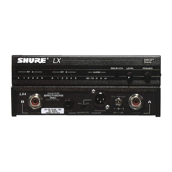
Page 2: Controls And Connectors
6. Power ON indicator Service Note: Shure recommends that all service procedures be performed by a Factory- Authorized Service Center or that the product be returned directly to Shure Brothers Inc. E1999, Shure, Inc. Licensing: Operation may require a user license. Frequency or power-output modifications Printed in U.S.A. -
Page 3: Circuit Description
A one quarter wavelength whip type antenna can be mounted direct- ly to the receiver or to a full rack panel (Shure model WA440), and can then be cabled to the receiver. Also, a Shure model WA404 antenna splitter can be used to provide antenna inputs and dc power to the LX4. -
Page 4: Squelch Control
Shure LX4 Diversity Receiver Diversity Control Signals The dc noise signals are compared by U3A, U3B, U3C, and U3D to produce diversity control signals. These signals directly control analog switches U6A and U6B, and diversity A/B LEDs D9 and D10. These switches control the flow of audio signals from U1A and U2A. - Page 5 Shure LX4 Diversity Receiver Independent Rf Sections Two complete, independent rf sections are provided for diversity reception. Signals enter the receiver via detachable, single-element quarter-wave antennas. For diversity channel A, they pass through a filter that is double-tuned by L100 and L101 before entering dual gate MESFET amplifier Q100.
- Page 6 Shure LX4 Diversity Receiver Power The Shure LX4 Diversity Receiver operates on 12.5 – 18 Vdc or from an ac power line with 120 Vac, 60 Hz external power converter; or 220 to 240 Vac, 50/60 Hz for export models. The dc power connector: is a male pin coaxial jack with locking connector.
- Page 7 Shure LX4 Diversity Receiver Test Component Locations 25D1008 (BK) Test Component Locations...
-
Page 8: Preliminary Tests
Shure LX4 Diversity Receiver Preliminary Tests Listening Test Before completely disassembling the receiver, operate it to determine whether it is functioning normally and try duplicating the reported malfunction. Refer to the User Guide for operating instructions, troubleshooting sugges- tions, and specifications. - Page 9 3. Remove the receiver’s antenna. Plug the test cable into the signal generator and the other end to the channel A antenna input. 4. Apply power to the LX4. 5. Verify that the unit unsquelches with rf signals greater than –89 dBm.
-
Page 10: Audio Tests
Shure LX4 Diversity Receiver Audio Tests NOTE: DC VOLTAGES ARE PRESENT AT MOST OUTPUTS RF TEST POINTS. USE A DC BLOCK ON THE HI Z POWER RF SIGNAL GENERATOR TO PROTECT TEST EQUIPMENT. LINE 12.5 – 18.9 VDC DC BLOCK... - Page 11 Shure LX4 Diversity Receiver NOTE: DC VOLTAGES ARE PRESENT AT MOST OUTPUTS RF TEST POINTS. USE A DC BLOCK ON THE HI Z POWER RF SIGNAL GENERATOR TO PROTECT TEST EQUIPMENT. LINE 12.5 – 18.9 VDC DC BLOCK RF SIGNAL GENERATOR...
-
Page 12: Disassembly And Assembly
Voltages in this equipment are hazardous to life. No user-serviceable parts are inside. Refer all servicing to qualified service personnel. The safety certifications of the LX4 Diversity Receiver do not apply when the operating voltage is changed from the factory setting. - Page 13 Shure LX4 Diversity Receiver Remove the printed circuit board (pcb): 1. Remove the nuts and washers from the antenna input connectors and the HI-Z audio output connector. 2. Remove the two screws on either side of the balanced output XLR connector.
-
Page 14: Service Procedures
Change the frequency by changing the crystal on the rf board. For proper operation, the crystal must be obtained from Shure and must operate within the frequency range of the pc board. Use the following equation to determine the operating frequency: Carrier frequency = 3 x (nominal crystal frequency in MHz) + 10.71 MHz... - Page 15 Shure LX4 Diversity Receiver Table 2 Wireless Frequency Selections Code Frequency Printed Circuit Board Assembly 169.445 169.505 170.000 170.245 170.305 171.045 171.105 171.845 171.905 173.800 174.100 174.400 174.500 175.000 176.200 176.600 177.000 177.600 180.400 182.000 182.200 183.200 183.600 184.600 186.200 186.350...
- Page 16 1. Solder a 33 kΩ resistor between TPA4 (TPB4) and ground for rf adjustments. Do the same for channel B with TPB4. 2. Set the rf signal generator frequency to the same as the LX4, with no modulation, and its amplitude at –60 dBm.
- Page 17 Deviation: none Amplitude: off Figure 4. RSSI Test Setup 1. Verify that the LX4 power is OFF. 2. Place a jumper between TPB7 and ground to mute channel B for channel A alignment. (Place a jumper between TPA7 and ground to mute channel A for channel B alignment.) 3.
- Page 18 Shure LX4 Diversity Receiver turns before full clockwise rotation, or 13 mm (1/4-inch) below the top of the can. Minimum inductance occurs when the core is level with the top of the can. Use care when turning the core to avoid locking it against the pcb and causing it to break.
-
Page 19: Audio Level Adjustments
(Place a jumper between TPA7 and ground to mute channel A for channel B alignment.) 1. Set the rf signal generator frequency to the same as the LX4, its modulation to FM, its modulation source to EXT, its FM deviation to 15 kHz, and its amplitude to –60 dBm. - Page 20 LO EXT LEDs on the rf signal generator are on. This amplitude should be between 1.4 and 1.5 V rms. 1. Set the rf signal generator frequency to the same as the LX4, its modulation to FM, its modulation source to EXT, its FM deviation to 15 kHz, and its amplitude to –60 dBm.
- Page 21 Shure LX4 Diversity Receiver Squelch Adjustment Test OUTPUTS POWER HI Z LINE 12.5 – 18.9 VDC DC BLOCK RF SIGNAL GENERATOR NOTE: DC VOLTAGES ARE PRESENT AT MOST RF TEST POINTS. USE A DC BLOCK ON THE RF SIGNAL GENERATOR TO PROTECT TEST EQUIPMENT.
-
Page 22: Power Input
Shure LX4 Diversity Receiver Bench Checks Power Input n Make sure that 10.0 ± 0.35 Vdc is present at TP9 (U7, pin 3). n If the voltage is lower than normal (but not zero), check for approximately 15 Vdc at the input of U7 (pin 1), a reversed electrolytic capacitor (C50), or a stage drawing excessive current. - Page 23 Shure LX4 Diversity Receiver n If the THD drops to an acceptable level, check the local oscillator frequency. Also, check FL100, FL101, FL200, and FL201 for polarity. n If the audio circuitry works correctly but the audio LEDs fail to light when the standard test signal is applied, or remain on when there is no modulation, check dc voltages at U11, and U4A.
-
Page 24: Parts Designations
Shure LX4 Diversity Receiver Replacement Parts and Drawings Parts Designations The following comments apply to the parts list and the schematic: Resistors: All resistors are surface-mount with rating and 1% tolerance. Capacitors: Unless otherwise noted, non-polarized capacitors are surface-mount dielectric types with a 100 capacity and a 5% tolerance, and polarized capacitors are tantalum types. - Page 25 Shure LX4 Diversity Receiver Table 4 Printed Circuit Board Components Shure Part Reference Designation Description Number D9,10,18 Surface mount LED, orange 184E18 D11,12,13,14,15,16,19, Surface mount LED, green 184D18 20,21,22,23,24,25,26 Surface mount LED, red 184A18 Output XLR connector, male 95A8598 Shrouded header...
- Page 26 Shure LX4 Diversity Receiver Table 5 Frequency Dependent Components Table Reference Shure Part Group Description Designation Number L103,203 Tunable coil 82B8003 L103,203 Tunable coil 82B8003 Tunable coil 82B8003 L103,203 L103,203 Tunable coil 82B8003 Tunable coil 82C8003 L103,203 L103,203 Tunable coil...
- Page 27 Shure LX4 Diversity Receiver LX4 Diversity Receiver: Printed Circuit Board Printed in U.S.A.
- Page 28 Shure LX4 Diversity Receiver * Note: On boards with pcb reference designator LX4 Diversity Receiver 34A8332E, the FM detector is 188A190. On Rf Section Schematic Diagram other boards, it is 188A129. Printed in U.S.A.
- Page 29 Shure LX4 Diversity Receiver LX4 Diversity Receiver Audio Section Schematic Diagram Printed in U.S.A.