Table of Contents
Advertisement
Thank you for choosing the A68HI AC/ A68HI Series (MS-7969 v1.X) Mini-ITX
motherboard. The A68HI AC/ A68HI Series motherboards are based on AMD A68H
chipset for optimal system efficiency. Designed to fit the advanced AMD FM2+/ FM2
processor, the A68HI AC/ A68HI Series motherboards deliver a high performance
and professional desktop platform solution.
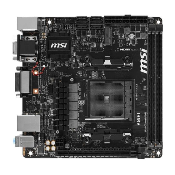
Layout
JUSB2
Top:1 PS/2 combo port
Bottom:2 USB 2.0 ports
Top:VGA port
Bottom:HDMI port
DVI port
Top: LAN Jack
Bottom: USB 3.0 ports
T:Line-In
M:Line-Out
JAUD1
B:Mic
JUSB1
SATA3
SATA4
JCI1
SYSFAN1
CPUFAN1
JPWR2
PCI_E1
SATA1 JFP2
SATA2
JFP1
M2_PCIE1
JTPM1
JPWR1
Advertisement
Table of Contents

Related Manuals for MSI A68HI ACSeries


Summary of Contents for MSI A68HI ACSeries
- Page 1 Thank you for choosing the A68HI AC/ A68HI Series (MS-7969 v1.X) Mini-ITX motherboard. The A68HI AC/ A68HI Series motherboards are based on AMD A68H chipset for optimal system efficiency. Designed to fit the advanced AMD FM2+/ FM2 processor, the A68HI AC/ A68HI Series motherboards deliver a high performance and professional desktop platform solution.
-
Page 2: Motherboard Specifications
Motherboard Specifications ■ AMD Socket FM2+ A-Series/Athlon™ Processors* Support * Also supports FM2 A-Series/Athlon™ Processors Chipset ■ AMD A68H Memory ■ 2x DDR3 memory slots support up to 32GB Support ■ Supports DDR3 2133/ 1866/ 1600/ 1333 MHz ■ Dual channel memory architecture ■... - Page 3 ■ Realtek RTL8111G Gigabit LAN controller ® WLAN & ■ Wi-Fi/Bluetooth expansion module with Intel Dual Band Bluetooth Wireless-AC 7260 chip*. - Supports Wi-Fi 802.11 a/b/g/n/ac, dual band (2.4GHz, 5GHz) up to 867 Mbps speed. - Supports Intel Wireless Display (WiDi) - Supports Bluetooth v4.0 (includes BLE** and Bluetooth 3.0+HS) * Only A68HI AC has a Wi-Fi/ Bluetooth module pre-installed.
-
Page 4: Back Panel
Back Panel A68HI AC Antenna PS/2 Mouse/ Keyboard Connector Line-In Line-Out USB 2.0 HDMI DVI-D USB 3.0 A68HI PS/2 Mouse/ Keyboard Line-In Line-Out USB 2.0 HDMI DVI-D USB 3.0 LAN LED Indicator LINK/ACT SPEED LED Status Description No link Link/ Activity LED Yellow Linked Blinking... -
Page 5: Apu & Heatsink Installation
APU & Heatsink Installation When installing a APU, always remember to install a APU heatsink. An APU heatsink is necessary to prevent overheating and maintain system stability. Follow the steps below to ensure correct APU and heatsink installation. Wrong installation can damage both the APU and the motherboard. - Page 6 Locate the APU fan connector on the motherboard. Position the cooling set onto the retention mechanism. Hook one end of the clip to hook first. Then press down the other end of the clip to fasten the cooling set on the top of the retention mechanism.
-
Page 7: Memory Installation
Memory Installation Important • DDR3 memory modules are not interchangeable with DDR2, and the DDR3 standard is not backward compatible. Always install DDR3 memory modules in DDR3 DIMM slots. • To ensure system stability, memory modules must be of the same type and density in Dual-Channel mode. -
Page 8: Internal Connectors
Internal Connectors JPWR1~2: ATX Power Connectors These connectors allow you to connect an ATX power supply. To connect the ATX power supply, align the power supply cable with the connector and firmly press the cable into the connector. If done correctly, the clip on the power cable should be hooked on the motherboard’s power connector. -
Page 9: Sata1~4: Sata Connectors
SATA1~4: SATA Connectors This connector is a high-speed SATA interface port. Each connector can connect to one SATA device. SATA devices include disk drives (HDD), solid state drives (SSD), and optical drives (CD/ DVD/ Blu-Ray). SATA1 SATA3 SATA2 SATA4 SATA1~4 (6Gb/s, by AMD A68H) Important •... -
Page 10: Cpufan1, Sysfan1: Fan Power Connectors
CPUFAN1, SYSFAN1: Fan Power Connectors The fan power connectors support system cooling fans with +12V. If the motherboard has a System Hardware Monitor chipset on-board, you must use a specially designed fan with a speed sensor to take advantage of the CPU fan control. Remember to connect all system fans. -
Page 11: Jfp1, Jfp2: System Panel Connectors
JFP1, JFP2: System Panel Connectors These connectors connect to the front panel switches and LEDs. When installing the front panel connectors, please use the optional M-Connector to simplify installation. Plug all the wires from the computer case into the M-Connector and then plug the M-Connector into the motherboard. - Page 12 JUSB2: USB 3.0 Expansion Connector The USB 3.0 port is backwards compatible with USB 2.0 devices. It supports data transfer rates up to 5Gbits/s (SuperSpeed). Important • Note that the VCC and GND pins must be connected correctly to avoid possible damage.
-
Page 13: Jbat1: Clear Cmos Jumper
JBAT1: Clear CMOS Jumper There is CMOS RAM onboard that is external powered from a battery located on the motherboard to save system configuration data. With the CMOS RAM, the system can automatically boot into the operating system (OS) every time it is turned on. If you want to clear the system configuration, set the jumpers to clear the CMOS RAM. -
Page 14: Entering Bios Setup
“GO2BIOS” tab on “MSI Fast Boot” utility screen to enable the system going to BIOS setup directly at next boot. Click "GO2BIOS" tab on "MSI Fast Boot" utility screen. Important Please be sure to install the “MSI Fast Boot” utility before using it to enter the BIOS setup. - Page 15 Overview After entering BIOS, the following screen is displayed. Temperature monitor Language System information Virtual OC Genie Button Boot device priority bar BIOS menu selection BIOS menu selection Menu display OC Menu Important • Overclocking your PC manually is only recommended for advanced users. •...
- Page 16 ▶ Current CPU/ DRAM Frequency These items show the current frequencies of installed CPU and Memory. Read-only. ▶ CPU Base Frequency (MHz) [Default] Sets the CPU Base clock. You may overclock the CPU by adjusting this value. Please note that overclocking behavior and stability is not guaranteed. This item appears when the installed processor supports this function.
- Page 17 ▶ Intel Extreme Memory Profile (XMP) [Disabled] XMP is the overclocking technology by memory module. This item will be available when you install the memory modules that support XMP technology. When the XMP is Enabled, the AMP will be forced to be disabled. [Disabled] Disables this function.
- Page 18 ▶ CPU Memory Changed Detect [Enabled] Enables or disables the system to issue a warning message during boot when the CPU or memory has been replaced. [Enabled] The system will issue a warning message during boot and than needs to load the default settings for new devices. [Disabled] Disables this function and keeps the current BIOS settings.
- Page 19 ▶ SVM Mode [Enabled] Enables or disables CPU Virtualization. [Enabled] Enables CPU Virtualization and allows a platform to run multiple operating systems in independent partitions. The system can function as multiple systems virtually. [Disabled] Disables this function. ▶ Core C6 State [Enabled] Enables or disables C6 state support.