Table of Contents
Advertisement
Quick Links
QQ
3 7 63 1515 0
SERVICE MANUAL
TE
L 13942296513
Caution
If electricity is connected during disassembly, it must be a no load current. If it is load
current, be sure to attach a heat sink to the power-amp IC. This will be damaged if the
above precautions are not followed, as it does not have a sub heat sink attached to it.
Contents
www
.
http://www.xiaoyu163.com
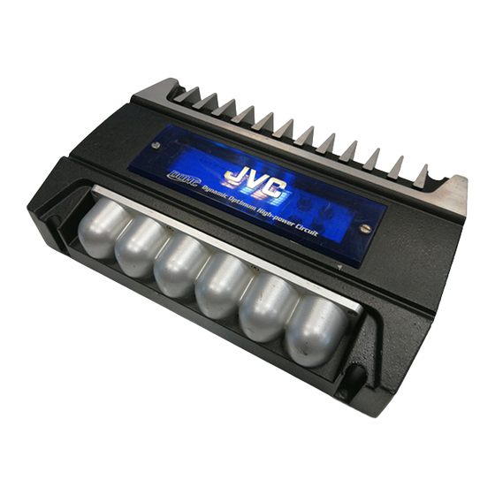
POWER AMPLIFIER
KS-AX6700
x
ao
u163
y
i
This service manual is printed on 100% recycled paper.
COPYRIGHT
2000 VICTOR COMPANY OF JAPAN, LTD.
http://www.xiaoyu163.com
2 9
8
3
6 7
1 3
1 5
1-2
1-3
1-5
1-8
1-9
co
.
KS-AX6700
9 4
2 8
Areas suffix
J -------- Nothem America
0 5
8
2 9
9 4
2 8
E ----- Continental Europe
m
No. 49559
Jun. 2000
9 9
9 9
Advertisement
Table of Contents

Related Manuals for JVC KS-AX6700


Summary of Contents for JVC KS-AX6700
-
Page 1: Table Of Contents
KS-AX6700 3 7 63 1515 0 SERVICE MANUAL POWER AMPLIFIER KS-AX6700 Areas suffix J -------- Nothem America L 13942296513 E ----- Continental Europe Caution If electricity is connected during disassembly, it must be a no load current. If it is load current, be sure to attach a heat sink to the power-amp IC. -
Page 2: Safety Precaution
KS-AX6700 Safety precaution 3 7 63 1515 0 ! CAUTION Burrs formed during molding may be left over on some parts of the chassis. Therefore, pay attention to such burrs in the case of preforming repair of this system. -
Page 3: Location Of Main Parts
KS-AX6700 3 7 63 1515 0 Location of main parts Volume knob Control panel Heat sink Switch knob L 13942296513 Heat sink Rear panel Fuse Output terminal Input for power Low input(R) Heat sink Front panel u163 High input connector Low input(L) http://www.xiaoyu163.com... - Page 4 KS-AX6700 3 7 63 1515 0 Heat sink (Bottom view) Main P.C. board GND wire Sub1 P.C. board L 13942296513 Main P.C. board 2pin connector Sub2 P.C. board (to CCFL P.C. board) Wire assemb'y (from Main) u163 CCFL P.C. board...
-
Page 5: Removal Of Main Parts
KS-AX6700 3 7 63 1515 0 Removal of main parts CAUTION: electricity connected during disassembly, it must be a no load current. If it is load current, be sure to attach a heat sink to the power-amp IC. This will be... - Page 6 KS-AX6700 3 7 63 1515 0 Remove the 6 screws E retaining the panels on both Rear panel sides of the main unit. Fig. 5 Front panel Fig. 6 Remove the 13 screws F attaching the main P.C. board to the bottom of the main unit.
- Page 7 KS-AX6700 3 7 63 1515 0 Removing the CCFL board (see Fig. 9 to 12) Remove the bottom cover. CCFL cover Then remove the Main P.C. board. From the bottom side of the main unit, remove the 4 screws G retaining the CCFL cover.
-
Page 8: Adjustment Method
KS-AX6700 3 7 63 1515 0 Adjustment method Check the voltage and frequency of the secondary FREQUENCY COUNTER toroidal coil. POWER SUPPLY FREQUENCY:24.35kHz ±10Hz VOLTAGE VALUE:55Vp-p 14.4V TEST SET MAIN PCB Measuring Points 2. Measure the secondary toroidal coil, if the standard frequency value of 24.35 kHz ±... -
Page 9: Wire Connection Diagram
KS-AX6700 3 7 63 1515 0 Wire connection diagram MAIN PCB WHITE WHITE/BLACK GRAY GRAY/BLACK HIGH INPUT connector CCFL +12V BLACK CCFL PCB L 13942296513 u163 http://www.xiaoyu163.com... - Page 10 KS-AX6700 http://www.xiaoyu163.com 3 7 63 1515 0 L 13942296513 u163 VICTOR COMPANY OF JAPAN, LIMITED MOBILE ELECTRONICS DIVISION PERSONAL & MOBILE NETWORK B.U. 10-1,1Chome,Ohwatari-machi,Maebashi-city,Japan Printed in Japan (No. 49559) 200006(S) http://www.xiaoyu163.com...
-
Page 11: Block Diagram
KS-AX6700 3 7 63 1515 0 Block diagram BOOST 0-12dB CROSSOVER INPUT 50-250Hz 12dB/OCT VARIABLE VARIABLE/INV.CIRCUIT(Gain1)/Amplifier POWER R-IN SW101A R-OUT U101 U102 U106 U103 U104 U105 VR101B VR103A VR102A VR102C Q142-Q146 Q148,Q149 Q152 L-OUT Q161-Q166 L-IN SW101B U101 U102... -
Page 12: Q Q
KS-AX6700 3 7 6 3 1 5 1 5 0 Standard schematic diagrams Main board and sub [1/2] /sub2 board circuit diagram 1 3 9 4 2 2 9 6 5 1 3 SUB2 PCB SUB1 PCB Indicates main signal... - Page 13 KS-AX6700 3 7 6 3 1 5 1 5 0 Main board [2/2] and CCFL board circuit diagram CCFL - Inverter board CCFL PCB 1 3 9 4 2 2 9 6 5 1 3 Parts are safety assurance parts.
- Page 14 KS-AX6700 3 7 6 3 1 5 1 5 0 Printed circuit boards Main board Surface side view 1 3 9 4 2 2 9 6 5 1 3 w w w u 1 6 3 Caution If electricity is connected during disassembly, it must be a no load current. If it is load current, be sure to attach a heat sink to the power-amp IC.
- Page 15 KS-AX6700 3 7 6 3 1 5 1 5 0 Bottom side view 1 3 9 4 2 2 9 6 5 1 3 w w w u 1 6 3 Caution If electricity is connected during disassembly, it must be a no load current. If it is load current, be sure to attach a heat sink to the power-amp IC.
- Page 16 KS-AX6700 3 7 63 1515 0 Sub1/sub2 P.C. board (Volume board) L 13942296513 CCFL P.C. board u163 http://www.xiaoyu163.com...
-
Page 17: Parts List
KS-AX6700 3 7 63 1515 0 PARTS LIST KS-AX6700 * All printed circuit boards and its assemblies are not available as service parts. Areas suffix --------------- Nothem America E ------------ Continental Europe L 13942296513 - Contents - Exploded view of enclosure assembly and parts list... - Page 18 KS-AX6700 3 7 63 1515 0 Exploded view of enclosure assembly and parts list Block No. L 13942296513 u163 http://www.xiaoyu163.com...
- Page 19 KS-AX6700 3 7 63 1515 0 Parts list ( Enclosure assembly ) Block No. M1MM Item Parts number Parts name Q'ty Description Area MAHS070047-2 HEAT SINK MAFP076019-1 FRONT PANEL MARP706021-1 REAR PANEL MABC076014-1 BOTTOM COVER MATC041489-1 CONTROL PANEL MASO051491-1...
- Page 20 KS-AX6700 3 7 63 1515 0 Eiectrical parts list Block No. 01 Electrical parts list ( MAIN PCB ) Item Remarks Parts number Parts name Area Item Parts number Parts name Remarks Area C 101 ELE4.7/50VSMS CAPACITOR ELECTROLYTIC SM...
- Page 21 KS-AX6700 3 7 63 1515 0 Electrical parts list ( MAIN PCB ) Block No. 01 Item Remarks Item Remarks Parts number Parts name Area Parts number Parts name Area FH 01 WF-9604 FUSE HOLDER PCB TYPE Q 850...
- Page 22 KS-AX6700 3 7 63 1515 0 Electrical parts list ( MAIN PCB ) Block No. 01 Item Parts number Parts name Remarks Area Item Parts number Parts name Remarks Area R 247 CAR1/5WJ1K RESISTOR CARBON FILM 1/5 R 757...
- Page 23 KS-AX6700 3 7 63 1515 0 Block No. 02 Electrical parts list ( SUB1/SUB2/CCFL PCB ) Item Parts number Parts name Remarks Area Item Parts number Parts name Remarks Area C 107 CER470PF50V CAPACITOR CERAMIC DISK 50 R 216...
- Page 24 KS-AX6700 3 7 63 1515 0 Packing and accessories Packing and accessories Block No. Block No. Block No. Block No. A1,A2,A7 L 13942296513 u163 http://www.xiaoyu163.com...
- Page 25 WARRANTY CARD BT-51020-2 J=REGIST CARD BT-52004-1 WARRANTY CARD BT-54013-1 WARRANTY CARD CHD114-N CONNECTOR ASS'Y ACCES FUSE25A/32V AUTO FUSE MOCU014167-0 RUBBER RING MBSC02240-20 SCREW L 13942296513 BT-20071B JVC CENTER LIST KIT 1 KSAX6300-SCREW SCREW PARTS KIT A5, A6, P6 u163 http://www.xiaoyu163.com...