Table of Contents
Advertisement
Advertisement
Table of Contents

Related Manuals for Panasonic AJ-D250P


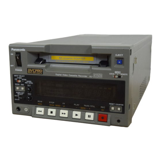
Summary of Contents for Panasonic AJ-D250P
-
Page 1: Operating Instructions
Printed in Japan VQT8188-2 Digital Video Cassette Recorder Operating Instructions EJ EC T ME NU LO CA L RE MO TE RE C IN RE MO TE CH 1 -30 -25 W ID E -20 -16 -12 -8 CH 2 CH 2 CT L SE RV O... - Page 2 IMPORTANT “Unauthorized recording television programs, video tapes and other materials may infringe the right of copyright owners and be contrary to copyright laws.” CAUTION RISK OF ELECTRIC SHOCK DO NOT OPEN CAUTION: TO REDUCE THE RISK OF ELECTRIC SHOCK, DO NOT REMOVE COVER (OR BACK). NO USER SERVICEABLE PARTS INSIDE.
-
Page 3: Table Of Contents
Contents Introduction ..... . . 4 Features ......4 Parts and Their Functions . -
Page 4: Introduction
Introduction The AJ-D250 is a digital VTR which uses 1/4˝ wide tapes. The incorporation of digital compression technology ensures that the deterioration in picture and sound quality suffered during dubbing will be much less than with conventional analog systems. The model has a compact and lightweight design, enabling it to be readily carried about or easily installed in a rack. -
Page 5: Parts And Their Functions
Parts and Their Functions Front panel CH 1 CH 2 POWER DIGITAL VIDEO CASSETTE INPUT SELECT S-VIDEO LINE OPTION AUDIO REC LEVEL CH 1 BEGIN END AUDIO OUT CH 2 SELECT CH 3 CH 4 Counter display 5 6 7 8 REC INH REMOTE WIDE... - Page 6 Parts and Their Functions Front panel 1 POWER switch When the ON side is pressed, power is supplied to the unit, and the counter display is illuminated. 2 Cassette insertion slot News gathering cassettes, cassettes consumer-use accompanied by the adapter are inserted into this slot.
- Page 7 UB: Set here to display the user’s bit. Remaining tape: Set here to display the amount of remaining tape. O RESET button When this button is pressed in the CTL mode, the counter display is reset to 00:00:00:00. When it is Panasonic (AG-A11)
-
Page 8: Connector Panel
Parts and Their Functions Connector panel INPUT S-VIDEO OUTPUT S-VIDEO 232C AUDIO 1 > VIDEO VIDEO AUDIO VIDEO VIDEO MONIT AUDIO 2 < AC IN SIGNAL... - Page 9 Parts and Their Functions Connector panel 1 AC IN socket Plug one end of the unit’s power cord into this power socket. 2 SIGNAL GND terminal In order to reduce noise, connect this terminal to the signal grounding terminal on one of the devices to which the unit is connected.
-
Page 10: Tapes
Long-playing tapes (80 min. in standard mode, 120 min. in LP mode) cannot be used with this unit. It is recommended that Panasonic brand consumer-use DV tapes be used. Remember that inserting a cassette tape without using the cassette adapter can cause malfunctioning. -
Page 11: Operation
Operation Turning on the power/inserting a cassette Before proceeding to operate the unit, make sure that the unit has been connected properly. Turn on the unit’s power. Insert the cassette tape. Insert it at the prescribed position without forcing it in any way. Check that the STOP lamp is lighted. -
Page 12: Stop Mode
Operation STOP mode When the STOP button is pressed, the STOP mode is established. The STOP lamp lights, and the tape stops traveling. O In order to protect the tape, the tape protection mode will be established when the time selected for the “STILL TIMER”... -
Page 13: Recording
Operation Recording Set the accidental erasure prevention tab on the cassette tape to “recording,” and insert the tape. Press the STOP button to set the unit to the STOP mode. Check that the REC INH lamp has gone off. Selecting the video and audio input signals and adjusting the audio levels Selecting the video and audio input signals Adjusting the audio levels Press the PLAY button while holding down the REC button. -
Page 14: Pause/Recording (Frame-To-Frame Continuity)
Operation Pause/record (frame-to-frame continuity) Press the PAUSE/STILL button while the cassette tape is playing. When ON has been selected as the AUTO BACK setup menu item setting, the tape will be rewound for about 2 seconds starting from the position where the PAUSE/STILL was pressed. -
Page 15: Frame By Frame Advance
Operation Frame by frame advance When the FF or REW button is pressed during still picture playback, the tape will be advanced forward or backward one frame at a time. O No sound will be heard during frame by frame advance. Audio switching The AUDIO OUT SELECT button is used to switch to the desired sound. -
Page 16: Repeat Playback
Operation Repeat playback Setting the BEGIN and END points [Menu mode] Set the unit to the menu mode (by setting the LOCAL/MENU/REMOTE switch to the MENU position). Select the “BGN PRESET” or “END PRESET” setup menu item, and press the DATA+ button (PAUSE/STILL button) or DATA–... - Page 17 Operation Setting the BEGIN and END points [Front panel] Set the unit to the local mode (by setting the LOCAL/MENU/REMOTE switch to the LOCAL position). When the BEGIN or END button on the front panel is pressed, the current position is set as the BEGIN or END point.
-
Page 18: Time Codes And User's Bit
Time Codes and User’s Bit Time codes Time codes are used when recording time code signals generated by the time code generator on the tape, reading out their values with the time code reader, and displaying the absolute positions of the tape in increments of hours, minutes, seconds and frames. The time codes are written in the sub-code area (data area) of the helical track. -
Page 19: Setting The Time Code
Time Codes and User’s Bit Setting the time code Set the unit to the menu mode (by setting the LOCAL/MENU/REMOTE switch to the MENU position). Select the “TC PRESET” setup menu item, and press the DATA+ button (PAUSE/STILL button) or DATA– button (PLAY button). (See page 32) Select the digit to be changed (blinking display) using the UP button (FF button) or DOWN button (STOP button). -
Page 20: Playing Back The Time Code/User's Bit
Time Codes and User’s Bit Playing back the time code/user’s bit Set the unit to the STOP mode. Set to TC or UB using the COUNTER button. TC: The time code appears on the display. UB: The user’s bit appears on the display. O Interpolation is provided by the CTL signal if the time code cannot be read. -
Page 21: Superimposed Screens
Superimposed Screens When the unit’s MONITOR OUT connector has been connected to a TV monitor, the control signals, time codes, etc. are displayed on the TV monitor screen as abbreviations. The display can be switched ON or OFF using the setup menu item No. - Page 22 Superimpose Screens Operation mode The value to be displayed can be selected using setup menu item No.001 “DISPLAY SEL”. (See page 28) TIME: Counter value T&STA: Counter value and VTR operation mode T&R: Counter value and remaining tape amount T&S&R: Counter value, VTR operation mode and remaining tape amount TIME mode Counter value...
-
Page 23: Setup (Initial Settings)
Setup (Initial Settings) The unit’s main settings can be performed and checked using the on-screen menus which appear on the video monitor connected to the unit. It is also possible to perform and check the settings using the item numbers and setting numbers which appear on the front panel’s display. -
Page 24: How To Set The User Default Settings
Setup (Initial Settings) Press the MENU-UP button or MENU-DOWN button to position the cursor at LOAD, and press the SET button. The unit is set to the LOAD mode, and the LOAD screen appears on the video monitor. SET–UP MENU <LOAD>... -
Page 25: How To Load The User Default Settings
Setup (Initial Settings) How to load the user default settings Set the LOCAL/MENU/REMOTE switch to the MENU position. The unit is now set to the menu setting mode, and the menu screen appears on the video monitor. Press the RESET button. The unit is set to the default setting mode, and the default setting screen appears on the video monitor. -
Page 26: How To Release The Menu Protect Mode
Setup (Initial Settings) Set the LOCAL/MENU/REMOTE switch to the LOCAL or REMOTE position. The unit is now set to the menu protect mode. When the LOCAL/MENU/REMOTE switch is set to the MENU position, “MENU PROTECTED” appears on the video monitor screen instead of the menu setting mode being established. -
Page 27: Setup Menus
Setup Menus SYSTEM menu Item Superimposed display SYSTEM H 0000 0255 SC COARSE 0000 0001 0002 0003 SC FINE 0000 0255 SCH COARSE 0000 0001 0002 0003 SCH FINE 0000 0255 VIDEO LEVEL 0000 0128 0255 SET UP LEVEL 0000 0128 0255 0000... -
Page 28: Basic Menu
Setup Menus BASIC menu Item Superimposed display SUPER 0000 0001 DISPLAY SEL 0000 0001 0002 0003 CHARA H-POS 0000 0001 0003 0007 CHARA V-POS 0000 0001 0003 0007 CHARA TYPE 0000 0001 The underlining denotes the factory mode setting. <Note> If the DATA+ button or DATA–... -
Page 29: Operation Menu
Setup Menus OPERATION menu Item Superimposed display LOCAL ENABLE 0000 0001 TAPE TIMER 0000 0001 S/F/R EE SEL 0000 0001 WIDE MODE 0000 0001 0002 TAPE IN MOD 0000 0001 0002 0003 TAPE END MOD 0000 0001 0002 0003 AUTO BACK 0000 0001 FORMAT SEL... -
Page 30: Interface Menu
Setup Menus INTERFACE menu Item Superimposed display BAUD RATE 0000 0001 0002 0003 0004 DATA LENGTH 0000 0001 STOP BIT 0000 0001 PARITY 0000 0001 0002 ACK RETURN 0000 0001 232C ID SEL 0000 0001 The underlining denotes the factory mode setting. Setting Superimposed display... -
Page 31: Tape Protect Menu
Setup Menus TAPE PROTECT menu Item Superimposed display STILL TIMER 0000 0001 0002 0003 0004 0005 SRC PROTECT 0000 0001 DRUM STDBY 0000 0001 STOP PROTECT 0000 0001 The underlining denotes the factory mode setting. <Note> When a consumer-use DV format tape is used, the tape protection mode will be established in 10 seconds even if 30s, 1min or 2min is selected as the STILL TIMER item setting. -
Page 32: Time Code Menu
Setup Menus TIME CODE menu Item Superimposed display VITC POS-1 0000 0001 0006 0010 VITC POS-2 0000 0001 0008 0010 VITC BLANK 0000 0001 TCG REGEN 0000 0001 0002 BINARY GP 0000 0001 0002 0003 0004 0005 0006 0007 DF MODE 0000 0001 TC MODE... -
Page 33: Video Menu
Setup Menus VIDEO menu Item Superimposed display VIDEO MODE 0000 0001 V-MUTE SEL 0000 0001 CC (F1) BLANK 0000 0001 CC (F2) BLANK 0000 0001 FREEZE SEL 0000 0001 IN FRM DET 0000 0001 STD/NSTD SEL 0000 0001 VIN SETUP 0000 0001 VOUT SETUP... -
Page 34: Audio Menu
Setup Menus AUDIO menu Item Superimposed display AUDIO EDIT IN 0000 0001 AUDIO EDIT OUT 0000 0001 PB FADE 0000 0001 0002 SEARCH CUE 0000 0001 DV PB ATT 0000 0001 CUE INSERT 0000 0001 The underlining denotes the factory mode setting. Setting Superimposed display... -
Page 35: Editing
Editing Editing with the RS-232C remote control Using the RS-232C remote control (AJ-A250), which is available as an optional accessory, two units—a player VTR and a recorder VTR—can be controlled directly from the controller to enable speedier and more efficient assemble editing, insert editing and other editing jobs. Preparation: O As shown in the figure below, connect the player VTR and recorder VTR to the RS-232C remote control. -
Page 36: Audio Editing Functions
Audio editing functions The information (setup menu item No. 700, 701) concerning the selection of the joining method used at the edit points is recorded during digital audio editing, and this information is detected during playback so that the edit points can be processed automatically. This applies only when AUTO has been selected as the playback fade selection (setup menu item No.702) setting. -
Page 37: First Edit Function
First Edit Function The CTL (control) signal must be recorded ahead of time onto the editing tape. The method used to record it differs depending on whether assemble editing or insert editing is to be performed. First edit for assemble editing In the case of a tape for assemble editing, the CTL signal is recorded at the beginning of where the recording is to be commenced. -
Page 38: Rs-232C
RS-232C The following functions can be controlled using the RS-232C interface. $ Basic operations EJECT INSERT STOP SEARCH PAUSE PLAY SEARCH SPEED UP REC/PLAY SEARCH SPEED DOWN FORWARD/ADVANCE REVERSE/ADVANCE PAUSE REVERSE/PLAY COUNTER RESET DIRECT SEARCH $ Status checks The current VTR mode can be checked. $ Simple editing functions Video/audio, audio/video and various other insert editing operations can be performed. -
Page 39: Software Specifications
RS-232C 2. Software specifications (1) External interface specifications Communication Asynchronous system, full duplex system Baud rate 1200, 2400, 4800, 9600 or 19200 bps Bit length 8 bits or 7 bits Stop bit 1 bit or 2 bits Parity None, odd or even <Notes>... -
Page 40: Receiving Format (Vtr Computer)
RS-232C (3) Receiving format (VTR The VTR responds to a send command with the format data below. 1. First, the VTR returns the data indicating whether the command from the computer was received properly. 1) If the communication was error-free, the VTR returns the ACK (Acknowledge) data. -
Page 41: Command List
RS-232C (4) Command list $ List of commands The table below lists the send commands and operations for each mode as seen from the computer end. [STX] = HEX code 02H [ETX] = HEX code 03H = HEX code 3AH The discrimination part and data part represent the ASCII codes which support the corresponding symbols. - Page 42 RS-232C O Display control commands Sends data of computer [STX] DFC:m [ETX] O Edit control commands Sends data of computer [STX] EAB:m [ETX] [STX] EAD:m [ETX] [STX] EIN [ETX] [STX] EFE:data [ETX] O Media operation control commands Sends data of computer [STX] HRE:m [ETX] [STX] HTE:m [ETX] [STX] HTI:m [ETX]...
- Page 43 RS-232C O Operation control commands Sends data of computer [STX] OAF [ETX] [STX] OAR [ETX] [STX] OBF [ETX] [STX] OBN [ETX] [STX] OEJ [ETX] [STX] OFF [ETX] [STX] OPA [ETX] [STX] OPL [ETX] [STX] OPR [ETX] [STX] OPT:data [ETX] [STX] ORC [ETX] [STX] ORP [ETX] [STX] ORW [ETX] [STX] OSD [ETX]...
- Page 44 RS-232C O Query control commands Sends data of computer [STX] QAL [ETX] [STX] QAO [ETX] [STX] QCA [ETX] [STX] QCB [ETX] [STX] QCC [ETX] [STX] QCD [ETX] [STX] QCE [ETX] [STX] QCF [ETX] [STX] QCM [ETX] [STX] QCP [ETX] [STX] QCR [ETX] [STX] QCS [ETX] [STX] QCT [ETX] [STX] QCU [ETX]...
- Page 45 RS-232C O Query control commands Sends data of computer [STX] QLH:m [ETX] [STX] QOT [ETX] [STX] QOP [ETX] [STX] QOD:d1d2 [ETX] [STX] QOS [ETX] [STX] QRA [ETX] [STX] QRS [ETX] [STX] QRV:m [ETX] [STX] QSM [ETX] [STX] QSY [ETX] [STX] QSP:m [ETX] [STX] QTT [ETX] [STX] QVI [ETX] [STX] QVM [ETX]...
- Page 46 RS-232C O Searches control commands Sends data of computer [STX] SCP:data [ETX] [STX] SCS:data [ETX] [STX] SMI:data [ETX] [STX] SMM:m [ETX] [STX] SMP:data [ETX] [STX] SMS [ETX] [STX] SPT:data [ETX] [STX] SRS:data [ETX] [STX] SUB:data [ETX] O Timer control commands Sends data of computer [STX] TST:data [ETX] Return data from VTR...
- Page 47 RS-232C $ Audio control commands Sends data of computer [STX] AOC:m [ETX] Parameters m = 1: CH1 2: CH2 3: CH3 4: CH4 5: CH1 & CH2 6: CH3 & CH4 7: CH1+3 & CH2+4 $ Counter control commands Sends data of computer [STX] CCP:data [ETX] Parameters data = ghmmssff...
- Page 48 RS-232C $ Counter control commands Sends data of computer [STX] CLP:data [ETX] Parameters data = ghmmssff g = Blank: With a positive value – sign: With a negative value 0 9: Hours mm = 00 59: Minutes ss = 00 59: Seconds ff = 00 29: Frames [STX] CRN:m [ETX]...
- Page 49 RS-232C $ Counter control commands Sends data of computer [STX] CTP [ETX] [STX] CTR [ETX] [STX] CTS:data [ETX] Parameters data = hhmmssff hh = 00 23: Hours mm = 00 59: Minutes ss = 00 59: Seconds ff = 00 29: Frames [STX] CUS:data [ETX] Parameters data = U...
- Page 50 RS-232C $ Edit control commands Sends data of computer [STX] EAB:m [ETX] Parameters m = N: AUTO BACK ON F: AUTO BACK OFF [STX] EAD:m [ETX] Parameters m = 0: CH1 & CH2 1: CH1 2: CH2 No parameter: CH1 & CH2 [STX] EIN [ETX] [STX] EFE:data [ETX] Parameters...
- Page 51 RS-232C $ Media operation control commands Sends data of computer [STX] HRE:m [ETX] Parameters m = S: STOP R: REWIND E: EJECT M: REWIND and EJECT [STX] HTE:m [ETX] Parameters m = S: STOP R: REWIND E: EJECT M: REWIND and EJECT [STX] HTI:m [ETX] Parameters m = S: STOP...
- Page 52 RS-232C $ Operation control commands Sends data of computer [STX] OAF [ETX] [STX] OAR [ETX] [STX] OBF [ETX] [STX] OBN [ETX] [STX] OEJ [ETX] [STX] OFF [ETX] [STX] OPA [ETX] [STX] OPL [ETX] [STX] OPR [ETX] [STX] OPT:data [ETX] Parameters data = wghmmssff O When the CTL data is to be used as the reference...
- Page 53 RS-232C $ Operation control commands Sends data of computer [STX] OSD [ETX] [STX] OSF:n [ETX] Parameters O In the case of a DVCPRO format tape n = 0: STILL 6: a1.85 1: a0.03 7: a4.1 2: a0.1 8: a9.5 3: a0.3 9: a16.0 4: a0.43 A: a32.0...
- Page 54 RS-232C $ Operation control commands Sends data of computer [STX] OSR:n [ETX] Parameters O In the case of a DVCPRO format tape n = 0: STILL 6: a1.85 1: a0.03 7: a4.1 2: a0.1 8: a9.5 3: a0.3 9: a16.0 4: a0.43 A: a32.0 5: a1...
- Page 55 RS-232C $ Query control commands Sends data of computer [STX] QAL [ETX] [STX] QAO [ETX] m = 1: CH1 [STX] QCA [ETX] data = U [STX] QCB [ETX] data = U [STX] QCC [ETX] data = ghmmss O In the case of CTL data g = Blank: With a positive value mm = 00 ss = 00...
- Page 56 RS-232C $ Query control commands Sends data of computer [STX] QCE [ETX] data = hhmmssff hh = 00 mm = 00 ss = 00 ff = [STX] QCF [ETX] m = N: Drop frame mode [STX] QCM [ETX] m = 1: 12-hour mode [STX] QCP [ETX] data = ppqq pp = Insertion line 1...
- Page 57 RS-232C $ Query control commands Sends data of computer [STX] QEB [ETX] m = N: AUTO BACK ON [STX] QHC [ETX] data = C = I: Cassette in = E: Recording enabled = S: S size cassette = D: DV format [STX] QHE [ETX] m = S: STOP [STX] QHI [ETX]...
- Page 58 RS-232C $ Query control commands Sends data of computer [STX] QIE [ETX] data = m1m2 m1 = 0 m2 = 0 Parameter Bits supported BIT7 Switching data [STX] QLH:m [ETX] Parameters data = mhhhhh m = D: Cumulative drum rotation m = D: Drum time hhhhh = 00000...
- Page 59 RS-232C $ Query control commands Sends data of computer [STX] QOP [ETX] data = OSP: STOP OEJ: EJECT OFF: FAST FORWARD ORW: REWIND OSF: SHUTTLE FORWARD OSR: SHUTTLE REVERSE OSS: STILL OPL: PLAY OPP: PLAY PAUSE ORC: REC ORP: REC PAUSE OBF: STANDBY OFF SCS: COUNTER SEARCH (STILL) SCP: COUNTER SEARCH (PLAY)
- Page 60 RS-232C O Bitmap table (A) ADDRESS BIT7 BIT6 AD 0 AD 1 STANDBY AD 2 SERVO LOCK AD 3 AD 4 SELECT EE FULL EE AD 5 INSERT AD 6 LAMP STILL AD 7 AD 8 AD 9 AD A AD B AD C AD D...
- Page 61 RS-232C $ Query control commands Sends data of computer [STX] QOS [ETX] data = AD <Note> Refer to the bitmap table (B) for details of AD [STX] QRA [ETX] m = N: ACK ON [STX] QRS [ETX] m = 0: Normal [STX] QRV:m [ETX] Parameters data = d1d2.d3d4-d5d6-d7.d8d9...
- Page 62 RS-232C O Bitmap table (B) ADDRESS BIT7 BIT6 AD 0 FULL EE SELECT EE AD 1 SHORT PLAY REC INHIBIT CASSETTE AD 2 IN/OUT TAPE AD 3 DIRECTION INSERT AD 4 VIDEO <Note > “1” is used as the TAPE END bit and TAPE TOP bit when the tape start or end is detected, and the bits are cleared to “0”...
- Page 63 RS-232C $ Query control commands Sends data of computer [STX] QSP:m [ETX] Parameters data = pw:ghmmssff O When CTL data is to be used as B: BEGIN point the reference E: END point pw = BP: BEGIN point mm = 00 ss = 00 ff = O When TC data is to be used as the...
- Page 64 RS-232C $ Communication control commands Sends data of computer [STX] RAN [ETX] [STX] RAF [ETX] [STX] RCK [ETX] [STX] RSE:m [ETX] Parameters 0: Normal 1: No completion command 2: No completion command/No error Return data from VTR [STX] RAN [ETX] Enables the return of the ACK (Acknowledge) code.
- Page 65 RS-232C $ Search control commands Sends data of computer [STX] SCP:data [ETX] Parameters data = ghmmssff O When CTL data is to be used as the reference g = Blank: With a positive value – sign: With a negative value Hours mm = 00 59: Minutes...
- Page 66 RS-232C $ Search control commands Sends data of computer [STX] SMI:data [ETX] Parameters data = wwghmmssff O When the counter value is to be stored in the memory ww = LC: CTL data reference SC: TC data reference “ghmmssff” is omitted. O When the parameter value for which the CTL data serves as the reference is to be stored in...
- Page 67 RS-232C $ Search control commands Sends data of computer [STX] SMP:data [ETX] Parameters data = pww:ghmmssff O When the counter value is to be stored in the memory B: BEGIN point E: END point ww = LC: CTL data reference SC: TC data reference “ghmmssff”...
- Page 68 RS-232C $ Search control commands Sends data of computer [STX] SMS [ETX] [STX] SPT:data [ETX] Parameters data = ghmmssff O When CTL data is to be used as the reference g = Blank: With a positive value – sign: With a negative value Hours mm = 00 59: Minutes...
- Page 69 RS-232C $ Search control commands Sends data of computer [STX] SRS:data [ETX] Parameters data = wghmmssff O When CTL data is to be used as the reference w = L: CTL data reference g = Blank: With a positive value –...
- Page 70 RS-232C $ Timer control commands Sends data of computer [STX] TST:data [ETX] Parameters data = mmmm mmmm = 0000: 0.5 sec. 0005: 5 sec. 0010: 10 sec. 0030: 30 sec. 0100: 1 min. 0200: 2 min. Return data from VTR [STX] TST [ETX] Sets the standby OFF timer.
- Page 71 RS-232C $ Mode transition table Return STANDBY command STOP EJECT ± ± ± ± ± ± ± ± ± ± ± ± ± ± ± ± ± ± ± ± ± ± ± ± ± Search ± ± commands <Notes> ±...
- Page 72 RS-232C $ Mode transition table Return VIDEO VIDEO command STILL INSERT INSERT PAUSE ± ± ± ± ± ± PLAY VIDEO PLAY PAUSE INSERT ± ± ± A/V INSERT ± PAUSE ± ± ± ± ± Search ± commands <Notes> ±...
-
Page 73: Checkpoints For Rs-232C Communication
RS-232C (5) Checkpoints for RS-232C communication $ Send commands and data returned from the 1. If the LOCAL/MENU/REMOTE switch on the front panel is not at the REMOTE position, it is not possible to exercise proper control using the RS-232C interface. If any command except a Q (query) command is sent while this switch is not at the REMOTE position, error code ER001 is returned. -
Page 74: Error Messages
Error Messages When a problem has occurred in the unit, one of the following error messages will appear on the tape counter. Error No. Description — d — Condensation (dew) has formed. Appears when the servo fails to lock for 3 or more seconds. -
Page 75: Emergency Eject
Emergency Eject Procedure for removing the tape manually in an emergency Use the procedure below to remove the cassette tape if it can not be removed even when the EJECT button is pressed. O Before proceeding to eject the tape manually, you must first turn off the power to the unit. 1 Remove the top panel. -
Page 76: Video Head Cleaning
Video Head Cleaning This unit is equipped with an auto head cleaning function which automatically reduces the amount of dirt on the video heads. However, in order to maximize the unit’s reliability, it is recommended that the video heads be cleaned as and when appropriate. For further details on how to actually clean the heads, consult with one of our service companies or with your dealer. -
Page 77: Specifications
Specifications [GENERAL] Supply voltage: 120 V AC, 50 – 60 Hz Power consumption: 56 W Ambient operating temperature: 41°F to 104°F (5°C to 40°C) Ambient operating humidity: 35% to 80% (no condensation) Weight: 14.3 lb (6.5 kg) Dimensions (WaHaD): ˝a5 ˝a15 ˝... - Page 78 Specifications [AUDIO] $ Digital audio Sampling frequency: 48 kHz Quantizing: 16 bits Frequency response: 20 Hz to 20 kHz (0 +1.0 dB, –2.0 dB) Dynamic range: More than 85 dB (1 kHz, emphasis OFF, “A” weighted) Distortion: Less than 0.1% (1 kHz, emphasis OFF, reference level) Crosstalk: Less than –80 dB (1 kHz, between 2 channels)
- Page 80 DIVISION OF MATSUSHITA ELECTRIC CORPORATION OF AMERICA Executive Office: 3330 Cahuenga Blvd W., Los Angeles, CA 90068 (323) 436-3500 EASTERN ZONE: One Panasonic Way 4E-7, Secaucus, NJ 07094 (201) 348-7621 Mid-Atlantic/New England: One Panasonic Way 4E-7, Secaucus, NJ 07094 (201) 348-7621 Southeast Region:...