Table of Contents
Advertisement
Quick Links
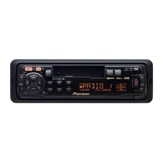
MULTI-CD CONTROL HIGH POWER CASSETTE PLAYER WITH RDS TUNER
KEH-P1010R
KEH-P1013R
CONTENTS
6.ADJUSTMENT
PIONEER CORPORATION
PIONEER ELECTRONICS SERVICE INC.
PIONEER EUROPE NV
Haven 1087 Keetberglaan 1, 9120 Melsele, Belgium
PIONEER ELECTRONICS ASIACENTRE PTE.LTD. 253 Alexandra Road, #04-01, Singapore 159936
PIONEER CORPORATION 2000
KEH-P1010R/XM/EW
2
2
8
14
21
25
4-1, Meguro 1-Chome, Meguro-ku, Tokyo 153-8654, Japan
P.O.Box 1760, Long Beach, CA 90801-1760 U.S.A.
/
XM
EW
7.2.1 IC
K-ZZS. NOV. 2000 Printed in Japan
ORDER NO
CRT2607
XM/EW
26
26
26
27
28
28
32
33
34
Advertisement
Table of Contents

Related Manuals for Pioneer KEH-P1010R


Summary of Contents for Pioneer KEH-P1010R
- Page 1 PIONEER ELECTRONICS SERVICE INC. P.O.Box 1760, Long Beach, CA 90801-1760 U.S.A. PIONEER EUROPE NV Haven 1087 Keetberglaan 1, 9120 Melsele, Belgium PIONEER ELECTRONICS ASIACENTRE PTE.LTD. 253 Alexandra Road, #04-01, Singapore 159936 PIONEER CORPORATION 2000 K-ZZS. NOV. 2000 Printed in Japan...
-
Page 2: Safety Information
KEH-P1010R,P1013R 1. SAFETY INFORMATION CAUTION This service manual is intended for qualified service technicians; it is not meant for the casual do-it-yourselfer. Qualified technicians have the necessary test equipment and tools, and have been trained to properly and safely repair complex products such as those covered by this manual. - Page 3 KEH-P1010R,P1013R NOTE Parts marked by “*” are generally unavailable because they are not in our Master Spare Parts List. PACKING SECTION PARTS LIST KEH-P1010R/XM/EW Mark No. Description Part No. Mark No. Description Part No. 1 Carton CZH5577 11 Owner’s Manual CZR2942 2 Owner’s Manual...
- Page 4 KEH-P1010R,P1013R 2.2 EXTERIOR...
- Page 5 33 Door See Contrast table(2) 34 Arm CNV4728 35 Spring CBH1835 (2)CONTRAST TABLE KEH-P1010R/XM/EW and KEH-P1013R/XM/EW have the same construction except for the following: Part No. Symbol and Description Mark No. KEH-P1010R/XM/EW KEH-P1013R/XM/EW C Z X 5 5 1 3...
- Page 6 KEH-P1010R,P1013R 2.3 CASSETTE MECHANISM...
- Page 7 KEH-P1010R,P1013R NOTE For the cassette mechanism, only the parts listde here are available as spare parts. The others (not shown in the list)cannot be supplied. CASSETTE MECHANISM SECTION PARTS LIST Mark No. Description Part No. 1 Washer 1-0036-5024 2 Roller...
- Page 8 KEH-P1010R,P1013R 3. BLOCK DIAGRAM AND SCHEMATIC DIAGRAM 3.1 BLOCK DIAGRAM...
- Page 9 KEH-P1010R,P1013R...
- Page 10 KEH-P1010R,P1013R 3.2 OVERALL CONNECTION DIAGRAM...
- Page 11 KEH-P1010R,P1013R...
-
Page 12: Keyboard Unit
KEH-P1010R,P1013R 3.3 KEYBOARD UNIT... - Page 13 KEH-P1010R,P1013R 3.4 CASSETTE MECHANISM...
-
Page 14: Pcb Connection Diagram
KEH-P1010R,P1013R 4. PCB CONNECTION DIAGRAM 4.1 TUNER AMP UNIT NOTE FOR PCB DIAGRAMS 1. The parts mounted on this PCB include all necessary parts for several destination. For further information for respective destinations, be sure to check with the schematic diagram. - Page 15 KEH-P1010R,P1013R SIDE A...
- Page 16 KEH-P1010R,P1013R TUNER AMP UNIT...
- Page 17 KEH-P1010R,P1013R SIDE B...
- Page 18 KEH-P1010R,P1013R 4.2 KEYBOARD UNIT...
- Page 19 KEH-P1010R,P1013R SIDE A SIDE B...
- Page 20 KEH-P1010R,P1013R 4.3 CASSETTE MECHANISM...
-
Page 21: Electrical Parts List
KEH-P1010R,P1013R 5. ELECTRICAL PARTS LIST NOTES: Parts whose parts numbers are omitted are subject to being not supplied. The part numbers shown below indicate chip components. Chip Resistor RS1/_S___J,RS1/__S___J Chip Capacitor (except for CQS..) CKS.., CCS.., CSZS..=====Circuit Symbol and No.===Part Name Part No. - Page 22 KEH-P1010R,P1013R =====Circuit Symbol and No.===Part Name Part No. =====Circuit Symbol and No.===Part Name Part No. ------ ------------------------------------------ ------------------------- ------ ------------------------------------------ ------------------------- Inductor LAU100K RS1/16S224J Terminal CKF1059 RD1/4PU162J Ceramic Resonator 6.29MHz CSS1310 RD1/4PU162J RS1/16S272J Crystal Resonator 3.648MHz CSS1447 JC 101 RS1/16S0R0J...
- Page 23 KEH-P1010R,P1013R =====Circuit Symbol and No.===Part Name Part No. =====Circuit Symbol and No.===Part Name Part No. ------ ------------------------------------------ ------------------------- ------ ------------------------------------------ ------------------------- RD1/4PU222J CKSRYB103K50 RD1/4PU222J CKSRYB472K50 RS1/16S821J CKSRYB473K25 RS1/16S821J CEAL101M10 RS1/16S473J CKSRYB182K50 RS1/16S473J CKSRYB223K25 RD1/4PU562J CKSRYB223K25 RS1/16S472J CKSRYB223K25 RS1/16S472J CKSRYB103K50 RS1/16S101J...
- Page 24 Motor Assy X-0363-7006 CEAL3R3M50 Head 1-0036-7123 CKSRYB473K25 CEALR10M50 CCSRCH101J50 CCSRCH101J50 CONTRAST TABLE of KEYBOARD UNIT KEH-P1010R/XM/EW and KEH-P1013R/XM/EW have the same construction except for the following: Part No. Symbol and Description KEH-P1013R/XM/EW KEH-P1010R/XM/EW CZE2950 CZE2951 PL 901 CZE2951 CZE2950 PL 902...
- Page 25 KEH-P1010R,P1013R 6. ADJUSTMENT There is no information to be shown in this chapter.
-
Page 26: General Information
KEH-P1010R,P1013R 7. GENERAL INFORMATION 7.1 DIAGNOSIS 7.1.1 DISASSEMBLY Removing the Upper Case(not shown) 1.Remove the Upper Case. Removing the Cassette Mechanism Module(Fig.1) Remove the four screws and then remove the Cassette Mechanism. Remove the Grille Assy(Fig.1) Remove the two screws. -
Page 27: Connector Function Description
KEH-P1010R,P1013R 7.1.2 CONNECTOR FUNCTION DESCRIPTION... -
Page 28: Parts
KEH-P1010R,P1013R 7.2 PARTS 7.2.1 IC BA4560F CA0008AM S-80834ANMP TB2118F TA8277H – – – – – – – – 10 11 12 13 14 15 16 17 18 19 20 21 22 23 24 25... - Page 29 KEH-P1010R,P1013R IC's marked by are MOS type. Be careful in handling them because they are very liable to be damaged by electrostatic induction PD6293A...
- Page 30 KEH-P1010R,P1013R Pin Functions(000874010) Pin No. Pin Name Format Function and Operation SD signal input FM stereo input ADPW A/D converter power supply control output AVSS MUTE System mute output Not used AVREF1 A/D converter reference voltage terminal KYDT Display data input...
- Page 31 KEH-P1010R,P1013R 000874010 - FM/AM Tuner Unit...
-
Page 32: Display
KEH-P1010R,P1013R 7.2.2 DISPLAY CZA5541... -
Page 33: Operational Flow Chart
KEH-P1010R,P1013R 7.3 OPERATIONAL FLOW CHART... -
Page 34: Operations And Specifications
KEH-P1010R,P1013R 8. OPERATIONS AND SPECIFICATIONS Key Finder Head Unit DISPLAY button buttons EJECT button SOURCE button Cassette door LOCAL/BSM button TA/AF button BAND button PTY button AUDIO button Detach button EQ button buttons Buttons 1–6 +/– buttons... - Page 35 KEH-P1010R,P1013R...
- Page 36 KEH-P1010R,P1013R...
- Page 37 KEH-P1010R,P1013R...
- Page 38 KEH-P1010R,P1013R Specifications General FM tuner Power source ..14.4 V DC (10.8 – 15.1 V allowable) Frequency range ........87.5 – 108 MHz Grounding system ........Negative type Usable sensitivity ............9 dBf (0.77 µV/75 Ω, mono, S/N: 30 dB) Max.