D-Link dxs-3350sr Installation & User Manual
Manages 10/100/1000mbps 48-port and 4 sfp combo ports with optional 2-port 10-gigabit layer 3 stackable ethernet switch
Hide thumbs
Also See for dxs-3350sr:
- Specifications (3 pages) ,
- User manual (392 pages) ,
- Command line interface reference manual (357 pages)

Related Manuals for D-Link dxs-3350sr


Summary of Contents for D-Link dxs-3350sr
- Page 1 D-Link ™ DXS-3350SR Managed 10/100/1000Mbps 48-port and 4 SFP Combo Ports with optional 2-Port 10-Gigabit Layer 3 Stackable Ethernet Switch Installation Guide and User Manual...
- Page 2 Microsoft Corporation. Other trademarks and trade names may be used in this document to refer to either the entities claiming the marks and names or their products. D-Link Computer Corporation disclaims any proprietary interest in trademarks and trade names other than its own.
-
Page 3: Table Of Contents
Switch To End Node ................................20 Switch to Hub or Switch ..............................21 Connecting To Network Backbone or Server........................22 Stacking and the DXS-3350SR ............................23 Stacking Limitations Utilizing a Ring or Star Toplogy ........................26 Stacking In a Star Topology ................................28 Introduction To Switch Management............................ - Page 4 Web-based Management Interface ............................. 30 SNMP-Based Management ..............................30 Command Line Console Interface Through the Serial Port ....................30 Connecting the Console Port (RS-232 DCE)............................. 30 First Time Connecting to the Switch..........................32 Password Protection ................................33 SNMP Settings ................................... 34 Traps........................................
- Page 5 Static Multicast Forwarding ............................... 73 VLANs....................................74 Understanding IEEE 802.1p Priority..........................74 VLAN Description ................................74 Notes About VLANs on the DXS-3350SR............................74 IEEE 802.1Q VLANs................................. 75 802.1Q VLAN Tags................................... 76 Port VLAN ID ....................................77 Tagging and Untagging ..................................78 Ingress Filtering....................................
- Page 6 Port Access Entity................................. 117 Port-Based Network Access Control ............................... 117 MAC-Based Network Access Control............................. 118 Configure Authenticator .................................. 119 Local Users...................................... 122 PAE System Control ................................ 123 Initialize Ports....................................124 Reauthenticate Port(s)..................................126 RADIUS Server................................127 Configuring Layer 3 IP Networking ............................. 128 L3 Global Advanced Settings ................................
- Page 7 DVMRP Interface Configuration..............................176 PIM_DM Interface Configuration ..............................178 Management..................................180 Security IP..................................181 User Accounts..................................181 Admin and User Privileges ................................182 Access Authentication Control ............................. 183 Policy & Parameters................................. 184 Application's Authentication Settings ..........................185 Authentication Server Group Settings..........................186 Authentication Server Hosts.............................
- Page 8 Save Changes ................................... 247 Reset....................................248 Reboot Device .................................. 249 Logout ......................................249 D-Link Single IP Management ............................. 250 Single IP Management (SIM) Overview..........................250 SIM Using The Web Interface ............................251 Topology Window ................................252 Tool Tips ......................................255...
- Page 9 Commander Switch Icon ................................. 257 Menu Bar..................................260 Device......................................261 View ........................................ 261 Firmware Upgrade (SIM)..............................262 Configuration File Backup/Restore (SIM) ........................262 Technical Specifications ............................... 263 Cables and Connectors................................265 Cable Lengths ..................................266 Glossary ....................................267...
-
Page 10: Preface
DXS-3350SR Gigabit Layer 3 Switch Preface The DXS-3350SR Manual is divided into sections that describe the system installation and operating instructions with examples. Section 1, Introduction - Describes the Switch and its features. Section 2, Installation - Helps you get started with the basic installation of the Switch and also describes the front panel, rear panel, side panels, and LED indicators of the Switch. -
Page 11: Intended Readers
DXS-3350SR Gigabit Layer 3 Switch Intended Readers The DXS-3350SR Manual contains information for setup and management of the Switch. This manual is intended for network managers familiar with network management concepts and terminology. Typographical Conventions Convention Description In a command line, square brackets indicate an optional entry. For example: [copy filename] means that optionally you can type copy followed by the name of the file. -
Page 12: Safety Instructions
DXS-3350SR Gigabit Layer 3 Switch Safety Instructions Use the following safety guidelines to ensure your own personal safety and to help protect your system from potential damage. Throughout this safety section, the caution icon ( ) is used to indicate cautions and precautions that you need to review and follow. -
Page 13: General Precautions For Rack-Mountable Products
DXS-3350SR Gigabit Layer 3 Switch • Observe extension cable and power strip ratings. Make sure that the total ampere rating of all products plugged into the extension cable or power strip does not exceed 80 percent of the ampere ratings limit for the extension cable or power strip. -
Page 14: Protecting Against Electrostatic Discharge
DXS-3350SR Gigabit Layer 3 Switch CAUTION: Never defeat the ground conductor or operate the equipment in the absence of a suitably installed ground conductor. Contact the appropriate electrical inspection authority or an electrician if you are uncertain that suitable grounding is available. -
Page 15: Introduction
DXS-3350SR Gigabit Layer 3 Switch Section 1 Introduction Gigabit Ethernet Switch Description Ports Front-Panel Components LED Indicators Side Panel Description Rear Panel Description Gigabit Combo Ports... -
Page 16: Gigabit Ethernet Technology
(45-48) and cannot be used simultaneously. Also included at the rear of the Switch are two 10-gigabit stacking ports used to stack up to 8 Switches. The DXS-3350SR may be used as a slave or master unit of a Switch stack when utilizing these two ports and can be configured in a Star or Ring topology, and in total, may provide a stacking solution of up to 384gigabit ports. -
Page 17: Features
DXS-3350SR Gigabit Layer 3 Switch Features • IEEE 802.3z compliant • IEEE 802.3x Flow Control in full-duplex compliant • IEEE 802.3u compliant • IEEE 802.3ab compliant • IEEE 802.3ae compliant (for optional XFP module) • IEEE 802.1p Priority Queues •... -
Page 18: Ports
DEM-310GT (1000BASE-LX), DEM- 311GT (1000BASE -SX), DEM-314GT (1000BASE -LH) and DEM-315GT (1000BASE -ZX) transceivers. See the figure below for installing the SFP ports in the Switch. Figure 1- 1. Inserting the fibe-optic transceivers into the DXS-3350SR... -
Page 19: Front-Panel Components
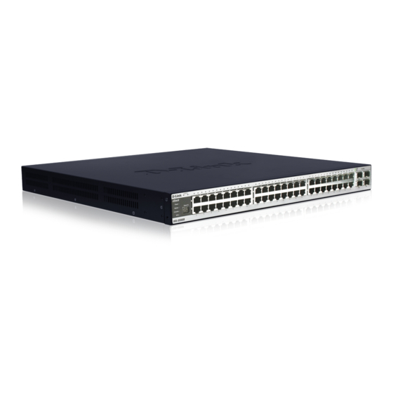
Switch. The front panel also includes a seven-segment LED indicating the Stack ID number, as well as 4 SFP ports, 48 1000BASE-T gigabit Ethernet ports. DXS-3350SR Figure 1- 2. Front Panel View of the DXS-3350SR as shipped Comprehensive LED indicators display the status of the Switch and the network. LED Indicators The Switch supports LED indicators for Power, Master, Console, RPS, SIO (stacking indicators) and Port LEDs. -
Page 20: Rear Panel Description
DXS-3350SR Gigabit Layer 3 Switch Rear Panel Description The rear panel of the Switch contains an AC power connector, an optional module slot for uplinking 2 XFP fibre-optic ports, 2 10-gigabit stacking ports, a redundant power supply connector, a RS-232 DCE console port for Switch management and a system fan. -
Page 21: Installation
DXS-3350SR Gigabit Layer 3 Switch SECTION 2 Installation Package Contents Before You Connect to the Network Installing the Switch Without the Rack Installing the Switch In a Rack The Optional Module External Redundant Power System... -
Page 22: Package Contents
• One Generic Quick Installation Guide If any item is found missing or damaged, please contact your local D-Link Reseller for replacement. Before You Connect to the Network The site where you install the Switch may greatly affect its performance. Please follow these guidelines for setting up the Switch. -
Page 23: Installing The Switch Without The Rack
DXS-3350SR Gigabit Layer 3 Switch Installing the Switch Without the Rack When installing the Switch on a desktop or shelf, the rubber feet included with the Switch should first be attached. Attach these cushioning feet on the bottom at each corner of the device. Allow enough ventilation space between the Switch and any other objects in the vicinity. -
Page 24: Mounting The Switch In A Standard 19" Rack
The Optional Module At the rear of the DXS-3350SR resides an optional module slot. This slot may be equipped with a 2-port 10GE XFP Uplink Module, sold separately. Adding the DEM-420X optional module will allow the administrator to add 2 fibre-optic ports which will transmit information at a rate of 10 gigabits a second. - Page 25 Optional Module Slot Figure 2- 4. Optional Module slot at the rear of the DXS-3350SR After removing the faceplate, remove the DEM-420X optional module from its box. The front panel should resemble the drawing represented in the following figure.
-
Page 26: External Redundant Power System
The Switch supports using the DPS-500 external redundant power system. DPS-500 documentation for more information. Figure 2- 8. The DXS-3350SR with the DPS-500 Redundant External Power Supply CAUTION: Do not use the Switch with any redundant power system other than the DPS-500. - Page 27 DXS-3350SR Gigabit Layer 3 Switch Figure 2- 9. The DXS-3350SR with the DPS-900 chassis and DPS-500 Redundant Power Supply...
-
Page 28: Connecting The Switch
DXS-3350SR Gigabit Layer 3 Switch Section 3 Connecting The Switch Switch To End Node Switch To Hub or Switch Connecting To Network Backbone or Server Stacking and the DXS-3350SR... -
Page 29: Switch To End Node
DXS-3350SR Gigabit Layer 3 Switch Switch To End Node End nodes include PCs outfitted with a 10, 100 or 1000 Mbps RJ 45 Ethernet/Fast Ethernet Network Interface Card (NIC) and most routers. An end node can be connected to the Switch via a twisted-pair UTP/STP cable. The end node should be connected to any of the 48 1000BASE-T ports of the Switch. -
Page 30: Switch To Hub Or Switch
DXS-3350SR Gigabit Layer 3 Switch Switch to Hub or Switch These connections can be accomplished in a number of ways using a normal cable. • A 10BASE-T hub or Switch can be connected to the Switch via a twisted-pair Category 3, 4 or 5 UTP/STP cable. -
Page 31: Connecting To Network Backbone Or Server
DXS-3350SR Gigabit Layer 3 Switch Connecting To Network Backbone or Server The 4 SFP ports and the 48 1000BASE-T ports are ideal for uplinking to a network backbone, server or server farm. The copper ports operate at a speed of 1000, 100 or 10Mbps in full or half duplex mode. The fiber optic ports can operate at 1000Mbps in full duplex mode only. -
Page 32: Stacking And The Dxs-3350Sr
Stacking and the DXS-3350SR The DXS-3350SR is equipped with 2 10-gigabit stacking ports at the rear of the Switch, as seen in the following figure. These stacking ports may be used to stack the DXS-3350SR to a master Switch to be used in a Switch stack. - Page 33 For stacking the in a ring architecture, both SIO ports will be in use, as shown in the following diagram. Up to eight DXS-3350SR Switches may be stacked together in the ring architecture Switch stack, though there are limitations on...
- Page 34 DXS-3350SR Gigabit Layer 3 Switch Figure 3- 8. Stacking in a Ring Architecture NOTICE: Do not connect the stacked Switch group to the network until you have properly configured all Switches for stacking. An improperly configured Switch stack can cause a broadcast storm.
-
Page 35: Stacking Limitations Utilizing A Ring Or Star Toplogy
DXS-3350SR Gigabit Layer 3 Switch Stacking Limitations Utilizing a Ring or Star Toplogy The Switches listed in the table below can all be stacked, but there is a limitation as to the number of Switches that can be included in a given stack. This limitation arises from a concept called a Token Cost. This Token Cost is used for communication between Switches in a Switch stack. - Page 36 For this example, a maximum of eight DXS-3350SR Switches (where none of these Switches have a 10G uplink) can be ring stacked. To determine how many DXS-3350SR Switches (each with a 10G uplink port) could be stacked in a ring stack, you need to redo the calculation above using a Token Cost of 6 for each DXS-3350SR Switch.
-
Page 37: Stacking In A Star Topology
So, in this case, you could add extra eight DGS-3324SR Switches to this ring stack. The entire stack would then consist of nine DGS-3324SR (Token Cost = 2), two DXS-3350SR (Token Cost = 4), three DXS-3326GSR (Token Cost = 2). This gives a total Token Cost for the stack of: 9 * 2 + 2 * 4 + 3 * 2 ≤... -
Page 38: Introduction To Switch Management
DXS-3350SR Gigabit Layer 3 Switch Section 4 Introduction To Switch Management Management Options Web-based Management Interface SNMP-Based Management Managing User Accounts Command Line Console Interface Through The Serial Port Connecting the Console Port (RS-232 DCE) First Time Connecting to The Switch... -
Page 39: Management Options
DXS-3350SR Gigabit Layer 3 Switch Management Options This system may be managed out-of-band through the console port on the front panel or in-band using Telnet. The user may also choose the web-based management, accessible through a web browser. Web-based Management Interface After you have successfully installed the Switch, you can configure the Switch, monitor the LED panel, and display statistics graphically using a web browser, such as Netscape Navigator (version 6.2 and higher) or Microsoft®... - Page 40 12. Enter the commands to complete your desired tasks. Many commands require administrator-level access privileges. Read the next section for more information on setting up user accounts. See the DXS-3350SR Command Line Interface Reference Manual on the documentation CD for a list of all commands and additional information on using the CLI.
-
Page 41: First Time Connecting To The Switch
Switch to refresh the console screen. Press Enter in both the Username and Password fields. You will be given access to the command prompt DXS-3350SR:4# shown below: There is no initial username or password. Leave the Username and Password fields blank. -
Page 42: Password Protection
Password Protection The DXS-3350SR does not have a default user name and password. One of the first tasks when settings up the Switch is to create user accounts. If you log in using a predefined administrator-level user name, you have privileged access to the Switch's management software. -
Page 43: Snmp Settings
The DXS-3350SR supports SNMP versions 1, 2c, and 3. You can specify which version of SNMP you want to use to monitor and control the Switch. The three versions of SNMP vary in the level of security provided between the management station and the network device. -
Page 44: Ip Address Assignment
DXS-3350SR Gigabit Layer 3 Switch IP Address Assignment Each Switch must be assigned its own IP Address, which is used for communication with an SNMP network manager or other TCP/IP application (for example BOOTP, TFTP). The Switch's default IP address is 10.90.90.90. You can change the default Switch IP address to meet the specification of your networking address scheme. -
Page 45: Connecting Devices To The Switch
DXS-3350SR Gigabit Layer 3 Switch Figure 4- 4. Assigning the Switch an IP Address In the above example, the Switch was assigned an IP address of 10.52.19.95 with a subnet mask of 255.0.0.0. The system message Success indicates that the command was executed successfully. The Switch can now be configured and managed via Telnet and the CLI or via the Web-based management. -
Page 46: Web-Based Switch Configuration
DXS-3350SR Gigabit Layer 3 Switch Section 5 Web-based Switch Configuration Introduction Login To Web manager Web-Based User Interface Basic Setup Reboot Basic Switch Setup Network Management Switch Utilities Network Monitoring IGMP Snooping Status... -
Page 47: Introduction
DXS-3350SR Gigabit Layer 3 Switch Introduction All software functions of the DXS-3350SR can be managed, configured and monitored via the embedded web-based (HTML) interface. The Switch can be managed from remote stations anywhere on the network through a standard browser such as Netscape Navigator/Communicator or Microsoft Internet Explorer. -
Page 48: Web-Based User Interface
DXS-3350SR Gigabit Layer 3 Switch Web-based User Interface The user interface provides access to various Switch configuration and management screens, allows you to view performance statistics, and permits you to graphically monitor the system status. Areas of the User Interface The figure below shows the user interface. -
Page 49: Web Pages
Area 1 Select the menu or window to be displayed. The folder icons can be opened to display the hyper- linked menu buttons and subfolders contained within them. Click the D-Link logo to go to the D- Link website. Area 2 Presents a graphical near real-time image of the front panel of the Switch. -
Page 50: Configuring The Switch
DXS-3350SR Gigabit Layer 3 Switch Section 6 Configuring The Switch Switch Information IP Address Advanced Settings Port Configuration Port Description Port Mirroring Link Aggregation LACP Port Setting MAC Notification IGMP Spanning Tree Forward Filtering VLANs Port Security System Log Servers... -
Page 51: Switch Information
DXS-3350SR Gigabit Layer 3 Switch Switch Information The subsections below describe how to change some of the basic settings for the Switch such as changing IP settings and assigning user names and passwords for management access privileges, as well as how to save the changes and restart the Switch. -
Page 52: Ip Address
The IP Address may initially be set using the console interface prior to connecting to it through the Ethernet. If the Switch IP address has not yet been changed, read the introduction of the DXS-3350SR Command Line Interface Manual or return to Section 4 of this manual for more information. - Page 53 DXS-3350SR Gigabit Layer 3 Switch The IP Address Settings options are: Parameter Description BOOTP The Switch will send out a BOOTP broadcast request when it is powered up. The BOOTP protocol allows IP addresses, network masks, and default gateways to be assigned by a central BOOTP server.
-
Page 54: Setting The Switch's Ip Address Using The Console Interface
DXS-3350SR Gigabit Layer 3 Switch Setting the Switch's IP Address using the Console Interface Each Switch must be assigned its own IP Address, which is used for communication with an SNMP network manager or other TCP/IP application (for example BOOTP, TFTP). The Switch's default IP address is 10.90.90.90. You can change the default Switch IP address to meet the specification of your networking address scheme. - Page 55 DXS-3350SR Gigabit Layer 3 Switch Parameter Description Serial Port Auto Select the logout time used for the console interface. This automatically logs the user Logout Time out after an idle period of time, as defined. Choose from the following options: 2 Minutes, 5 Minutes, 10 Minutes, 15 Minutes or Never.
-
Page 56: Box Informationconfiguration
DXS-3350SR Gigabit Layer 3 Switch Box InformationConfiguration The Box Information Configuration screen can be found in the Configuration folder under the heading Box Information. This window is used to configure the Master Switch of a Switch stack. The Master Switch is the Switch that will be used to configure the software applications regarding the Switch stack. -
Page 57: Port Configurations
DXS-3350SR Gigabit Layer 3 Switch Port Configurations This section contains information for configuring various attributes and properties for individual physical ports, including port speed and flow control. Clicking on Port Configurations in the Configuration menu will display the following window for the user: Figure 6- 5. - Page 58 DXS-3350SR Gigabit Layer 3 Switch To configure Switch ports: 1. Select the Switch with the port or ports you want to configure the in the Unit pull-down menu. 2. Choose the port or sequential range of ports using the From…To… port pull-down menus.
-
Page 59: Port Description
DXS-3350SR Gigabit Layer 3 Switch Port Description The DXS-3350SR supports a port description feature where the user may name various ports on the Switch. To assign names to various ports: 1. Click the Port Description on the Configuration menu. 2. Select the Unit in the stack you want to configure. -
Page 60: Port Mirroring
DXS-3350SR Gigabit Layer 3 Switch Port Mirroring The Switch allows you to copy frames transmitted and received on a port and redirect the copies to another port. You can attach a monitoring device to the mirrored port, such as a sniffer or an RMON probe, to view details about the packets passing through the first port. -
Page 61: Link Aggregation
Port trunk groups are used to combine a number of ports together to make a single high-bandwidth data pipeline. The DXS-3350SR supports up to 6 link aggreagation groups. The Switch treats all ports in a trunk group as a single port. Data transmitted to a specific host (destination address) will always be transmitted over the same port in a trunk group. - Page 62 DXS-3350SR Gigabit Layer 3 Switch Figure 6- 9. Link Aggregation Settings window – Add Figure 6- 10. Link Aggregation Group Configuration window – Modify...
- Page 63 DXS-3350SR Gigabit Layer 3 Switch The user-changeable Link Aggregation parameters are as follows: Parameter Description Group ID Select an ID number for the group, between 1 and 32. State Trunk groups can be toggled between Enabled and Disabled. This is used to turn a port trunking group on or off.
-
Page 64: Lacp Port Setting
DXS-3350SR Gigabit Layer 3 Switch LACP Port Setting The LACP Port Setting window is used in conjunction with the Link Aggregation window to create port trunking groups on the Switch. Using the following window, the user may set which ports will be active and passive in processing and sending LACP control frames. -
Page 65: Mac Notification
DXS-3350SR Gigabit Layer 3 Switch MAC Notification MAC Notification is used to monitor MAC addresses learned and entered into the forwarding database. MAC Notification Global Settings To globally set MAC notification on the Switch, open the following screen by opening the MAC Notification folder and clicking the MAC Notification Global Settings link: Figure 6- 12. -
Page 66: Mac Notification Port Settings
DXS-3350SR Gigabit Layer 3 Switch MAC Notification Port Settings To change MAC notification settings for a port or group of ports on the Switch, click Port Settings in the MAC Notification folder, which will display the following screen: Figure 6- 13. MAC Notification Port Settings and Port State Table... -
Page 67: Igmp
DXS-3350SR Gigabit Layer 3 Switch IGMP Internet Group Management Protocol (IGMP) snooping allows the Switch to recognize IGMP queries and reports sent between network stations or devices and an IGMP host. When enabled for IGMP snooping, the Switch can open or close a port to a specific device based on IGMP messages passing through the Switch. -
Page 68: Static Router Ports
DXS-3350SR Gigabit Layer 3 Switch The following parameters may be viewed or modified: Parameter Description VLAN ID This is the VLAN ID that, along with the VLAN Name, identifies the VLAN the user wishes to modify the IGMP Snooping Settings for. - Page 69 DXS-3350SR Gigabit Layer 3 Switch A router port will be dynamically configured when IGMP query packets, RIPv2 multicast, DVMRP multicast or PIM-DM multicast packets are detected flowing into a port. Open the IGMP folder and the click on the Static Router Ports Entry link to open the Current Static Router Ports Entries page, as shown below.
-
Page 70: Spanning Tree
802.1d STP will be familiar to most networking professionals. However, since 802.1w RSTP and 802.1s MSTP has been recently introduced to D-Link managed Ethernet Switches, a brief introduction to the technology is provided below followed by a description of how to set up 802.1d STP, 802.1w RSTP and 802.1s MSTP. -
Page 71: Port Transition States
DXS-3350SR Gigabit Layer 3 Switch Port Transition States An essential difference between the three protocols is in the way ports transition to a forwarding state and in the way this transition relates to the role of the port (forwarding or not forwarding) in the topology. MSTP and RSTP combine the transition states disabled, blocking and listening used in 802.1d and creates a single state Discarding. -
Page 72: Stp Bridge Global Settings
DXS-3350SR Gigabit Layer 3 Switch STP Bridge Global Settings To open the following window, open the Spanning Tree folder in the Configuration menu and click the STP Bridge Global Settings link. Figure 6- 18. STP Bridge Global Settings NOTE: The Hello Time cannot be longer than the Max. Age. Otherwise, a configuration error will occur. - Page 73 DXS-3350SR Gigabit Layer 3 Switch The following parameters can be set: Parameter Description STP Status Use the pull-down menu to enable or disable STP globally on the Switch. The default is Disabled. STP Version Use the pull-down menu to choose the desired version of STP to be implemented on the Switch.
-
Page 74: Mst Configuration
DXS-3350SR Gigabit Layer 3 Switch MST Configuration The following screens in the MST Configuration Table window allow the user to configure a MSTI instance on the Switch. These settings will uniquely identify a multiple spanning tree instance set on the Switch. The Switch initially possesses one CIST or Common Internal Spanning Tree of which the user may modify the parameters for but cannot change the MSTI ID for, and cannot be deleted. - Page 75 DXS-3350SR Gigabit Layer 3 Switch Figure 6- 20. Instance ID Settings window- Add The user may configure the following parameters to create a MSTI in the Switch. Parameter Description MSTI ID Enter a number between 1 and 15 to set a new MSTI on the Switch.
- Page 76 DXS-3350SR Gigabit Layer 3 Switch To configure the parameters for a previously set MSTI, click on its hyperlinked MSTI ID number, which will reveal the following screen for configuration. Figure 6- 22. Instance ID Settings window – modify The user may configure the following parameters for a MSTI on the Switch.
-
Page 77: Msti Port Settings
DXS-3350SR Gigabit Layer 3 Switch MSTI Port Settings This window displays the current MSTI configuration settings and can be used to update the port configuration for an MSTI ID. If a loop occurs, the MSTP function will use the port priority to select an interface to put into the forwarding state. Set a higher priority value for interfaces to be selected for forwarding first. -
Page 78: Stp Instance Settings
DXS-3350SR Gigabit Layer 3 Switch STP Instance Settings The following window displays MSTIs currently set on the Switch. To view the following table, click Configuration > Spanning Tree > STP Instance Settings: Figure 6- 25. STP Instance Settings To configure the Priority settings for an existing Instance Type entry, click on its hyperlinked name in the STP Instance Table, which will reveal the following window to configure: Figure 6- 26. -
Page 79: Stp Port Information
DXS-3350SR Gigabit Layer 3 Switch STP Port Information STP can be set up on a port per port basis. To view the following window click Configuration > Spanning Tree > MST Port Information: Figure 6- 27. STP Port Settings and MSTP Port Information Table... - Page 80 DXS-3350SR Gigabit Layer 3 Switch The following STP Port Settings can be configured: Parameter Description Unit Select the unit in the stack you want to configure. From/To <Port 1> A consecutive group of ports may be configured starting with the selected port.
-
Page 81: Forwarding Filtering
DXS-3350SR Gigabit Layer 3 Switch Forwarding Filtering Unicast Forwarding Open the Forwarding Filtering folder in the Configuration menu and click on the Unicast Forwarding link. This will open the Setup Static Unicast Forwarding Table, as shown below: Figure 6- 28. Setup Static Unicast Forwarding Table and current Static Unicast Forwarding Table... -
Page 82: Static Multicast Forwarding
DXS-3350SR Gigabit Layer 3 Switch Static Multicast Forwarding The following figure and table describe how to set up Multicast Forwarding on the Switch. Open the Forwarding Filtering folder and click on the Multicast Forwarding link to see the entry screen below: Figure 6- 29. -
Page 83: Vlans
VLANs without a network device performing a routing function between the VLANs. • The DXS-3350SR supports IEEE 802.1Q VLANs and Port-Based VLANs. The port untagging function can be used to remove the 802.1Q tag from packet headers to maintain compatibility with devices that are tag-unaware. -
Page 84: Ieee 802.1Q Vlans
DXS-3350SR Gigabit Layer 3 Switch IEEE 802.1Q VLANs Some relevant terms: Tagging - The act of putting 802.1Q VLAN information into the header of a packet. Untagging - The act of stripping 802.1Q VLAN information out of the packet header. -
Page 85: 802.1Q Vlan Tags
DXS-3350SR Gigabit Layer 3 Switch Figure 6- 31. IEEE 802.1Q Packet Forwarding 802.1Q VLAN Tags The figure below shows the 802.1Q VLAN tag. There are four additional octets inserted after the source MAC address. Their presence is indicated by a value of 0x8100 in the EtherType field. When a packet's EtherType field is equal to 0x8100, the packet carries the IEEE 802.1Q/802.1p tag. -
Page 86: Port Vlan Id
DXS-3350SR Gigabit Layer 3 Switch The EtherType and VLAN ID are inserted after the MAC source address, but before the original EtherType/Length or Logical Link Control. Because the packet is now a bit longer than it was originally, the Cyclic Redundancy Check (CRC) must be recalculated. -
Page 87: Tagging And Untagging
DXS-3350SR Gigabit Layer 3 Switch Tagging and Untagging Every port on an 802.1Q compliant Switch can be configured as tagging or untagging. Ports with tagging enabled will put the VID number, priority and other VLAN information into the header of all packets that flow into and out of it. -
Page 88: Port-Based Vlans
DXS-3350SR Gigabit Layer 3 Switch Port-based VLANs Port-based VLANs limit traffic that flows into and out of Switch ports. Thus, all devices connected to a port are members of the VLAN(s) the port belongs to, whether there is a single computer directly connected to a Switch, or an entire department. -
Page 89: Static Vlan Entry
DXS-3350SR Gigabit Layer 3 Switch Static VLAN Entry In the Configuration folder, open the VLAN folder and click the Static VLAN Entry link to open the following window: Figure 6- 34. Current 802.1Q Static VLANs Entries window The 802.1Q Static VLANs menu lists all previously configured VLANs by VLAN ID and VLAN Name. To delete an existing 802.1Q VLAN, click the corresponding... - Page 90 DXS-3350SR Gigabit Layer 3 Switch Figure 6- 36. 802.1Q Static VLANs Entry Settings - Modify The following fields can then be set in either the Add or Modify 802.1Q Static VLANs menus: Parameter Description VID (VLAN ID) Allows the entry of a VLAN ID in the Add dialog box, or displays the VLAN ID of an existing VLAN in the Modify dialog box.
-
Page 91: Gvrp Setting
DXS-3350SR Gigabit Layer 3 Switch GVRP Setting In the Configuration menu, open the VLANs folder and click GVRP Setting. The 802.1Q Port Settings dialog box, shown below, allows you to determine whether the Switch will share its VLAN configuration information with other GARP VLAN Registration Protocol (GVRP) enabled Switches. In addition, Ingress Checking can be used to limit traffic by filtering incoming packets whose PVID does not match the PVID of the port. - Page 92 DXS-3350SR Gigabit Layer 3 Switch The following fields can be configured for GVRP on the Switch: Parameter Description Unit Select the unit in the stack you want to configure. From/To These two fields allow you to specify the range of ports that will be included in the Port- based VLAN that you are creating using the 802.1Q Port Settings page.
-
Page 93: Traffic Control
DXS-3350SR Gigabit Layer 3 Switch Traffic Control Use the Traffic Control menu to enable or disable storm control and adjust the threshold for multicast and broadcast storms, as well as DLF (Destination Look Up Failure). Traffic control settings are applied to individual Switch modules. To view the following window, click Configuration >... -
Page 94: Port Security
DXS-3350SR Gigabit Layer 3 Switch Port Security A given port's (or a range of ports') dynamic MAC address learning can be locked such that the current source MAC addresses entered into the MAC address forwarding table can not be changed once the port lock is enabled. The port can be locked by using the Admin State pull-down menu to Enabled, and clicking Apply. -
Page 95: Port Lock Entries
DXS-3350SR Gigabit Layer 3 Switch Port Lock Entries The Port Lock Entries Table window is used to remove an entry from the port security entries learned by the Switch and entered into the forwarding database. To view the following window, click Configuration > Port Lock Entries. - Page 96 DXS-3350SR Gigabit Layer 3 Switch The Port Lock Entries Table displays the following information: Parameter Description The VLAN ID of the entry in the forwarding database table that has been permanaently learned by the Switch. VLAN Name The VLAN Name of the entry in the forwarding database table that has been permanaently learned by the Switch.
-
Page 97: Qos
DXS-3350SR Gigabit Layer 3 Switch The DXS-3350SR supports 802.1p priority queuing Quality of Service. The following section discusses the implementation of QoS (Quality of Service) and benefits of using 802.1p priority queuing. Advantages of QoS QoS is an implementation of the IEEE 802.1p standard that allows network administrators a method of reserving bandwidth for important functions that require a large bandwidth or have a high priority, such as VoIP (voice-over Internet Protocol), web browsing applications, file server applications or video conferencing. -
Page 98: Understanding Qos
Remember that the DXS-3350SR has eight priority queues (and eight Classes of Service) for each port on the Switch. Seven Classes of Service (Class 0-6) are available for scheduling since Class 7 is reserved for internal use. -
Page 99: Port Bandwidth Settings
DXS-3350SR Gigabit Layer 3 Switch Port Bandwidth Settings The bandwidth control settings are used to place a ceiling on the transmitting and receiving data rates for any selected port. In the Configuration folder, click Port Bandwidth, to view the screen shown below. -
Page 100: Qos Scheduling Mechanism
DXS-3350SR Gigabit Layer 3 Switch QoS Scheduling Mechanism This drop-down menu allows you to select between a Weight Fair and a Strict mechanism for emptying the priority queues. In the Configuration folder, open the QoS folder and click QoS Scheduling Mechanism, to view the window shown below. -
Page 101: Qos Output Scheduling
DXS-3350SR Gigabit Layer 3 Switch QoS Output Scheduling QoS can be customized by changing the output scheduling used for the hardware queues in the Switch. As with any changes to QoS implementation, careful consideration should be given to how network traffic in lower priority queues is affected. -
Page 102: Configuring The Combination Queue
DXS-3350SR Gigabit Layer 3 Switch Configuring The Combination Queue Utilizing the QoS Output Scheduling Configuration window shown above, the DXS-3350SR can implement a combination queue for forwarding packets. This combination queue allows for a combination of strict and weight-fair (weighted round-robin “WRR”) scheduling. To set the combination queue, enter a 0 for the Max Packets entry of the corresponding priority queues listed in the window above. -
Page 103: 802.1P Default Priority
DXS-3350SR Gigabit Layer 3 Switch 802.1p Default Priority The Switch allows the assignment of a default 802.1p priority to each port on the Switch. In the Configuration folder open the QoS folder and click 802.1p Default Priority, to view the screen shown below. -
Page 104: 802.1P User Priority
DXS-3350SR Gigabit Layer 3 Switch 802.1p User Priority The DXS-3350SR allows the assignment of a user priority to each of the 802.1p priorities. In the Configuration folder open the QoS folder and click 802.1p User Priority, to view the screen shown below. -
Page 105: Traffic Segmentation
DXS-3350SR Gigabit Layer 3 Switch Traffic Segmentation Traffic segmentation is used to limit traffic flow from a single port to a group of ports on either a single Switch (in standalone mode) or a group of ports on another Switch in a Switch stack (Single IP). This method of segmenting the flow of traffic is similar to using VLANs to limit traffic, but is more restrictive. -
Page 106: System Log Server
DXS-3350SR Gigabit Layer 3 Switch The user may set the following traffic segmentation parameters: Parameter Description Unit Select the unit in the stack you want to configure. Port Check the corresponding boxes for the port(s) you wish to transmit packets. - Page 107 DXS-3350SR Gigabit Layer 3 Switch The following parameters can be set: Parameter Description Index Syslog server settings index (1-4). The IP address of the Syslog server. Server IP Severity This drop-down menu allows you to select the level of messages that will be sent. The options are Warning, Informational, and All.
-
Page 108: Sntp Settings
DXS-3350SR Gigabit Layer 3 Switch SNTP Settings Current Time Settings To configure the time settings for the Switch, open the Configuration folder, then the SNTP folder and click on the Current Time Setting link, revealing the following screen for the user to configure. - Page 109 DXS-3350SR Gigabit Layer 3 Switch The following parameters can be set or are displayed: Parameter Description Current Time: Status System Boot Time Displays the time when the Switch was initially started for this session. Current Time Displays the current time.
-
Page 110: Time Zone And Dst
DXS-3350SR Gigabit Layer 3 Switch Time Zone and DST The following are screens used to configure time zones and Daylight Savings time settings for SNTP. Open the Configuration folder, then the SNTP folder and click on the Time Zone and DST link, revealing the following screen. - Page 111 DXS-3350SR Gigabit Layer 3 Switch The following parameters can be set: Parameter Description Time Zone and DST Settings Daylight Saving Time Use this pull-down menu to Enable or Disable the DST Settings. State Daylight Saving Time Use this pull-down menu to specify the amount of time that will constitute your local Offset in Minutes DST offset - 30, 60, 90, or 120 minutes.
-
Page 112: Access Profile Configuration
DXS-3350SR Gigabit Layer 3 Switch Access Profile Configuration Access profiles allow you to establish criteria to determine whether or not the Switch will forward packets based on the information contained in each packet's header. These criteria can be specified on a basis of VLAN, MAC address or IP address. - Page 113 DXS-3350SR Gigabit Layer 3 Switch The following parameters can be set, for the Ethernet type: Parameter Description Profile ID (1-8) Type in a unique identifier number for this profile set. This value can be set from 1 - 8. Type Select profile based on Ethernet (MAC Address), IP address or packet content mask.
- Page 114 DXS-3350SR Gigabit Layer 3 Switch Figure 6- 56. Access Profile Configuration (IP)
- Page 115 DXS-3350SR Gigabit Layer 3 Switch The following parameters can be set, for IP type Access Profiles: Parameter Description Profile ID (1-8) Type in a unique identifier number for this profile set. This value can be set from 1 - 8.
- Page 116 DXS-3350SR Gigabit Layer 3 Switch The page shown below is the Packet Content Mask configuration window. Figure 6- 57. Access Profile Configuration menu (Packet Content Mask)
- Page 117 DXS-3350SR Gigabit Layer 3 Switch This screen will aid the user in configuring the Switch to mask packet headers beginning with the offset value specified. The following fields are used to configure the Packet Content Mask: Parameter Description Type in a unique identifier number for this profile set. This value can be set from 1 - 8.
- Page 118 DXS-3350SR Gigabit Layer 3 Switch Figure 6- 59. Access Rule Configuration window (IP) window...
- Page 119 DXS-3350SR Gigabit Layer 3 Switch Configure the following Access Rule Configuration settings: Parameter Description Profile ID This is the identifier number for this profile set. Mode Select Permit to specify that the packets that match the access profile are forwarded by the Switch, according to any additional rule added (see below).
- Page 120 DXS-3350SR Gigabit Layer 3 Switch Figure 6- 60. Access Rule Display window (IP) To configure the Access Rule for Ethernet, open the Access Profile Table (figure 6-52) and click Modify for an Ethernet entry. This will open the following screen: Figure 6- 61.
-
Page 121: Parameters Description
DXS-3350SR Gigabit Layer 3 Switch To set the Access Rule for Ethernet, adjust the following parameters and click Apply. Parameters Description Profile ID This is the identifier number for this profile set. Mode Select Permit to specify that the packets that match the access profile are forwarded by the Switch, according to any additional rule added (see below). - Page 122 DXS-3350SR Gigabit Layer 3 Switch Figure 6- 63. Access Rule Display window (Ethernet) To configure the Access Rule for Packet Content Mask, open the Access Profile Table (figure 6-52) and click Modify for a Packet Content Mask entry. This will open the following screen: Figure 6- 64.
- Page 123 DXS-3350SR Gigabit Layer 3 Switch Figure 6- 65. Access Rule Configuration (Packet Content Mask)
- Page 124 DXS-3350SR Gigabit Layer 3 Switch To set the Access Rule for the Packet Content Mask, adjust the following parameters and click Apply. Parameter Description Profile ID This is the identifier number for this profile set. Mode Select Permit to specify that the packets that match the access profile are forwarded by the Switch, according to any additional rule added (see below).
- Page 125 DXS-3350SR Gigabit Layer 3 Switch Figure 6- 66. Access Rule Display (Packet Content)
-
Page 126: Port Access Entity
DXS-3350SR Gigabit Layer 3 Switch Port Access Entity The original intent behind the development of 802.1X was to leverage the characteristics of point-to-point in LANs. As any single LAN segment in such infrastructures has no more than two devices attached to it, one of which is a Bridge Port. The Bridge Port detects events that indicate the attachment of an active device at the remote end of the link, or an active device becoming inactive. -
Page 127: Mac-Based Network Access Control
DXS-3350SR Gigabit Layer 3 Switch MAC-Based Network Access Control RADIUS Server Ethernet Switch … 802.1X 802.1X 802.1X 802.1X 802.1X 802.1X 802.1X 802.1X 802.1X 802.1X 802.1X 802.1X Client Client Client Client Client Client Client Client Client Client Client Client Network access controlled port Network access uncontrolled port Figure 6- 68. -
Page 128: Configure Authenticator
DXS-3350SR Gigabit Layer 3 Switch Configure Authenticator To configure the 802.1X Authenticator Settings, click Port Access Entity > Configure Authenticator: Figure 6- 69. first 802.1X Authenticator Settings window To configure the settings by port, click on the hyperlinked port number under the Port heading, which will display the... - Page 129 DXS-3350SR Gigabit Layer 3 Switch Figure 6- 70. Second 802.1X Authenticator Settings menu...
- Page 130 DXS-3350SR Gigabit Layer 3 Switch This window allows you to set the following features: Parameter Description Unit Choose the desired unit. From [ ] To [ ] Enter the port or ports to be set. AdmDir <both> Sets the administrative-controlled direction to either in or both.
-
Page 131: Local Users
DXS-3350SR Gigabit Layer 3 Switch Local Users To configure an 802.1X local user, click Port Access Entity > Local users. This window will allow the user to set different local users on the Switch. Figure 6- 71. 802.1X Local User Table Configuration window Enter a User Name, Password, and confirmation of that password. -
Page 132: Pae System Control
DXS-3350SR Gigabit Layer 3 Switch PAE System Control Existing 802.1x port settings are displayed and can be configured using the windows below. NOTE: By default, the Switch 802.1x is set to Disabled. Use the drop- down menu on the Switch Information (Advanced Settings) window to set Switch 802.1x to either PortBase or MAC Base. -
Page 133: Initialize Ports
DXS-3350SR Gigabit Layer 3 Switch Configure the following 802.1x capability settings: Parameter Description Unit Unit being configured for 802.1x settings. From and To Ports being configured for 802.1x settings. Capability Two role choices can be selected: Authenticator - A user must pass the authentication process to gain access to the network. - Page 134 DXS-3350SR Gigabit Layer 3 Switch Figure 6- 74. Initialize Port(s) (MAC-Based) window These two windows allow you to initialize a port or group of ports. The Initialize Port Table in the bottom half of the window displays the current status of the port(s) once you have clicked Apply.
-
Page 135: Reauthenticate Port(S)
DXS-3350SR Gigabit Layer 3 Switch Reauthenticate Port(s) These windows allow you to reauthenticate a port or group of ports by choosing a port or group of ports by using the pull- down menus Unit and From/To and clicking Apply. The Reauthenticate Port Table displays the current status of the reauthenticated port(s) once you have clicked Apply. -
Page 136: Radius Server
DXS-3350SR Gigabit Layer 3 Switch RADIUS Server Use the RADIUS Server menu to configure RADIUS server settings for 802.1x authentication . Open Port Access Entity > RADIUS Server > Authentic Radius Server to open the RADIUS Server Authentication Setting menu and table shown below: Figure 6- 77. -
Page 137: Configuring Layer 3 Ip Networking
DXS-3350SR Gigabit Layer 3 Switch Configuring Layer 3 IP Networking To access the Layer 3 IP Networking links, open the Configuration folder and then the Layer 3 IP Networking folder. L3 Global Advanced Settings The L3 Global Advanced Settings window allows the user to enable and disable Layer 3 settings and functions from a single window. -
Page 138: Setting Up Ip Interfaces
DXS-3350SR Gigabit Layer 3 Switch Setting Up IP Interfaces Each VLAN must be configured prior to setting up the VLAN’s corresponding IP interface. An example is presented below: VLAN Name Switch Ports System (default) 5, 6, 7, 8, 21, 22, 23, 24... - Page 139 DXS-3350SR Gigabit Layer 3 Switch Figure 6- 79. IP Interface Table window To setup a new IP interface, click the Add button. To edit an existing IP Interface entry, click on an entry under the Interface Name heading. Both actions will result in the same screen, as shown below.
-
Page 140: Md5 Key
DXS-3350SR Gigabit Layer 3 Switch MD5 Key The MD5 Key Table Configuration menu allows the entry of a 16-character Message Digest − version 5 (MD5) key that can be used to authenticate every packet exchanged between OSPF routers. It is used as a security mechanism to limit the exchange of network topology information to the OSPF routing domain. -
Page 141: Route Redistribution Settings
DXS-3350SR Gigabit Layer 3 Switch Route Redistribution Settings Route redistribution allows routers on the network − that are running different routing protocols to exchange routing information. This is accomplished by comparing the routes stored in the various routers routing tables and assigning appropriate metrics. - Page 142 DXS-3350SR Gigabit Layer 3 Switch The following parameters may be set or viewed: Parameter Description Allows for the selection of the protocol for the destination device. Choose between Dest Protocol RIP and OSPF. Allows for the selection of the protocol for the source device. Choose between RIP, Src Protocol OSPF, Static and Local.
-
Page 143: Route Preference Settings
DXS-3350SR Gigabit Layer 3 Switch Route Preference Settings Route Preference is a way for routers to select the best path when there are two or more different routes to the same destination from two different routing protocols. The majority of routing protocols are not compatible when used in conjunction with each other. - Page 144 DXS-3350SR Gigabit Layer 3 Switch To view the Route Preference Settings window, click Configuration > Layer 3 IP Networking > Route Preference Settings: Figure 6- 83. Current and New Route Preference Settings window The following fields can be viewed or set:...
-
Page 145: Static/Default Route
DXS-3350SR Gigabit Layer 3 Switch Static/Default Route Entries into the Switch’s forwarding table can be made using both MAC addresses and IP addresses. Static IP forwarding is accomplished by the entry of an IP address into the Switch’s Static IP Routing Table. -
Page 146: Static Arp Table
DXS-3350SR Gigabit Layer 3 Switch The following fields can be set: Parameter Description Allows the entry of an IP address that will be a static entry into the Switch’s IP Address <0.0.0.0> Routing Table. Subnet Mask <0.0.0.0> Allows the entry of a subnet mask corresponding to the IP address above. -
Page 147: Rip
DXS-3350SR Gigabit Layer 3 Switch The following fields can be set: Parameter Description IP Address The IP address of the ARP entry. MAC Address The MAC address of the ARP entry. After entering the IP Address and MAC Address of the Static ARP entry, click Apply to allow your changes to take effect. -
Page 148: Rip Version 1 Message Format
DXS-3350SR Gigabit Layer 3 Switch RIP Version 1 Message Format There are two types of RIP messages: routing information messages and information requests. Both types use the same format. The COMMAND field specifies an operation according the following table: Command... -
Page 149: Rip Configuration
DXS-3350SR Gigabit Layer 3 Switch Because the version number in RIP2 occupies the same octet as in RIP1, both versions of the protocols can be used on a given router simultaneously without interference. RIP Configuration To setup RIP for the IP interfaces configured on the Switch, the user must enable RIP and then configure RIP settings for the individual IP interfaces. - Page 150 DXS-3350SR Gigabit Layer 3 Switch The following RIP settings can be applied to each IP interface: Parameter Description Interface Name The name of the IP interface on which RIP is to be setup. This interface must be previously configured on the Switch.
-
Page 151: Ospf
DXS-3350SR Gigabit Layer 3 Switch OSPF The Open Shortest Path First (OSPF) routing protocol that uses a link-state algorithm to determine routes to network destinations. A “link” is an interface on a router and the “state” is a description of that interface and its relationship to neighboring routers. - Page 152 DXS-3350SR Gigabit Layer 3 Switch Shortest Path Tree To build Router A’s shortest path tree for the network diagramed below, Router A is put at the root of the tree and the smallest cost link to each destination network is calculated.
- Page 153 DXS-3350SR Gigabit Layer 3 Switch Router A 128.213.0.0 Router B Router C 192.213.11.0 222.211.10.0 Figure 23- 3. Constructing a Shortest Path Tree - Completed Note that this shortest path tree is only from the viewpoint of Router A. The cost of the link from Router B to Router A, for instance is not important to constructing Router A’s shortest path tree, but is very important when Router B is constructing...
-
Page 154: Ospf Authentication
DXS-3350SR Gigabit Layer 3 Switch Router link-state updates are flooded to all routers in the current area. These updates describe the destinations reachable through all of the router’s interfaces. Summary link-state updates are generated by Border Routers to distribute routing information about other networks within the AS. -
Page 155: Designated Router Election
DXS-3350SR Gigabit Layer 3 Switch Neighbors Routers that are connected to the same area or segment become neighbors in that area. Neighbors are elected via the Hello protocol. IP multicast is used to send out Hello packets to other routers on the segment. Routers become neighbors when they see themselves listed in a Hello packet sent by another router on the same segment. -
Page 156: Ospf Packet Formats
DXS-3350SR Gigabit Layer 3 Switch Adjacencies on Point-to-Point Interfaces OSPF Routers that are linked using point-to-point interfaces (such as serial links) will always form adjacencies. The concepts of DR and BDR are unnecessary. OSPF Packet Formats All OSPF packet types begin with a standard 24 byte header and there are five packet types. The header is described first, and each packet type is described in a subsequent section. - Page 157 DXS-3350SR Gigabit Layer 3 Switch Field Description Version No. The OSPF version number Type The OSPF packet type. The OSPF packet types are as follows: Type Description Hello Database Description Link-State Request Link-State Update Link-State Acknowledgment The length of the packet in bytes. This length includes the 24 byte Packet Length header.
-
Page 158: The Hello Packet
DXS-3350SR Gigabit Layer 3 Switch The Hello Packet Hello packets are OSPF packet type 1. They are sent periodically on all interfaces, including virtual links, in order to establish and maintain neighbor relationships. In addition, Hello Packets are multicast on those physical networks having a multicast or broadcast capability, enabling dynamic discovery of neighboring routers. -
Page 159: The Database Description Packet
DXS-3350SR Gigabit Layer 3 Switch The Database Description Packet Database Description packets are OSPF packet type 2. These packets are exchanged when an adjacency is being initialized. They describe the contents of the topological database. Multiple packets may be used to describe the database. For this purpose a poll-response procedure is used. - Page 160 DXS-3350SR Gigabit Layer 3 Switch The format of the Link-State Request packet is shown below: Link-State Request Packet Packet Length Version No. Router ID Area ID Checksum Authentication Type Authentication Authentication Link-State Type Link-State ID Advertising Router Each advertisement requested is specified by its Link-State Type, Link-State ID, and Advertising Router. This uniquely identifies the advertisement, but not its instance.
- Page 161 DXS-3350SR Gigabit Layer 3 Switch The Link-State Acknowledgment Packet Link-State Acknowledgment packets are OSPF packet type 5. To make the folding of link-state advertisements reliable, flooded advertisements are explicitly acknowledged. This acknowledgment is accomplished through the sending and receiving of Link-State Acknowledgment packets. Multiple link-state advertisements can be acknowledged in a single Link-State Acknowledgment packet.
-
Page 162: The Link State Advertisement Header
DXS-3350SR Gigabit Layer 3 Switch The Link State Advertisement Header All link state advertisements begin with a common 20-byte header. This header contains enough information to uniquely identify the advertisements (Link State Type, Link State ID, and Advertising Router). Multiple instances of the link state advertisement may exist in the routing domain at the same time. -
Page 163: Router Links Advertisements
DXS-3350SR Gigabit Layer 3 Switch Router Links Advertisements Router links advertisements are type 1 link state advertisements. Each router in an area originates a routers links advertisement. The advertisement describes the state and cost of the router’s links to the area. All of the router’s links to the area must be described in a single router links advertisement. -
Page 164: Network Links Advertisements
DXS-3350SR Gigabit Layer 3 Switch The following fields are used to describe each router link. Each router link is typed. The Type field indicates the kind of link being described. It may be a link to a transit network, to another router or to a stub network. The values of all the other fields describing a router link depend on the link’s Type. -
Page 165: Summary Link Advertisements
DXS-3350SR Gigabit Layer 3 Switch The distance form the network to all attached routers is zero, for all TOS. This is why the TOS and metric fields need not be specified in the network links advertisement. The format of the Network Links Advertisement is shown below:... -
Page 166: Autonomous Systems External Link Advertisements
DXS-3350SR Gigabit Layer 3 Switch Otherwise, routes for the other TOS values are also described. If a cost for a certain TOS is not included, its cost defaults to that specified for TOS 0. Field Description For Type 3 link state advertisements, this indicates the destination Network Mask network’s IP address mask. -
Page 167: Global Ospf Settings
DXS-3350SR Gigabit Layer 3 Switch Global OSPF Settings The OSPF General Setting menu allows OSPF to be enabled or disabled on the Switch − without changing the Switch’s OSPF configuration. From the Layer 3 IP Networking folder, open the OSPF folder and click on the General link. To enable OSPF, first supply an OSPF Route ID (see below), select Enabled from the State drop-down menu and click the Apply button. -
Page 168: Ospf Area Setting
DXS-3350SR Gigabit Layer 3 Switch OSPF Area Setting This menu allows the configuration of OSPF Area IDs and to designate these areas as either Normal or Stub. Normal OSPF areas allow Link-State Database (LSDB) advertisements of routes to networks that are external to the area, Stub areas do not allow the LSDB advertisement of external routes. -
Page 169: Ospf Interface Configuration
DXS-3350SR Gigabit Layer 3 Switch The Area ID Settings are as follows: Parameter Description Area ID A 32-bit number in the form of an IP address (xxx.xxx.xxx.xxx) that uniquely identifies the OSPF area in the OSPF domain. Type This field can be toggled between Normal and Stub using the pull down menu. - Page 170 DXS-3350SR Gigabit Layer 3 Switch Configure each IP interface individually using the OSPF Interface Settings – Edit menu. Click the Apply button when you have entered the settings. The new configuration appears listed in the OSPF Interface Settings table. To return to the OSPF...
-
Page 171: Ospf Virtual Interface Settings
DXS-3350SR Gigabit Layer 3 Switch OSPF Virtual Interface Settings Click the OSPF Virtual Interface Settings link to view the current OSPF Virtual Interface Settings. There are no virtual interface settings configured by default, so the first time this table is viewed there will be no interfaces listed. To add a new OSPF virtual interface configuration set to the table, click the Add button. -
Page 172: Area Aggregation Configuration
DXS-3350SR Gigabit Layer 3 Switch Configure the following parameters if you are adding or changing an OSPF Virtual Interface: Parameter Description Transit Area ID Allows the entry of an OSPF Area ID − previously defined on the Switch − that allows a remote area to communicate with the backbone (area 0). - Page 173 DXS-3350SR Gigabit Layer 3 Switch Figure 6- 98. OSPF Area Aggregation Settings table Use the menu below to change settings or add a new Area Aggregation setting. Figure 6- 99. Add/Modify OSPF Aggregation Configuration Specify the OSPF Aggregation settings and click the Apply button to add or change the settings. The new settings will appear listed in the OSPF Area Aggregation Settings table.
-
Page 174: Ospf Host Route Settings
DXS-3350SR Gigabit Layer 3 Switch OSPF Host Route Settings OSPF host routes work in a way analogous to RIP, only this is used to share OSPF information with other OSPF routers. This is used to work around problems that might prevent OSPF information sharing between routers. -
Page 175: Dhcp/Bootp Relay
DXS-3350SR Gigabit Layer 3 Switch DHCP/BOOTP Relay The BOOTP hops count limit allows the maximum number of hops (routers) that the BOOTP messages can be relayed through to be set. If a packet’s hop count is more than the hop count limit, the packet is dropped. The range is between 1 and 16 hops, with a default value of 4. -
Page 176: Dns Relay
DXS-3350SR Gigabit Layer 3 Switch DHCP/BOOTP Relay Settings To configure the DHCP/BOOTP Relay Settings, click on the DHCP/BOOTP Relay Settings link: Figure 6- 103. DHCP/BOOTP Relay Settings and BOOTP Relay Table The following fields can be set: Parameter Description The interface name of the IP interface on which the BOOTP or DHCP servers reside. -
Page 177: Configuring Dns Relay Information
DXS-3350SR Gigabit Layer 3 Switch Configuring DNS Relay Information To configure the DNS relay function on the Switch, open the Configuration folder to Layer 3 IP Networking, and click the DNS Relay folder. In this folder, click the DNS Relay Information link to open the following window. -
Page 178: Vrrp Configuration
DXS-3350SR Gigabit Layer 3 Switch VRRP VRRP or Virtual Routing Redundancy Protocol is a function on the Switch that dynamically assigns responsibility for a virtual router to one of the VRRP routers on a LAN. The VRRP router that controls the IP address associated with a virtual router is called the Master, and will forward packets sent to this IP address. - Page 179 DXS-3350SR Gigabit Layer 3 Switch The following fields are displayed in the window above: Parameter Description Interface Name An IP interface name that has been enabled for VRRP. This entry must have been previously set in the IP Interfaces table.
- Page 180 DXS-3350SR Gigabit Layer 3 Switch Parameter Description Interface Name Enter the name of a previously configured IP interface to create a VRRP entry for. This IP interface must be assigned to a VLAN on the Switch. VRID(1-255) Enter a value between 1 and 255 to uniquely identify this VRRP group on the Switch.
- Page 181 DXS-3350SR Gigabit Layer 3 Switch To view the settings for a particular VRRP setting, click the corresponding in the VRRP Interface Table of the entry, which will display the following: Figure 6- 109. VRRP Interface Entry Display window...
- Page 182 DXS-3350SR Gigabit Layer 3 Switch This window displays the following information: Parameter Description Interface Name An IP interface name that has been enabled for VRRP. This entry must have been previously set in the IP Interface Settings table. Authentication type Displays the type of authentication used to compare VRRP packets received by a virtual router.
-
Page 183: Ip Multicasting
DXS-3350SR Gigabit Layer 3 Switch IP Multicasting The functions supporting IP multicasting are added under the IP Multicast Routing Protocol folder, from the Layer 3 IP Networking folder. IGMP Snooping, DVMRP, and PIM-DM can be enabled or disabled on the Switch without changing the individual protocol’s configuration. - Page 184 DXS-3350SR Gigabit Layer 3 Switch The following fields can be set: Parameter Description Interface Name <System> Displays the name of the IP interface that is to be configured for IGMP. This must be a previously configured IP interface. IP Address Displays the IP address corresponding to the IP interface name above.
-
Page 185: Dvmrp Interface Configuration
DXS-3350SR Gigabit Layer 3 Switch DVMRP Interface Configuration The Distance Vector Multicast Routing Protocol (DVMRP) is a hop-based method of building multicast delivery trees from multicast sources to all nodes of a network. Because the delivery trees are ‘pruned’ and ‘shortest path’, DVMRP is relatively efficient. - Page 186 DXS-3350SR Gigabit Layer 3 Switch Figure 6- 114. DVMRP Interface Configuration The following fields can be set: Parameter Description Displays the name of the IP interface for which DVMRP is to be configured. Interface Name <System> This must be a previously defined IP interface.
-
Page 187: Pim_Dm Interface Configuration
DXS-3350SR Gigabit Layer 3 Switch PIM_DM Interface Configuration The Protocol Independent Multicast – Dense Mode (PIM-DM) protocol should be used in networks with a low delay (low latency) and high bandwidth as PIM-DM is optimized to guarantee delivery of multicast packets, not to reduce overhead. - Page 188 DXS-3350SR Gigabit Layer 3 Switch The following fields can be set: Parameter Description Interface Name Allows the entry of the name of the IP interface for which PIM-DM is to be configured. This must be a previously defined IP interface.
-
Page 189: Management
DXS-3350SR Gigabit Layer 3 Switch Section 7 Management Security IP User Accounts Access Authentication Control (TACACS) Secure Sockets Layer (SSL) Secure Shell (SSH) SNMP Manager The following section will aid the user in configuring security functions for the Switch. The Switch includes various functions for security, including TACACS, Security IPs, SSL, SSH and SNMP, all discussed in detail in the following section. -
Page 190: Security Ip
DXS-3350SR Gigabit Layer 3 Switch Security IP Go to the Management folder and click on the Security IP link; the following screen will appear. Figure 7- 1. Security IP Management Setup Use the Security IP Management to permit remote stations to manage the Switch. If you choose to define one or more designated management stations, only the chosen stations, as defined by IP address, will be allowed management privilege through the web manager or Telnet session. -
Page 191: Admin And User Privileges
DXS-3350SR Gigabit Layer 3 Switch Figure 7- 4. Modify User Accounts Modify or delete an existing user account in the User Account Modify Table. To delete the user account, click on the Delete button. To change the password, type in the New Password and retype it in the Confirm New Password entry field. -
Page 192: Access Authentication Control
DXS-3350SR Gigabit Layer 3 Switch Access Authentication Control The TACACS / XTACACS / TACACS+ / RADIUS commands let you secure access to the Switch using the TACACS / XTACACS / TACACS+ / RADIUS protocols. When a user logs in to the Switch or tries to access the administrator level privilege, he or she is prompted for a password. -
Page 193: Policy & Parameters
DXS-3350SR Gigabit Layer 3 Switch Policy & Parameters This command will enable an administrator-defined authentication policy for users trying to access the Switch. When enabled, the device will check the Login Method List and choose a technique for user authentication upon login. -
Page 194: Application's Authentication Settings
DXS-3350SR Gigabit Layer 3 Switch Application's Authentication Settings This window is used to configure Switch configuration applications (console, Telnet, SSH, web) for login at the user level and at the administration level (Enable Admin) utilizing a previously configured method list. To view the following window, click Security Management >... -
Page 195: Authentication Server Group Settings
DXS-3350SR Gigabit Layer 3 Switch Authentication Server Group Settings This window will allow users to set up Authentication Server Groups on the Switch. A server group is a technique used to group TACACS/XTACACS/TACACS+/RADIUS server hosts into user-defined categories for authentication using method lists. -
Page 196: Authentication Server Hosts
DXS-3350SR Gigabit Layer 3 Switch Authentication Server Hosts This window will set user-defined Authentication Server Hosts for the TACACS / XTACACS / TACACS+ / RADIUS security protocols on the Switch. When a user attempts to access the Switch with Authentication Policy enabled, the Switch will send authentication packets to a remote TACACS / XTACACS / TACACS+ / RADIUS server host on a remote host. - Page 197 DXS-3350SR Gigabit Layer 3 Switch Configure the following parameters to add an Authentication Server Host: Parameter Description IP Address The IP address of the remote server host the user wishes to add. Protocol The protocol used by the server host. The user may choose one of the following: TACACS - Enter this parameter if the server host utilizes the TACACS protocol.
-
Page 198: Login Method Lists
DXS-3350SR Gigabit Layer 3 Switch Login Method Lists This command will configure a user-defined or default Login Method List of authentication techniques for users logging on to the Switch. The sequence of techniques implemented in this command will affect the authentication result. For example, if a user enters a sequence of techniques, for example TACACS - XTACACS- local, the Switch will send an authentication request to the first TACACS host in the server group. -
Page 199: Enable Method Lists
DXS-3350SR Gigabit Layer 3 Switch Figure 7- 13. Login Method List - Add To define a Login Method List, set the following parameters and click Apply: Parameter Description Method List Name Enter a method list name defined by the user of up to 15 characters. - Page 200 DXS-3350SR Gigabit Layer 3 Switch NOTE: To set the Local Enable Password, see the next section, entitled Local Enable Password. To view the following table, click Security Management > Access Authentication Control > Enable Method Lists: Figure 7- 14. Enable Method List Settings window.
-
Page 201: Local Enable Password
DXS-3350SR Gigabit Layer 3 Switch To define an Enable Login Method List, set the following parameters and click Apply: Parameter Description Method List Name Enter a method list name defined by the user of up to 15 characters. Method 1, 2, 3, 4... -
Page 202: Enable Admin
DXS-3350SR Gigabit Layer 3 Switch Enable Admin The Enable Admin window is for users who have logged on to the Switch on the normal user level, and wish to be promoted to the administrator level. After logging on to the Switch, users will have only user level privileges. To gain access to administrator level privileges, the user will open this window and will have to enter an authentication password. -
Page 203: Secure Socket Layer (Ssl)
DXS-3350SR Gigabit Layer 3 Switch Secure Socket Layer (SSL) Secure Sockets Layer or SSL is a security feature that will provide a secure communication path between a host and client through the use of authentication, digital signatures and encryption. These security functions are implemented through the... -
Page 204: Download Certificate
DXS-3350SR Gigabit Layer 3 Switch Download Certificate This window is used to download a certificate file for the SSL function on the Switch from a TFTP server. The certificate file is a data record used for authenticating devices on the network. It contains information on the owner, keys for authentication and digital signatures. - Page 205 Switch and need to be configured using the command line interface. For more information on SSL and its functions, see the DXS-3350SR Command Line Reference Manual, located on the documentation CD of this product.
-
Page 206: Secure Shell (Ssh)
DXS-3350SR Gigabit Layer 3 Switch Secure Shell (SSH) SSH is an abbreviation of Secure Shell, which is a program allowing secure remote login and secure network services over an insecure network. It allows a secure login to remote host computers, a safe method of executing commands on a remote end node, and will provide secure encrypted and authenticated communication between two non-trusted hosts. - Page 207 DXS-3350SR Gigabit Layer 3 Switch To configure the SSH server on the Switch, modify the following parameters and click Apply: Parameter Description SSH Server Status Use the pull-down menu to enable or disable SSH on the Switch. The default is Disabled.
-
Page 208: Ssh Algorithm
DXS-3350SR Gigabit Layer 3 Switch SSH Algorithm The SSH Algorithm window allows the configuration of the desired types of SSH algorithms used for authentication encryption. There are four categories of algorithms listed and specific algorithms of each may be enabled or disabled by using their corresponding pull-down menus. - Page 209 DXS-3350SR Gigabit Layer 3 Switch The following algorithms may be set: Parameter Description Encryption Algorithm Use the pull-down to enable or disable the Triple Data Encryption Standard encryption 3DES-CBC algorithm with Cipher Block Chaining. The default is Enabled. Use the pull-down to enable or disable the Blowfish encryption algorithm with Cipher Blow-fish CBC Block Chaining.
-
Page 210: Ssh User Authentication
DXS-3350SR Gigabit Layer 3 Switch SSH User Authentication The following windows are used to configure parameters for users attempting to access the Switch through SSH. To access the following window, click Security Management > Secure Shell > SSH User Authentication. -
Page 211: Snmp Manager
The DXS-3350SR supports the SNMP versions 1, 2c, and 3. You can specify which version of the SNMP you want to use to monitor and control the Switch. The three versions of SNMP vary in the level of security provided between the management station and the network device. -
Page 212: Snmp User Table
DXS-3350SR Gigabit Layer 3 Switch SNMP settings are configured using the menus located on the SNMP V3 folder of the web manager. Workstations on the network that are allowed SNMP privileged access to the Switch can be restricted with the Management Station IP Address menu. - Page 213 DXS-3350SR Gigabit Layer 3 Switch The following parameters are displayed: Parameter Description User Name An alphanumeric string of up to 32 characters. This is used to identify the SNMP users. Group Name This name is used to specify the SNMP group created can request SNMP messages.
-
Page 214: Snmp View Table
DXS-3350SR Gigabit Layer 3 Switch The following parameters can set: Parameter Description User Name Enter an alphanumeric string of up to 32 characters. This is used to identify the SNMP user. Group Name This name is used to specify the SNMP group created can request SNMP messages. - Page 215 DXS-3350SR Gigabit Layer 3 Switch To delete an existing SNMP View Table entry, click the in the Delete column corresponding to the entry you wish to delete. To create a new entry, click the Add button and a separate menu will appear.
-
Page 216: Snmp Group Table
DXS-3350SR Gigabit Layer 3 Switch SNMP Group Table An SNMP Group created with this table maps SNMP users (identified in the SNMP User Table) to the views created in the previous menu. To view the SNMP Group Table, open the SNMP Manager folder and click the SNMP Group Table entry. - Page 217 DXS-3350SR Gigabit Layer 3 Switch Figure 7- 33. SNMP Group Table Configuration The following parameters can set: Parameter Description Group Name Type an alphanumeric string of up to 32 characters. This is used to identify the new SNMP group of SNMP users.
-
Page 218: Snmp Community Table Configuration
DXS-3350SR Gigabit Layer 3 Switch SNMP Community Table Configuration Use this table to create an SNMP community string to define the relationship between the SNMP manager and an agent. The community string acts like a password to permit access to the agent on the Switch. One or more of the following... -
Page 219: Snmp Host Table
DXS-3350SR Gigabit Layer 3 Switch SNMP Host Table Use the SNMP Host Table to set up SNMP trap recipients. Open the SNMP Manager folder and click on the SNMP Host Table link. This will open the SNMP Host Table page, as shown below. -
Page 220: Snmp Engine Id
DXS-3350SR Gigabit Layer 3 Switch SNMP Engine ID The Engine ID is a unique identifier used for SNMP V3 implementations. This is an alphanumeric string used to identify the SNMP engine on the Switch. To display the Switch's SNMP Engine ID, open the SNMP Manger folder and click on the SNMP Engine ID link. This will open the SNMP Engine ID Configuration window, as shown below. -
Page 221: Monitoring
DXS-3350SR Gigabit Layer 3 Switch Section 8 Monitoring Port Utilization CPU Utilization Packets Errors Size MAC Address Switch History Log IGMP Snooping Group IGMP Snooping Forwarding VLAN Status Router Port Port Access Control Layer 3 Feature... -
Page 222: Port Utilization
DXS-3350SR Gigabit Layer 3 Switch Port Utilization The Port Utilization page displays the percentage of the total available bandwidth being used on the port. To view the port utilization, open the Monitoring folder and then the Port Utilization link: Figure 8- 1. Port Utilization line graph display Select the Unit and Port number and click the Apply button above the display to view the specified port utilization graph. -
Page 223: Cpu Utilization
DXS-3350SR Gigabit Layer 3 Switch CPU Utilization The CPU Utilization displays the percentage of the CPU being used, expressed as an integer percentage and calculated as a simple average by time interval. To view the CPU Utilization window, open the Monitoring folder and click the CPU Utilization link. -
Page 224: Packets
DXS-3350SR Gigabit Layer 3 Switch Packets Various packet statistics to be viewed as either a line graph or a table from the web manager for any port on the Switch or stack. Figure 8- 3. Select port To display packets information for a port, select the Unit and Port number and click the Apply button above the display to view the statistics for the specified port. - Page 225 DXS-3350SR Gigabit Layer 3 Switch Figure 8- 5. Rx Packets Analysis window (table for Bytes and Packets) The following fields may be set or viewed: Parameter Description Time Interval [1s ] Select the desired setting between 1s and 60s, where "s" stands for seconds. The default value is one second.
-
Page 226: Umb Cast (Rx)
DXS-3350SR Gigabit Layer 3 Switch UMB Cast (RX) Click the UMB Cast(RX) link in the Packets folder of the Monitoring menu to view the following graph of UMB cast packets received on the Switch. Figure 8- 6. Rx Packets Analysis window (line graph for Unicast, Multicast, and Broadcast Packets) -
Page 227: Transmitted (Tx)
DXS-3350SR Gigabit Layer 3 Switch The following fields may be set or viewed: Parameter Description Time Interval [1s ] Select the desired setting between 1s and 60s, where "s" stands for seconds. The default value is one second. Record Number [200] Select number of times the Switch will be polled between 20 and 200. - Page 228 DXS-3350SR Gigabit Layer 3 Switch To view the Transmitted (TX) Table, click the link View Table, which will show the following table: Figure 8- 9. Tx Packets Analysis window (table for Bytes and Packets) The following fields may be set or viewed:...
-
Page 229: Errors
DXS-3350SR Gigabit Layer 3 Switch Errors The Web Manager allows port error statistics compiled by the Switch's management agent to be viewed as either a line graph or a table. Four windows are offered. Received (RX) Click the Received(RX) link in the Error folder of the Monitoring menu to view the following graph of error packets received on the Switch. -
Page 230: Transmitted (Tx)
DXS-3350SR Gigabit Layer 3 Switch The following fields can be set: Parameter Description Time Interval [1s ] Select the desired setting between 1s and 60s, where "s" stands for seconds. The default value is one second. Record Number [200] Select number of times the Switch will be polled between 20 and 200. The default value is 200. - Page 231 DXS-3350SR Gigabit Layer 3 Switch To view the Transmitted Error Packets Table, click the link View Table, which will show the following table: Figure 8- 13. Tx Error Analysis window (table) The following fields may be set or viewed: Parameter...
-
Page 232: Size
DXS-3350SR Gigabit Layer 3 Switch Size The Web Manager allows packets received by the Switch, arranged in six groups and classed by size, to be viewed as either a line graph or a table. Two windows are offered. Figure 8- 14. Rx Size Analysis window (line graph) - Page 233 DXS-3350SR Gigabit Layer 3 Switch The following fields can be set or viewed: Parameter Description Time Interval [1s ] Select the desired setting between 1s and 60s, where "s" stands for seconds. The default value is one second. Record Number [200] Select number of times the Switch will be polled between 20 and 200.
-
Page 234: Stacking Information
DXS-3350SR Gigabit Layer 3 Switch Stacking Information To change a switch’s default stacking configuration (for example, the order in the stack), see Box Information in the Configuration folder. The number of switches in the switch stack (up to 12 total) are displayed in the upper right-hand corner of your web- browser. - Page 235 Displays the priority ID of the Switch. The lower the number, the higher the priority. The box (switch) with the lowest priority number in the stack denotes the Master switch. The DXS-3350SR will always be the master switch in a Star topology. Prom Version Shows the PROM in use for the Switch.
-
Page 236: Device Status
DXS-3350SR Gigabit Layer 3 Switch Device Status The Device Status window can be found in the Monitoring menu by clicking the Device Status link. This window shows the status of the physical attributes of the Switch, including power sources and fans. -
Page 237: View Mac Address Table
DXS-3350SR Gigabit Layer 3 Switch View MAC Address Table This allows the Switch's dynamic MAC address forwarding table to be viewed. When the Switch learns an association between a MAC address and a port number, it makes an entry into its forwarding table. These entries are then used to forward packets through the Switch. - Page 238 DXS-3350SR Gigabit Layer 3 Switch The following fields can be viewed or set: Parameter Description VLAN ID Enter a VLAN ID for the forwarding table to be browsed by. MAC Address Enter a MAC address for the forwarding table to be browsed by.
-
Page 239: Switch History
DXS-3350SR Gigabit Layer 3 Switch Switch History The Web manager allows the Switch's history log, as compiled by the Switch's management agent, to be viewed. To view the Switch history log, open the Maintenance folder and click the Switch History Log link. -
Page 240: Igmp Snooping Group
Reports The total number of reports received for this group. Port Member The ports where the IGMP packets were snooped are displayed. NOTE: To configure IGMP snooping for the DXS-3350SR, go to the Configuration folder and select IGMP Snooping. -
Page 241: Igmp Snooping Forwarding
DXS-3350SR Gigabit Layer 3 Switch IGMP Snooping Forwarding This window will display the current IGMP snooping forwarding table entries currently configured on the Switch. To view the following screen, open the Monitoring folder and click the IGMP Snooping Forwarding link. -
Page 242: Vlan Status
DXS-3350SR Gigabit Layer 3 Switch VLAN Status This allows the VLAN status for each of the Switch's ports to be viewed by VLAN. This window displays the ports on the Switch that are currently Egress or Tag ports. To view the following table, open the Monitoring folder and click the VLAN Status Link. -
Page 243: Port Access Control
DXS-3350SR Gigabit Layer 3 Switch Port Access Control The following section describes the 802.1X Status on the Switch. To view the Authenticator State, click Monitoring > Port Access Control > Authenticator State. Authenticator State Figure 8- 24. Authenticator Status window This window displays the Authenticator Status for an individual port. -
Page 244: Layer 3 Feature Monitoring
DXS-3350SR Gigabit Layer 3 Switch Layer 3 Feature Monitoring This folder in the Monitoring section will display information concerning settings configured in Layer 3 IP Networking of the Configuration folder. These settings and parameters have been previously described in Section 4 of this manual, under Layer 3 IP Networking. -
Page 245: Browse Routing Table
DXS-3350SR Gigabit Layer 3 Switch Browse Routing Table The Browse Routing Table window may be found in the Monitoring menu in the Layer 3 Feature folder. This screen shows the current IP routing table of the Switch. To find a specific IP route, enter an IP address into the Destination Address field along with a proper subnet mask into the Mask field and click Find. -
Page 246: Browse Ip Multicast Forwarding Table
DXS-3350SR Gigabit Layer 3 Switch Browse IP Multicast Forwarding Table The Browse IP Multicast Forwarding Table window may be found in the Monitoring menu in the Layer 3 Feature folder. This window will show current IP multicasting information on the Switch. To search a specific entry, enter an multicast group IP address into the Multicast Group field or a Source IP address and click Find. - Page 247 DXS-3350SR Gigabit Layer 3 Switch Figure 8- 30. OSPF LSDB Table The user may search for a specific entry by entering the following information into the fields at the top of the screen: To browse the OSPF LSDB Table, you first must select which browse method you want to use in the Search Type field.
-
Page 248: Ospf Neighbor Table
DXS-3350SR Gigabit Layer 3 Switch OSPF Neighbor Table This table can be found in the OSPF Monitoring folder by clicking on the Browse OSPF Neighbor Table link. Routers that are connected to the same area or segment become neighbors in that area. Neighbors are elected via the Hello protocol. -
Page 249: Dvmrp Monitoring
Switch. This folder, found in the Monitoring folder, offers 3 screens for monitoring; Browse DVMRP Routing Table, Browse DVMRP Neighbor Address Table and Browse DVMRP Routing Next Hop Table. Information on DVMRP and its features in relation to the DXS-3350SR can be found under IP Multicasting. DVMRP Routing Table Multicast routing information is gathered and stored by DVMRP in the DVMRP Routing Table, which may be found in the Monitoring folder under Browse DVMRP Monitoring, contains one row for each port in a DVMRP mode. -
Page 250: Pim Monitoring
DXS-3350SR Gigabit Layer 3 Switch DVMRP Routing Next Hop Table The DVMRP Routing Next Hop Table contains information regarding the next-hop for forwarding multicast packets on outgoing interfaces. Each entry in the DVMRP Routing Next Hop Table refers to the next-hop of a specific source to a specific multicast group address. -
Page 251: Maintenance
DXS-3350SR Gigabit Layer 3 Switch Section 9 Maintenance TFTP Services Download Firmware Download Configuration File Upload Configuration Upload Log Multiple Image Services Firmware Information Config Firmware Image Ping Test Save Changes Reset Reboot Device Logout... -
Page 252: Tftp Services
Enter the IP address of the TFTP server in the Server IP Address field. Select the Image ID of the firmware. The DXS-3350SR can hold two firmware images in its memory. Image ID 1 will always be the boot up firmware for the Switch unless specified by the user. Information on configuring Section IDs can be found in this section, under the heading MULTIPLE IMAGE Services. -
Page 253: Download Configuration File
DXS-3350SR Gigabit Layer 3 Switch Download Configuration File To download a settings file from a TFTP server, click on the TFTP Service folder in the Maintenance folder and then the Download Configuration File link: Figure 9- 2. Download Settings from TFTP Server window Enter the IP address of the TFTP server and specify the location of the Switch settings file on the TFTP server. -
Page 254: Firmware Information
DXS-3350SR Gigabit Layer 3 Switch open the Firmware Information link. The default setting for the Switch’s firmware will have the boot up firmware stored in Image 1, but the user may set either firmware stored to be the boot up firmware by using the Config Firmware Image window. -
Page 255: Config Firmware Image
DXS-3350SR Gigabit Layer 3 Switch Config Firmware Image The Config Firmware Image window allows users to configure firmware images saved in the memory of the Switch. To access the following window, click Maintenance > Multiple Image Services > Config Firmware Image. -
Page 256: Save Changes
DXS-3350SR Gigabit Layer 3 Switch Save Changes The DXS-3350SR has two levels of memory; normal RAM and non-volatile or NV-RAM. Configuration changes are made effective clicking the Apply button. When this is done, the settings will be immediately applied to the switching software in RAM, and will immediately take effect. -
Page 257: Reset
DXS-3350SR Gigabit Layer 3 Switch Figure 9- 8. Save Settings window (only save log) Figure 9- 9. Save Settings window (save configuration and log) These settings will be used every time the Switch is rebooted. See the Reset section for more information on changing configurations saved to NV-Ram. -
Page 258: Reboot Device
DXS-3350SR Gigabit Layer 3 Switch Reboot Device The following window is used to restart the Switch. Figure 9- 11. Restart System window Clicking the Yes click-box will instruct the Switch to save the current configuration to non-volatile RAM before restarting the Switch. -
Page 259: D-Link Single Ip Management
SIM allows intermediate devices that do not support SIM. This enables the user to manage Switches that are more than one hop away from the CS. The SIM group is a group of Switches that are managed as a single entity. The DXS-3350SR may take on three different roles: 1. -
Page 260: Sim Using The Web Interface
The CaS can be configured through the CS to become a MS. After configuring one Switch to operate as the CS of a SIM group, additional DXS-3350SR Switches may join the group either by an automatic method or by manually configuring the Switch to be a MS. The CS will then serve as the in band entry point for access to the MS. -
Page 261: Topology Window
DXS-3350SR Gigabit Layer 3 Switch Figure 10- 2. SIM Settings window (enabled) The following parameters can be set: Parameters Description SIM State Use the pull down menu to either enable or disable the SIM state on the Switch. Dis- abled will render all SIM functions on the Switch inoperable. - Page 262 DXS-3350SR Gigabit Layer 3 Switch Clicking the here link will setup the Java Runtime Environment on your server and lead you to the topology window, as seen below. Figure 10- 4. Single IP Management window-Tree View The Tree View window holds the following information under the Data tab:...
- Page 263 DXS-3350SR Gigabit Layer 3 Switch Figure 10- 5. Topology view This screen will display how the devices within the Single IP Management Group are connected to other groups and devices. Possible icons in this screen are as follows: Icon Description...
-
Page 264: Tool Tips
DXS-3350SR Gigabit Layer 3 Switch Tool Tips In the Topology view window, the mouse plays an important role in configuration and in viewing device information. Setting the mouse cursor over a specific device in the topology window (tool tip) will display the same information about a specific device as the Tree view does. -
Page 265: Right Click
DXS-3350SR Gigabit Layer 3 Switch Figure 10- 7. Port Speed Utilizing the Tool Tip Right Click Right clicking on a device will allow the user to perform various functions, depending on the role of the Switch in the SIM group and the icon associated with it. -
Page 266: Commander Switch Icon
DXS-3350SR Gigabit Layer 3 Switch Figure 10- 9. Property window Commander Switch Icon Figure 10- 1 . Right Clicking a Commander Icon The following options may appear for the user to configure: Collapse - to collapse the group that will be represented by a single icon. -
Page 267: Member Switch Icon
DXS-3350SR Gigabit Layer 3 Switch Figure 10- 1 . Property window Member Switch Icon Figure 10- 1 . Right Clicking a Member icon The following options may appear for the user to configure: Collapse - to collapse the group that will be represented by a single icon. -
Page 268: Candidate Switch Icon
DXS-3350SR Gigabit Layer 3 Switch Figure 10- 1 . Property window Candidate Switch Icon Figure 10- 1 . Right Clicking a Candidate icon The following options may appear for the user to configure: Collapse - to collapse the group that will be represented by a single icon. -
Page 269: Menu Bar
DXS-3350SR Gigabit Layer 3 Switch Figure 10- 1 . Device Property window. This window holds the following information: Parameter Description Device Name This field will display the Device Name of the Switches in the SIM group configured by the user. If no Device Name is configured by the name, it will be given the name default and tagged with the last six digits of the MAC Address to identify it. -
Page 270: Device
About - Will display the SIM information, including the current SIM version. NOTE: Upon this firmware release, some functions of the SIM can only be configured through the Command Line Interface. See the DXS-3350SR Command Line Interface Reference Manual for more information on... -
Page 271: Firmware Upgrade (Sim)
DXS-3350SR Gigabit Layer 3 Switch Firmware Upgrade (SIM) This screen is used to upgrade firmware from the Commander Switch to the Member Switch. Member Switches will be listed in the table and will be specified by Port (port on the CS where the MS resides), MAC Address, Model Name and Version. -
Page 272: Technical Specifications
DXS-3350SR Gigabit Layer 3 Switch Appendix A Technical Specifications Physical and Environmental AC input & External 100 – 120; 200 - 240 VAC, 50/60 Hz (internal universal power supply) Redundant power Supply: Power Consumption: 147 watts maximum DC fans: 2 built-in 40 x 40 x10 mm fans... - Page 273 DXS-3350SR Gigabit Layer 3 Switch General Standards: IEEE 802.3u 100BASE-TX Fast Ethernet IEEE 802.3ab 1000BASE-T Gigabit Ethernet IEEE 802.1 P/Q VLAN IEEE 802.3x Full-duplex Flow Control IEEE 802.3 Nway auto-negotiation Protocols: CSMA/CD Data Transfer Rates: Half-duplex Full-duplex 10 Mbps 20Mbps...
-
Page 274: Cables And Connectors
DXS-3350SR Gigabit Layer 3 Switch Appendix B Cables and Connectors When connecting the Switch to another Switch, a bridge or hub, a normal cable is necessary. Please review these products for matching cable pin assignment. The following diagrams and tables show the standard RJ-45 receptacle/connector and their pin assignments. -
Page 275: Cable Lengths
DXS-3350SR Gigabit Layer 3 Switch Appendix C Cable Lengths Use the following table to as a guide for the maximum cable lengths. Standard Media Type Maximum Distance Mini-GBIC 1000BASE-LX, Single-mode fiber module 10km 1000BASE-SX, Multi-mode fiber module 550m 1000BASE-LHX, Single-mode fiber module... -
Page 276: Glossary
DXS-3350SR Gigabit Layer 3 Switch Glossary 1000BASE-LX: A short laser wavelength on multimode fiber optic cable for a maximum length of 550 meters 1000BASE-SX: A long wavelength for a "long haul" fiber optic cable for a maximum length of 10 kilometers 100BASE-FX: 100Mbps Ethernet implementation over fiber. - Page 277 DXS-3350SR Gigabit Layer 3 Switch IP address: Internet Protocol address. A unique identifier for a device attached to a network using TCP/IP. The address is written as four octets separated with full-stops (periods), and is made up of a network section, an optional subnet section and a host section.
- Page 278 DXS-3350SR Gigabit Layer 3 Switch UDP - User Datagram Protocol: An Internet standard protocol that allows an application program on one device to send a datagram to an application program on another device. VLAN - Virtual LAN: A group of location- and topology-independent devices that communicate as if they are on a common physical LAN.
- Page 279 DXS-3350SR Gigabit Layer 3 Switch Offices U.S.A Israel 17595 Mt. Herrmann Street Norway Fountain Valley, CA. 92708 Karihaugveien 89 11 Hamanofim Street TEL: 714-885-6000 1086 Oslo Ackerstein Towers, Regus Business Center Fax 866-743-4905 Norway P.O.B 2148, Hertzelia-Pituach 46120. URL: www.dlink.com...
- Page 280 Spare parts and spare kits Ninety (90) days D-Link’s sole obligation shall be to repair or replace the defective Hardware during the Warranty Period at no charge to the original owner or to refund at D-Link’s sole discretion. Such repair or replacement will be rendered by D-Link at an Authorized D-Link Service Office. The replacement Hardware need not be new or have an identical make, model or part.
- Page 281 DXS-3350SR Gigabit Layer 3 Switch D-Link may reject or return any product that is not packaged and shipped in strict compliance with the foregoing requirements, or for which an RMA number is not visible from the outside of the package. The product owner agrees to pay D-Link’s reasonable handling and return shipping charges for any product that is not packaged and shipped in accordance with the foregoing requirements, or that is determined by D-Link not to be defective or non-conforming.
- Page 282 DXS-3350SR Gigabit Layer 3 Switch For detailed warranty outside the United States, please contact corresponding local D-Link office. Register online your D-Link product at http://support.dlink.com/register/...
-
Page 283: Registration Card
8. What category best describes your company? Aerospace Engineering Education Finance Hospital Legal Insurance/Real Estate Manufacturing Retail/Chainstore/Wholesale Government Transportation/Utilities/Communication System house/company Other________________________________ 9. Would you recommend your D-Link product to a friend? Don't know yet 10.Your comments on this product? _______________________________________________________________________________________...