Table of Contents
Advertisement
Quick Links
Download this manual
See also:
Instruction Manual
Advertisement
Table of Contents
Troubleshooting

Related Manuals for Emerson ROC809


Summary of Contents for Emerson ROC809
- Page 1 Form Number A6175 Part Number D301217X012 November 2010 ROC800-Series Remote Operations Controller Instruction Manual ROC809 ROC827 Remote Automation Solutions...
- Page 2 Management. FloBoss, ROCLINK, Bristol, Bristol Babcock, ControlWave, TeleFlow and Helicoid are trademarks of RAS. AMS, PlantWeb and the PlantWeb logo are marks of Emerson Electric Co. The Emerson logo is a trademark and service mark of the Emerson Electric Co.
-
Page 3: Table Of Contents
ROC800-Series Instruction Manual Contents Chapter 1 – General Information Scope of Manual ..........................1-2 Series 1 versus Series 2 Architecture.................... 1-3 Hardware............................1-5 1.3.1 Central Processor Unit (CPU)..................1-8 1.3.2 Real-Time Clock (RTC)....................1-9 1.3.3 Diagnostic Monitoring ...................... 1-9 1.3.4 Options........................... - Page 4 ROC800-Series Instruction Manual License Keys..........................2-17 2.7.1 Installing a License Key ....................2-18 2.7.2 Removing a License Key ....................2-19 Startup and Operation........................2-19 2.8.1 Startup ........................... 2-20 2.8.2 Operation ........................2-20 Chapter 3 – Power Connections Power Input Module Descriptions ....................3-1 3.1.1 12-Volt DC Power Input Module (PM-12) ................
- Page 5 ROC800-Series Instruction Manual Ethernet Communication ......................5-7 EIA-232 (RS-232) Serial Communication................... 5-9 EIA-422/485 (RS-422/485) Serial Communications Module ............ 5-10 5.8.1 EIA-422/485 (RS-422/485) Jumpers & Termination Resistors........5-11 Dial-up Modem Communication Module .................. 5-13 5.10 Multi-Variable Sensor (MVS) Interface Module ................ 5-14 5.11 Additional Technical Information....................
- Page 6 ROC800-Series Instruction Manual [This page is intentionally left blank.] Revised Nov-10...
-
Page 7: Chapter 1 - General Information
ROC800-Series Instruction Manual Chapter 1 – General Information This manual focuses on the hardware aspects of the ROC809 and ROC827 Remote Operations Controllers – also known as the ROC800- Series controllers (“ROC800”) – and the ROC800-Series expansion backplanes (“EXPs”), that attach only to the ROC827 and provide increased I/O capabilities. -
Page 8: Scope Of Manual
ROC800-Series Instruction Manual 1.5.1 Historical Database and Event & Alarm Log ......1-14 1.5.2 Meter Runs and Stations ............1-15 1.5.3 ROC800 Flow Calculations ............ 1-16 1.5.4 ROC800L Flow Calculations ..........1-17 1.5.5 Automatic Self Tests............... 1-17 1.5.6 Low Power Modes ..............1-18 1.5.7 Proportional, Integral, and Derivative (PID)...... -
Page 9: Series 1 Versus Series 2 Architecture
Series 2 enhancements, you must obtain and use a Series 2 CPU module. The architecture of the ROC809’s fixed backplane allows you to insert a black Series 2 CPU module into a Series 1 (green) base unit. However, firmware is not available to upgrade a Series 1 CPU module to the new functionality. -
Page 10: Dial-Up Modem
Grey HART Grey Grey Grey Grey None Grey Grey The ROC809 supports a maximum of two MVS modules. Table 1-2. ROC827 Module Placement (Series 1 vs. Series 2) Module ROC827 Series 1 ROC827 Series 2 Module Color AI-12 Grey AI-16... -
Page 11: Hardware
(CPU), power input module, communication modules, and I/O modules connect. The ROC809 (see Figure 1-1) has nine module slots, of which three can house communication modules. The ROC827 base unit (shown on the left-hand side of Figure 1-2) has three I/O module slots. - Page 12 Built-in EIA-232 (RS-232C) (Comm2) Figure 1-1. ROC809 Module Placement The left-most slots in the ROC809 (Figure 1-1) accommodate the Power Input module and the CPU module. The remaining nine slots can accommodate either communication modules or I/O modules (see Table 1-1).
-
Page 13: Discrete Inputs
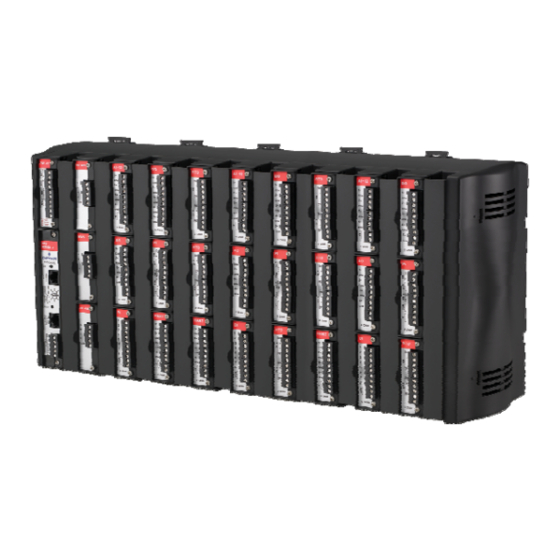
ROC800-Series Instruction Manual Power Supply Module Module (1 of 27 max) Wire Channel Cover LOI (Local Port) EIA-232 (RS-232D) Right End Cap Built-in Ethernet (Comm1) Built-in EIA-232 (RS-232C) (Comm2) Figure 1-2. ROC827 Base Unit with One Expansion Backplane (separated for clarity) I/O Modules The ROC800 and EXPs support various types of Input/Output (I/O) modules, which can satisfy a wide variety of field I/O requirements... -
Page 14: Central Processor Unit (Cpu)
ROC800-Series Instruction Manual Communication modules (which you install only in slots 1 [Comm3], 2 [Comm4], or 3 [Comm5] in the ROC800) provide additional ports for communicating with a host computer or other devices. Modules include: EIA-232 (RS-232C) – Point-to-point asynchronous serial communications include Data Terminal Ready (DTR) support, Ready To Send (RTS) support, and radio power control. -
Page 15: Real-Time Clock (Rtc)
ROC800-Series Instruction Manual Flash ROM (Read-Only Memory). SDRAM (Synchronous Dynamic Random Access Memory). Diagnostic monitoring. Real-Time Clock. Automatic self-tests. Power saving modes. Local Operator Interface (LOI) EIA-232 (RS-232D) Local Port. EIA-232 (RS-232C) serial Comm2 port. Ethernet Comm1 port. 1.3.2 Real-Time Clock (RTC) You can set the ROC800’s real-time clock (RTC) for year, month, day, hour, minute, and second. -
Page 16: Options
ROC800-Series Instruction Manual : The PM-24 module’s DC-to-DC converter supplies Note approximately 12 volts to the backplane, which is reflected in the on-screen values for points 1 through 3. 1.3.4 Options The ROC800 allows you to choose from a wide variety of options to suit many applications. -
Page 17: Firmware
If you experience trouble with this equipment or the dial-up modem, contact Emerson Process Management’s Remote Automation Solutions (at 641-754-3923) for repair or warranty information. If the equipment harms the telephone network, the telephone company may request that you disconnect the equipment until the problem is resolved. - Page 18 ROC800-Series Instruction Manual Input/Output Database. Historical Database. Event and Alarm Log Databases. Applications (PID, AGA, FST, and such). Measurement Station Support. Determining Task Execution. Real-Time Clock. Establishing and Managing Communications. Self-Test Capability. The firmware makes extensive use of configuration parameters, which you configure using ROCLINK 800 software.
- Page 19 ROC800-Series Instruction Manual defined configuration parameters for assigning values, statuses, or identifiers. The firmware scans each input, placing the values into the respective database point. These values are available for display and historical archiving. SRBX Spontaneous-Report-by-Exception (SRBX or RBX) communication allows the ROC800 to monitor for alarm conditions and, upon detecting an alarm, automatically reports the alarm to a host computer.
- Page 20 ROC800-Series Instruction Manual Addressing automatically switches to 8-point addressing if you add a fourth or fifth expansion backplane. The Series 2 ROC800 defaults to 8-point addressing. To switch to 16- point addressing, you must manually select this option. : To change input module addressing, select ROC > Device Note Information in ROCLINK 800.
-
Page 21: Historical Database And Event & Alarm Log
ROC800-Series Instruction Manual firmware is limited to measurements from gas meter runs, rather than liquids. Software supports most liquid-related capabilities; other firmware functions remain the same. 1.5.1 Historical Database and Event & Alarm Log The historical database provides archiving of measured and calculated values for either on-demand viewing or saving to a file. -
Page 22: Roc800 Flow Calculations
ROC800-Series Instruction Manual You can group meter runs among the maximum of twelve stations in any combination. Meter runs belong in the same station when they have the same gas composition data and calculation methods. Stations allow you to: Set contract hours differently for each station. Designate several individual meter runs as part of a station. -
Page 23: Roc800L Flow Calculations
ROC800-Series Instruction Manual 1.5.4 ROC800L Flow Calculations For the ROC800L, liquid calculation methods include: API 2450 (1980) ASTM-D1250-04, IP200/04 (same as MPMS Chapter 11) API Manual of Petroleum Measurement Standards (MPMS): Chapter 4.6 Pulse Interpolation (small volume proving) Chapter 5.5 Double Pulse Integrity (ISO 6551, IP252) Chapter 11.1 Volume Correction for Temperature and Pressure Chapter 11.2.1, 11.2.1M Pressure Correction (M is for metrics) Chapter 11.2.4 Light Hydrocarbons –... -
Page 24: Low Power Modes
ROC800-Series Instruction Manual A memory validity self-test is performed to ensure the integrity of memory. 1.5.6 Low Power Modes The ROC800 uses low power operation under predetermined conditions and supports two low power modes, Standby and Sleep. Standby The ROC800 uses this mode during periods of inactivity. When the operating system cannot find a task to run, the ROC800 enters Standby mode. -
Page 25: Function Sequence Table (Fst)
ROC800-Series Instruction Manual 1.5.8 Function Sequence Table (FST) The Function Sequence Table (FST) applications firmware gives analog and discrete sequencing control capability to the ROC800. This programmable control is implemented in an FST, which defines the actions the ROC800 performs using a series of functions. You use the FST Editor in ROCLINK 800 software to develop FSTs The function is the basic building block of an FST. - Page 26 ROC800-Series Instruction Manual first time, or when you need to make configuration changes off-line. Once you create a backup configuration file, you can load it into a ROC800 by using the Download function. Access to the ROC800 is restricted to authorized users with correct User ID and password.
-
Page 27: Roc800L Software
ROC800-Series Instruction Manual segment, you can configure the number of periodic history values archived, the frequency of archiving the periodic values, the number of daily values archived, and the contract hour. ROCLINK 800 can create an EFM (Electronic Flow Measurement) report file that contains all the configuration, alarms, events, periodic and daily history logs, and other history logs associated with the stations and meter runs in the ROC800. -
Page 28: Ds800 Development Suite Software
ROC800-Series Instruction Manual Proving: Controls meter proving by operating a four-way control valve, calculating a new meter factor, and storing meter factor information on up to 24 products for each of up to six meters. The program supports uni-directional, bi-directional, large volume, small volume, and master meter proving. -
Page 29: Expansion Backplane
ROC800-Series Instruction Manual Cross-reference (bindings) between variables in separate ROC800 units. Variable Dictionary. Off-line simulation for diagnostics and testing. On-line modification of programs. On-line debugging of programs. User developed functions and function blocks. User defined templates. Creation and support of user defined libraries. Expansion Backplane The expansion backplane is a key component to the ability of the ROC827 to expand its I/O capabilities to meet your needs. - Page 30 ROC800-Series Instruction Manual Table 1-5. Additional Technical Information Name Form Number Part Number ROC800 Remote Operations Controller ROC800:800 D301155X012 ROC800L Liquid Operations Controller ROC800:800L D301678X012 ROC800-Series Operating System Firmware ROC800:FW1 D301156X012 ROC800L Liquid Application Software ROC800:SW1 D301576X012 ™ Fieldbus Interface (ROC800-Series) ROC800:FFI D301650X012 OUNDATION...
-
Page 31: Chapter 2 - Installation And Use
ROC800-Series Instruction Manual Chapter 2 – Installation and Use This chapter describes the ROC800-Series housing (case), backplane (electronic connection board at the back of the housing), CPU (central processing unit), and the expansion backplane (EXP). This chapter provides a description and specifications of these hardware items and explains installation and startup of the ROC800-Series. -
Page 32: Environmental Requirements
ROC800-Series Instruction Manual 2.1.1 Environmental Requirements Always install the ROC800 in a user-supplied building or enclosure to protect it from direct exposure to rain, snow, ice, blowing dust or debris, and corrosive atmospheres. If you install the ROC800 outside of a building, it must be placed in a National Electrical Manufacturer’s Association (NEMA) 3 or higher rated enclosure to ensure the necessary level of protection. -
Page 33: Compliance With Hazardous Area Standards
ROC800-Series Instruction Manual The site must comply with class limits of Part 15 of the FCC rules. Operation is subject to the following two conditions: (1) The device may not cause harmful interference, and (2) the device must accept any interference received, including interference that may cause undesired operation. -
Page 34: Power Installation Requirements
ROC800-Series Instruction Manual 2.1.4 Power Installation Requirements Be sure to route power away from hazardous areas, as well as sensitive monitoring and radio equipment. Local and company codes generally provide guidelines for installations. Adhere rigorously to all local and National Electrical Code (NEC) requirements. The removable terminal blocks accept 12 to 22 American Wire Gauge (AWG) wiring. -
Page 35: I/O Wiring Requirements
ROC800-Series Instruction Manual Proper grounding of the ROC800 helps to reduce the effects of electrical noise on the ROC800’s operation and protects against lightning. Install a surge protection device at the service disconnect on DC voltage source systems to protect against lightning and power surges for the installed equipment. -
Page 36: Removing And Replacing End Caps
ROC800-Series Instruction Manual 2.3.1 Removing and Replacing End Caps Normal use and maintenance of the ROC800 does not typically require you to remove the end caps on the housing. Follow these procedures in case removal is necessary. To remove the end caps: Place the tip of a flat-blade screwdriver into the top pry hole of the end cap and loosen the end cap by pulling the handle of the screwdriver away from the backplane. -
Page 37: Removing And Installing Module Covers
ROC800-Series Instruction Manual 2.3.3 Removing and Installing Module Covers Before you insert an I/O or communications module, remove the module cover over the empty module slots in which you intend to install the modules. Although you are not required to remove the power to the ROC800 to perform this procedure, caution is always advisable when working with a powered ROC800. - Page 38 ROC800-Series Instruction Manual Figure 2-2. Bottom View of the ROC800 Figure 2-1. Side View of the ROC800 : The distance from the mounting panel to the front of the Note ROC800 is 174mm (6.85”). If you mount the ROC800 inside an enclosure and want to connect a cable to the LOI or Ethernet port, ensure adequate clearance for the cable and the enclosure door.
-
Page 39: Installing The Din Rail
2.4.2 Securing the ROC800 to the DIN Rail When placed correctly, the DIN rail catches (see Figure 2-3) secure the ROC to the DIN rail. Place the catches according to the following configuration: ROC809: Two catches. Revised Nov-10 Installation and Use... -
Page 40: Removing The Roc800 From The Din Rail
ROC800-Series Instruction Manual ROC827: One catch. ROC827 and one EXP: Place catches on ROC827 and EXP. ROC827 and two EXPs: Place catches on ROC827 and second EXP. ROC827 and three EXPs: Place catches on ROC827 and third EXP. ROC827 and four EXPs: Place catches on ROC827 and second and fourth EXP. -
Page 41: Attaching An Expansion Backplane
ROC800-Series Instruction Manual Removing the backplane from the housing is not recommended, as there are no field serviceable parts. If the backplane requires maintenance, please contact your local sales representative. 2.5.1 Attaching an Expansion Backplane To attach an EXP to an existing ROC827 base unit or to another EXP: 1. -
Page 42: Removing An Expansion Backplane
ROC800-Series Instruction Manual 2.5.2 Removing an Expansion Backplane : Before you remove an EXP, you must power down the ROC827, Note disconnect all wiring from all modules, and remove the entire unit from the DIN rail. Once the entire ROC827 is free of the DIN rail, you can detach an individual EXP. -
Page 43: Central Processing Unit (Cpu)
ROC800-Series Instruction Manual 4. Using a flat-bladed screwdriver, gently pry the plastic locking clips at the upper and lower back edge of the EXP housing away from their securing tabs. : Applying too much pressure breaks the plastic hooks. Note 5. -
Page 44: Cpu
ROC800-Series Instruction Manual Series 1 CPU Faceplate Series 2 CPU Faceplate (Gray) (Black) Securing Screw Securing Screw LED Button LED Button LOI – EIA-232 (RS-232D)x LOI – EIA-232 (RS-232D)x Status LED Status LED Ethernet Ethernet EIA-232 (RS-232C) EIA-232 (RS-232C) Securing Screw Securing Screw Figure 2-7. - Page 45 ROC800-Series Instruction Manual Table 2-1. CPU Connector Locations CPU Number Series 1 Series 2 Backplane connector Backplane connector Backplane connector Backplane connector Not Used Battery Backup Battery Backup Not Used LOI Port RJ-45 License Key Terminal Ethernet RJ-45 License Key Terminal License Key Terminal RS-232 Not Used...
-
Page 46: Removing The Cpu Module
ROC800-Series Instruction Manual Table 2-2. STATUS LED Functions Status LED Color Definitions Solution Continually Green ROC800 functioning normally. Low Battery Voltage alert. Charge battery. Continually System AI (Point number 1) LoLo Apply DC voltage source. Alarm. Flashing Green Firmware invalid. Update firmware. -
Page 47: Installing The Cpu Module
ROC800-Series Instruction Manual 2.6.2 Installing the CPU Module Failure to exercise proper electrostatic discharge precautions (such as Caution wearing a grounded wrist strap) may reset the processor or damage electronic components, resulting in interrupted operations. When working on units located in a hazardous area (where explosive gases may be present), make sure the area is in a non-hazardous state before performing procedures. -
Page 48: Installing A License Key
ROC800-Series Instruction Manual Figure 2-9. License Key 2.7.1 Installing a License Key Failure to exercise proper electrostatic discharge precautions (such as Caution wearing a grounded wrist strap) may reset the processor or damage electronic components, resulting in interrupted operations. When working on units located in a hazardous area (where explosive gases may be present), make sure the area is in a non-hazardous state before performing procedures. -
Page 49: Removing A License Key
ROC800-Series Instruction Manual Press the license key into the terminal until it is firmly seated. Refer to Figure 2-10. Replace the CPU faceplate and tighten the two captive screws. Replace the wire channel cover. Review Restarting the ROC800 in Chapter 6, Troubleshooting. Restore power to the ROC800. -
Page 50: Startup
ROC800-Series Instruction Manual Check the input power polarity before connecting power to the ROC800. Caution Incorrect polarity can damage the ROC800. When working on units located in a hazardous area (where explosive gases may be present), make sure the area is in a non-hazardous state before performing procedures. -
Page 51: Chapter 3 - Power Connections
ROC800-Series Instruction Manual Chapter 3 – Power Connections This chapter discusses the Power Input modules. It describes the modules, explains how to install and wire them, and provides worksheets to help you determine—and tune—the power requirements for the I/O and communications modules you can install in the ROC800 and the EXPs. - Page 52 ROC800-Series Instruction Manual the backplane. The ROC800 requires 11.5 to 14.5 Volts dc for proper operation. BAT+ / BAT– CHG+ / CHG– AUX+ / AUX– + / AUX – OVER TEMP LED Figure 3-1. 12 Volt dc Power Input Module The CHG+ and CHG–...
-
Page 53: 24-Volt Dc Power Input Module (Pm-24)
ROC800-Series Instruction Manual Table 3-1. 12 Volt dc Power Input Terminal Block Connections Terminal Blocks Definition Volts DC Maximum Range: 11.5 to 16 Volts dc BAT+ and BAT– Accepts 12 Volts dc nominal from an AC/DC converter or other 12 Volts dc Recommended Operating Range: 11.5 supply. -
Page 54: Auxiliary Output (Aux+ And Aux-)
ROC800-Series Instruction Manual + / – AUX+ / AUX– Figure 3-2. 24 Volt dc Power Input Module Table 3-3. 24 Volt dc Power Input Terminal Block Connections Terminal Blocks Definition Volts DC + and – Accepts 24 Volts dc nominal from an AC/DC converter 20 to 30 Volts dc or other 24 Volts dc supply. -
Page 55: Auxiliary Power Wiring For Pm-12 Module
ROC800-Series Instruction Manual PM-24 For the 24 volt Power Input module (PM-24), the AUX voltage is always 12 Volts dc minus ~0.7 Volts. AUX+ / AUX– is internally current-limited by a 0.5 Amp Positive Temperature Coefficient (PTC). If you need to cycle power to the radio or other device to reduce the load on the power source (a recommended practice when using batteries), use a Discrete Output (DO) module to switch power on and off. -
Page 56: Switched Auxiliary Output (Auxsw+ And Auxsw-)
ROC800-Series Instruction Manual Removing the To remove the auxiliary output fuse: Auxiliary Output Fuse Perform the procedure described in Section 3.3, Removing a Power Input Module. Remove the fuse located at F1 on the Power Input module. Installing the Auxiliary To re-install the auxiliary output fuse: Output Fuse Replace the fuse located at F1 on the Power Input module. -
Page 57: Determining Power Consumption
ROC800-Series Instruction Manual Determining Power Consumption Determining the power consumption requirements for a ROC800 configuration involves the following steps: Determine your ideal ROC800 configuration, which includes identifying all modules, device relays, meters, solenoids, radios, transmitters, and other devices that may receive DC power from the complete ROC800 configuration (base unit and EXPs). - Page 58 ROC800-Series Instruction Manual General Calculation To calculate the power requirements of a ROC800 configuration Process requires: Determine the kind and number of communication modules and the kind and number of expanded backplanes you are implementing. Enter those values in the Quantity Used column of Table 3-5. Multiply the P value by the Quantity Used.
- Page 59 ROC800-Series Instruction Manual Multiply the value in the Total for ROC800 Base Unit, Total for All Modules, and Other Devices by 0.25. Enter the result in the Power System Safety Factor (0.25) line. : This value represents a safety factor to the power system to Note account for losses and other variables not factored into the power consumption calculations.
-
Page 60: Di Modules
Power Consumption (mW) Quantity Sub-Total Device Used (mW) Description TYPICAL CPU and ROC809 Backplane Power Input Module PM-12 (60W 87.5 mA @ 12 volts dc 1050 mW max) Power Input Module PM-24 (24W 102.1 mA @ 24 volts dc 2450 mW max) Per Active LED –... -
Page 61: Tuning The Configuration
ROC800-Series Instruction Manual 3.2.1 Tuning the Configuration The PM-12 Power Input module can supply a maximum of 60 W (60,000 mW) to the backplane. The PM-24, when operating between –40°C to 55°C, can supply a maximum of 30 W (30000 mW) to the backplane. -
Page 62: Description
ROC800-Series Instruction Manual Table 3-6. Power Consumption of the Analog Input Module Power Consumption (mW) Quantity Duty Sub-Total I/O Module Used Cycle (mW) Description TYPICAL Analog Input 84 mA @ 12 volts dc 1008 mW AI Module Base Jumper set for +T @ 12 volts dc Channel’s mA current Channel 1 draw from +T * 1.25 * 12... - Page 63 ROC800-Series Instruction Manual Table 3-7. Power Consumption of the Analog Output Module Power Consumption (mW) Quantity Duty Sub-Total I/O Module Used Cycle (mW) Description TYPICAL AO Module Base 100 mA @ 12 volts dc 1200 mW Jumper set for +T @ 12 volts dc Channel’s mA current Channel 1 draw from +T * 1.25 * 12...
- Page 64 ROC800-Series Instruction Manual Table 3-8. Power Consumption of the Discrete Input Module Power Consumption (mW) Quantity Duty Sub-Total I/O Module Used Cycle (mW) Description TYPICAL 19 mA @ 12 volts dc No DI Module Base 228 mW Channels Active Channel 1 3.2 mA @ 12 volts dc 38.4 mW Channel 2...
- Page 65 ROC800-Series Instruction Manual Table 3-9. Power Consumption of the Discrete Output Module Power Consumption (mW) Quantity Duty Sub-Total I/O Module Used Cycle (mW) Description TYPICAL 20 mA @ 12 volts dc No DO Module 240 mW Channels Active Channel 1 1.5 mA 18 mW Channel 2...
- Page 66 ROC800-Series Instruction Manual Table 3-10. Power Consumption of the Discrete Output Relay Module Power Consumption (mW) Quantity Duty Sub-Total I/O Module Used Cycle (mW) Description TYPICAL 6.8 mA @ 12 volts dc DOR Module 81.6 mW No Channels Active 150 mA for 10 mSec 1800 mW Channel 1 during transition...
- Page 67 ROC800-Series Instruction Manual Table 3-11. Power Consumption of the High and Low Speed Pulse Input Module Power Consumption (mW) Quantity Duty Sub-Total I/O Module Used Cycle (mW) Description TYPICAL 21 mA @ 12 volts dc No PI Module 252 mW Channels Active Channel 1 7.4 mA...
- Page 68 ROC800-Series Instruction Manual Table 3-12. Power Consumption of the MVS Module Power Consumption (mW) Quantity Duty Sub-Total I/O Module Used Cycle (mW) Description TYPICAL MVS Module 112 mA @ 12 volts dc 1344 mW Per Active LED – Maximum 2 1.5 mA 18 mW 1.25 * Measured...
- Page 69 ROC800-Series Instruction Manual Table 3-14. Power Consumption of the APM Module Power Consumption (mW) Quantity Duty Sub-Total I/O Module Used Cycle (mW) Description TYPICAL APM Module 110 mA @ 12 volts dc 1300 mW 1.25 * Measured Power provided by the Current Draw (from +T module’s +T port port in mA) * 24...
-
Page 70: Removing A Power Input Module
ROC800-Series Instruction Manual Table 3-17. Power Consumption of the HART Module Power Consumption (mW) Quantity Duty Sub-Total Other Device Used Cycle (mW) Description TYPICAL HART Module Base 110 mA @ 12 volts dc 1320 mW Channel’s mA current Each Channel draw from +T * 2.50 * 12 Table Total Table 3-18. -
Page 71: Installing A Power Input Module
ROC800-Series Instruction Manual Remove the Power Input module. : If you intend to store the ROC800 for an extended period, also Note remove the internal backup battery located on the CPU module (see Figure 3-5). Battery Figure 3-5. Backup Battery on CPU Module Installing a Power Input Module To install the Power Input module: Failure to exercise proper electrostatic discharge precautions, such as... -
Page 72: Connecting The Roc800 To Wiring
ROC800-Series Instruction Manual Press the module firmly into the slot. Make sure the connectors at the back of the Power Input module fit into the connectors on the backplane. Tighten the two captive screws on the front of the Power Input module firmly (refer to Figures 3-1 and 3-2). -
Page 73: Volts Dc Power Supply And Bat+ / Bat
ROC800-Series Instruction Manual Insert each bared wire end into the appropriate power module connectors: For PM-12 (12 Volts dc source): into the clamp beneath the appropriate BAT+ and BAT– termination screws. For PM-24 (24 Volts dc source): into the clamp beneath the appropriate POWER INPUT+ and POWER INPUT–... -
Page 74: Wiring The External Batteries
ROC800-Series Instruction Manual Figure 3-7. 12 Volt dc Power Supply and CHG+ / CHG– Wiring Replace all other power sources (if necessary) to the ROC800. Review Restarting the ROC800 in Chapter 6, Troubleshooting. : Refer to Table 3-2 concerning LEDs. Note 3.5.2 Wiring the External Batteries You can use external batteries as the main source of power for the... - Page 75 ROC800-Series Instruction Manual Battery Reserve Battery reserve is the amount of time that the batteries can provide power without discharging below 20% of their total output capacity. The battery reserve should be a minimum of five days, with ten days of reserve preferred.
-
Page 76: Replacing The Internal Battery
ROC800-Series Instruction Manual 3.5.3 Replacing the Internal Battery The internal Sanyo 3 volt CR2430 lithium backup battery located on the CPU provides backup of the data and the Real-Time Clock when the main power is not connected. The battery has a one-year minimum backup life while the battery is installed and no power is applied to the ROC800. -
Page 77: Additional Technical Information
ROC800-Series Instruction Manual Insert a plastic screwdriver behind the battery and gently push the battery out of the battery holder. Note how the battery is oriented: the negative side of the battery (–) is placed against the CPU and the positive (+) towards the + label on the battery holder. Insert the new battery in the battery holder paying close attention to install the battery with the correct orientation. - Page 78 ROC800-Series Instruction Manual [This page is intentionally left blank.] 3-28 Power Connections Revised Nov-10...
-
Page 79: Chapter 4 - Input/Output Modules
ROC800-Series Instruction Manual Chapter 4 – Input/Output Modules This chapter describes the Input/Output (I/O) modules used with the ROC800 and expansion backplanes and contains information on installing, wiring, and removing those modules. In This Chapter I/O Module Overview ................4-1 Installation.................... -
Page 80: Optional I/O Module Locations
ROC800-Series Instruction Manual Terminal Blocks DOC0513A Front View Side View Figure 4-1. Typical I/O Module I/O Slot #4 I/O Slot #1 or Comm 3 I/O Slot #7 I/O Slot #5 I/O Slot #2 or Comm 3 or 4 I/O Slot #8 I/O Slot #6 I/O Slot #3 or I/O Slot #9... -
Page 81: Installation
ROC800-Series Instruction Manual Analog Output (AO), Discrete Output (DO), and Discrete Output Relay (DOR) modules that provide the ability to manage various control devices. Advance Pulse modules (APM) that provide advanced functionality (such as densitometer support) commonly found in liquids and gas measurement applications. -
Page 82: Removing And Installing Wire Channel Covers
ROC800-Series Instruction Manual Each I/O module installs in the ROC800 in the same manner. You can install any I/O module into any module socket, whether empty or in place of another module. The design of ROC800-Series communications and I/O modules Caution supports “hot-swapping”... -
Page 83: Installing An I/O Module
ROC800-Series Instruction Manual remove the power to the ROC800 to perform this procedure, caution is always advisable when working with a powered ROC800. To avoid circuit damage when working inside the unit, use appropriate Caution electrostatic discharge precautions (such as wearing a grounded wrist strap). -
Page 84: Removing An I/O Module
ROC800-Series Instruction Manual : If the module stops and will not go any further, do not force Note the module. Remove the module and see if the pins are bent. If the pins are bent, gently straighten the pins and re-insert the module. -
Page 85: Wiring I/O Modules
ROC800-Series Instruction Manual Remove the wire channel cover. Disconnect the field wiring. Unscrew the two captive screws holding the module in place. Gently pull the module’s lip out and remove the module from the slot. You may need to gently wiggle the module. Install a new module or install the module cover. -
Page 86: Analog Input Module Field Wiring
ROC800-Series Instruction Manual Manual (for ROC800-Series) (Form 6218) or the ROCLINK 800 Configuration Software User Manual (for ROC800L) (Form 6214). : The AI-16 module provides 16-bit resolution and uses a 24-bit Note A/D converter. DIP switches on the AI-16 module (see Figure 4- 6) allow you to select between current and voltage loop input. -
Page 87: Analog Output (Ao) Modules
ROC800-Series Instruction Manual On the AI-16 module, you use jumper J3 to configure the AI (+T) as 12 or 24 Volts dc. Additionally, two DIP switches on the module allow you to select between current and voltage loop input. I indicates current loop input;... -
Page 88: Discrete Input (Di) Modules
ROC800-Series Instruction Manual 12V / 24V dc Jumper Figure 4-7. Analog Output Jumper J4 (Shown Set to +12V) Representative Field Wiring Internal Circuit CURRENT LOOP CONTROL CURRENT LOOP DEVICE 4-20mA CURRENT LOOP ROC800 POWERED CONTROL CURRENT LOOP CONTROL CURRENT LOOP CONTROL 1-5 VOLT CONTROL DEVICE DOC0505A... -
Page 89: Discrete Input Module
ROC800-Series Instruction Manual The DI module provides a source voltage for dry relay contacts or for an open-collector solid-state switch. The DI module’s LEDs light when each input is active. Each DI channel can be software-configured to function as a momentary or latched DI (see the ROCLINK 800 Configuration Software User Manual (for ROC800-Series), Form 6218) or the ROCLINK 800 Configuration Software User Manual (for ROC800L) (Form 6214). -
Page 90: Pulse Input (Pi) Modules
ROC800-Series Instruction Manual Pulse Input (PI) Modules The Pulse Input (PI) module provides two channels for measuring either a low speed or high speed pulse signal. The PI module processes signals from pulse-generating devices and provides a calculated rate or an accumulated total over a configured period. -
Page 91: Field Wiring
ROC800-Series Instruction Manual +T 12 / 24 V dc Jumper Figure 4-10. Pulse Input J4 Jumper (Set to +12 V) Representative Field Wiring Internal Circuit OPEN DRAIN TYPE 12KHz PI FILTER & OPEN COLLECTOR DEVICE LEVEL DETECTION EXTERNALLY POWERED 125KHz PI FILTER & LEVEL DETECTION CONTACT-CLOSURE DEVICE EXTERNALLY POWERED... -
Page 92: Discrete Output (Do) Modules
ROC800-Series Instruction Manual Representative Field Wiring Internal Circuit 12KHz PI FILTER & OPEN COLLECTOR LEVEL DETECTION OPEN DRAIN TYPE DEVICE ROC800 POWERED METER COIL 2 CHAN DOC0511A Figure 4-12. ROC800-Powered Pulse Input Module Field Wiring You can induce ground loops by tying commons from various modules Caution together. -
Page 93: Discrete Output Relay (Dor) Modules
ROC800-Series Instruction Manual DO modules draw power for the active circuitry from the backplane, and are current-limited for protection against excessive current. : When using the Discrete Output module to drive an inductive Note load (such as a relay coil), place a suppression diode across the input terminals to the load. - Page 94 ROC800-Series Instruction Manual : Since the DOR latches, a power failure does not change the Note relay’s state. The relay retains the state (open or closed) it had upon failure. Figure 4-14 displays the field wiring connections to the output circuit of the DOR module.
-
Page 95: Resistance Temperature Detector (Rtd) Input Modules
ROC800-Series Instruction Manual Resistance Temperature Detector (RTD) Input Modules The Resistance Temperature Detector (RTD) module monitors the temperature signal from an RTD source. The module can accommodate input from a two-, three-, or four-wire RTD source. The active element of an RTD probe is a precision, temperature- dependent resistor made from a platinum alloy. -
Page 96: Advanced Pulse Module (Apm)
ROC800-Series Instruction Manual Terminal Label Definition CH2 Positive RTD – CH2 Negative RTD CH2 Constant Current – Not Used 4-Wire RTD 3-Wire RTD 2-Wire RTD Jumper Jumper White Jumper Figure 4-15. RTD Sensor Wiring Terminal Connections Figure 4-15 and Table 4-2 display the connections at the RTD terminals for the various RTD probes. - Page 97 ROC800-Series Instruction Manual and proving. Field wiring (see Figures 4-16 through 4-25) and DIP switch settings (see Figure 4-26 and Table 4-3) provide this flexibility. : The ROC800 can support up to 27 APMs. Note For densitometer inputs, you can designate channel 3 as a pulse input using a frequency input channel with hardware filtering for the Micro Motion (formerly Solartron) 7835/7845 densitometer (or similar current-modulated pulses).
- Page 98 ROC800-Series Instruction Manual DET SW 1 DET SW 2 DET SW 1 DET SW 2 Figure 4-20. Series Detector Switch (Normally Figure 4-21. Series Detector Switch Wiring Open) Wiring on APM (Normally Closed) on APM EXTERNALLY POWERED PREAMP EXTERNALLY POWERED METER PREAMP COIL 1...
-
Page 99: Dip Switches
ROC800-Series Instruction Manual Figure 4-25. DIP Switches on APM Table 4-3. APM DIP Switch Settings Switch Channel Side Function Switch Position Standard PI Current Modulated Densitometer Down Left 10 kΩ Pullup to 12 V dc Left No Pullup Resistor Down Right 10 kΩ... -
Page 100: Thermocouple (Tc) Input Module
ROC800-Series Instruction Manual 4.11 Thermocouple (TC) Input Module The TC module is currently NOT supported in the Series 2 CPU or the Caution ROC800L. The five-channel Thermocouple Input module monitors either the J or K type thermocouple (TC), based on how you configure the module with ROCLINK 800 Configuration software. - Page 101 ROC800-Series Instruction Manual thermocouple leads short and use a thermocouple extension wire to run between the thermocouple and measuring instrument. The thermocouple connects directly to the module’s removable terminal block. No special terminal or isothermal block is required. J OR K THERMOCOUPLE UNGROUNDED SHEATH DOC0512B Figure 4-26.
- Page 102 ROC800-Series Instruction Manual Millivolt signals are very small and are very susceptible to noise. Noise Susceptibility Noise from stray electrical and magnetic fields can generate voltage signals higher than the millivolt levels generated from a thermocouple. The T/C modules can reject common mode noise (signals that are the same on both wires), but rejection is not perfect, so minimize noise where possible.
-
Page 103: Highway Addressable Remote Transducer (Hart)
ROC800-Series Instruction Manual Use an ungrounded junction for measurements in corrosive environments where it is desirable to have the thermocouple electronically isolated from and shielded by the sheath. The welded wire thermocouple is physically insulated from the thermocouple sheath by MgO powder (soft). - Page 104 ROC800-Series Instruction Manual In multi-drop mode, you can connect up to five HART devices (in Multi-drop Mode parallel) to each analog input channel. As with the point-to-point mode, digital communications are superimposed on the 4 to 20 milliAmp signal. However, the analog signal is used only to measure the current consumed by the multi-drop loop.
-
Page 105: Hart Module
ROC800-Series Instruction Manual HART device, or in parallel to the negative terminals of the HART devices. Switches on the module board allow channel-by-channel selection as an Analog Input (IN) or Analog Output (OUT). The switches for Channel 2 and 4 are located on the front of the module, while the switches for channel 1 and 3 are located on the back of the module. -
Page 106: Multi-Variable Sensor Input/Output (Mvs I/O)
ROC800-Series Instruction Manual CH2 I/O Switch CH4 I/O Switch Figure 4-34. HART Channels 2 and 4 (front side of board) 4.13 Multi-Variable Sensor Input/Output (MVS I/O) The Multi-Variable Sensor Input/Output (MVS I/O) module provides an interface to a sensor that provides differential pressure, static pressure, and temperature inputs for the ROC800 for orifice flow calculation. - Page 107 ROC800-Series Instruction Manual The MVS I/O module consists of interface electronics that provide the communications link between the ROC800 and the MVS devices. The interface electronics controls communications with the sensor module, provides scaling of process variables, aids calibration, stores operating parameters, performs protocol conversion, and responds to requests from the ROC800.
- Page 108 ROC800-Series Instruction Manual Following are field wiring diagrams for the MVS and MVS I/O modules. Figure 4-37. MVS Field Wiring Figure 4-38. MVS I/O Field Wiring : A “star” configuration for transmitters may not be reliable. Note Terminations are recommended for long distances (greater that 1000 meters) at the extreme ends of the circuit.
- Page 109 ROC800-Series Instruction Manual Figure 4-39. MVS Jumper J4 (Shown Not Terminated) Four wires run from the MVS module terminal block and connect to the sensor. The wires should be a minimum size of 22 AWG and a maximum length of 1220 m (4000 ft). : Insulated, shielded, twisted-pair wiring is required when using Note MVS signal lines.
-
Page 110: Alternating Current Input/Output (Ac I/O) Module
ROC800-Series Instruction Manual 4.14 Alternating Current Input/Output (AC I/O) Module EMC issues restrict the use of the ACIO module only to devices using a Warning PM-12 power module. You cannot use the ACIO module in a device that uses a PM-24 power module. The module has one bank of 6 DIP switches on its daughterboard (see Switchable I/O and Figure 4-36), which controls the input/output status of each of the six... - Page 111 ROC800-Series Instruction Manual EXTERNAL AC PWR/PERMISSIVE SOURCE SOLID-STATE RELAY CONTROL AC CONTROLLED DEVICE SOLID-STATE RELAY CONTROL AC CONTROLLED DEVICE Figure 4-41. AC I/O Module (Output Field Wiring) : If the label on your AC I/O module does not indicate 120/240V, Note your module is designed for use only with 120V.
- Page 112 ROC800-Series Instruction Manual : If the label on your AC I/O module does not indicate 120/240V, Note your module is designed for use only with 120V. Additionally, all AC wiring must be shielded. Table 4-6. Field Wiring Terminals Terminal Label Definition AC In AC Input (Permissive Power)
-
Page 113: Additional Technical Information
ROC800-Series Instruction Manual 4.15 Additional Technical Information Refer to the following technical documentation (available at www.EmersonProcess.com/Remote) for additional and most-current information on each of the I/O modules. Table 4-7. I/O Module Technical Specifications Name Form Number Part Number ROC800-Series Analog Input Modules ROC800:AI D301238X012 ROC800-Series Analog Output Module... - Page 114 ROC800-Series Instruction Manual [This page is intentionally left blank.] 4-36 Input/Output Modules Revised Nov-10...
-
Page 115: Chapter 5 - Communications
ROC800-Series Instruction Manual Chapter 5 – Communications This chapter describes the built-in communication ports and the optional communication modules used with the ROC800. In This Chapter Communication Ports and Modules Overview........5-1 Installing Communication Modules ............5-3 Removing a Communication Module............. 5-4 Wiring Communication Modules ............ - Page 116 ROC800-Series Instruction Manual Optional Comm 3 (Slot #1) Optional Comm 3 or Comm 4 (Slot #2) LOI (Local Port) EIA-232 (RS-232D) Built-in Ethernet (Comm1) Optional Comm 3 to Comm 5 (Slot #3) Built-in EIA-232 (RS-232) (Comm2) Figure 5-1. Communication Ports Table 5-2.
-
Page 117: Installing Communication Modules
ROC800-Series Instruction Manual Installing Communication Modules All communication modules install into the ROC800 in the same way. The design of ROC800-Series communication and I/O modules supports Caution “hot-swapping” (replacing similar modules in the same slot) and “hot- plugging” (inserting modules into an empty slot) while the ROC800 is powered. -
Page 118: Removing A Communication Module
ROC800-Series Instruction Manual : Leaving the wire channel cover in place can prevent the Note module from correctly connecting to the socket on the backplane. Perform one of the following: If there is a module currently in the slot, unscrew the captive screws and remove that module (refer to Removing a Communication Module). -
Page 119: Wiring Communication Modules
ROC800-Series Instruction Manual Unscrew the two captive screws holding the module in place. Gently pull the module’s lip out and remove the module from the slot. You may need to gently wiggle the module. Install a new module or install the module cover. Screw the two captive screws to hold the module cover in place. - Page 120 ROC800-Series Instruction Manual operation. The RJ-45 connector pin uses the data terminal equipment (DTE) in the IEEE standard. The LOI port supports ROC Plus and Modbus protocol communication. The LOI also supports the log-on security feature of the ROC800 if you have enabled the Security on LOI in the ROCLINK 800 software.
-
Page 121: Using The Loi
ROC800-Series Instruction Manual RJ-45 Pins Wire on ROC800- Color Series Blue Orange Black Green Yellow Brown Gray 5.5.1 Using the LOI Plug the LOI cable into the LOI RJ-45 connector of the ROC800. Connect the LOI cable to the D-Sub 9 pin (F) to RJ-45 modular converter. - Page 122 ROC800-Series Instruction Manual The Medium Access Control (MAC) mechanism embedded in each station interface determines access to the shared medium. The MAC mechanism is based on Carrier Sense Multiple Access with Collision Detection (CSMA/CD). If two stations begin to transmit a packet at the same instant, the stations stop transmitting (Collision Detection).
-
Page 123: Rs-232) Serial Communication
ROC800-Series Instruction Manual Signal coupling between the different cable pairs contained within a multi-pair cable bundle causes “crosstalk.” 10BASE-T transceivers are designed so that you do not need to be concerned about cable crosstalk, provided the cable meets all other requirements. Noise can be caused by crosstalk of externally induced impulses. -
Page 124: Eia-422/485 (Rs-422/485) Serial Communications Module
ROC800-Series Instruction Manual LOI – Local Port EIA-232 (RS-232D). Refer to Section 5.5, Local Operator Interface. Built-in – Comm2 EIA-232 (RS-232C). Module – Comm3 to Comm5 EIA-232 (RS-232C). EIA-232 (RS-232) uses point-to-point asynchronous serial communication and is commonly used to provide the physical interface for connecting serial devices, such as gas chromatographs and radios to the ROC800-Series. -
Page 125: Eia-422/485 (Rs-422/485) Jumpers & Termination Resistors
ROC800-Series Instruction Manual used to multi-drop units on a serial network over long distances using inexpensive twisted-pair wiring. EIA-422 (RS-422) drivers are designed for party-line applications where one driver is connected to, and transmits on, a bus with up to ten receivers. - Page 126 ROC800-Series Instruction Manual Terminations are required on the two EIA-422/485 (RS-422/485) communication modules located at the extremities of the circuit. That is to say, the two outside modules require terminations in order to complete the communication circuit. Figure 5-5. EIA-422/485 (RS-422/485) Jumpers Table 5-11.
-
Page 127: Dial-Up Modem Communication Module
ROC800-Series Instruction Manual Dial-up Modem Communication Module The dial-up modem module interfaces to a Public-Switched Telephone Network (PSTN) line, and requires a telephone line connection. The module provides a telephone interface on the host port that is capable of both answering and originating telephone calls. The module also provides electronics that conserve power when the phone line is not in use. -
Page 128: Multi-Variable Sensor (Mvs) Interface Module
ROC800-Series Instruction Manual Notes If you are installing a modem module, it is recommended that you install a surge protector between the RJ-11 jack and the outside line. The dial-up modem is not hot-swappable or hot-pluggable. When installing a dial-up modem module, you must remove power from the ROC800. -
Page 129: Additional Technical Information
ROC800-Series Instruction Manual 5.11 Additional Technical Information Refer to the following technical documentation (available at www.EmersonProcess.com/Remote) for additional and most-current information. Table 5-15. Communication Modules Technical Specifications Name Form Number Part Number ROC800-Series Communication Modules ROC800:COM D301171X012 MVS205 Multi-Variable Sensor 2.5:MVS205 D301079X012 MVS205 Multi-Variable Sensor (ATEX/IECEx Version) - Page 130 ROC800-Series Instruction Manual [This page is intentionally left blank.] 5-16 Communications Revised Nov-10...
-
Page 131: Chapter 6 - Troubleshooting
ROC800-Series Instruction Manual Chapter 6 – Troubleshooting This chapter provides generalized guidelines for troubleshooting the ROC800-Series. Perform the procedures in this chapter before you remove power from the ROC800 for any reason, after you restore power to the ROC800, and if you disassemble the ROC800. Use the following tools for troubleshooting: IBM-compatible personal computer. -
Page 132: Checklists
ROC800-Series Instruction Manual Checklists If the LEDs do not display: By default, LEDs on the communication modules and I/O modules enter Sleep mode after five minutes. To turn the LEDs on, press the LED button located on the CPU for one second. -
Page 133: I/O Point
ROC800-Series Instruction Manual 6.2.2 I/O Point If you are experiencing troubles with an I/O point (Analog Input, Analog Output, Discrete Input, Discrete Output, Pulse Input, RTD Input, or Thermocouple Input): Check (using ROCLINK 800 software) to see how the channel is configured. -
Page 134: Powering Up
ROC800-Series Instruction Manual procedure: Remove power from the ROC800. Press and hold the RESET button on the CPU. : Use a small screwdriver or a straightened paper clip to press Note the RESET button. While holding down the RESET button, restore power to the ROC800. -
Page 135: Preserving Configuration And Log Data
ROC800-Series Instruction Manual 6.3.1 Preserving Configuration and Log Data Perform this backup procedure before you remove power from the ROC800 for repairs, troubleshooting, or upgrades, This procedure preserves the current ROC800 configuration and log data held in SDRAM. When working on units located in a hazardous area (where explosive Caution gases may be present), make sure the area is in a non-hazardous state before performing procedures. -
Page 136: Troubleshooting Analog Input Modules
ROC800-Series Instruction Manual Launch ROCLINK 800 software, log in, and connect to the ROC800. Verify that the configuration is correct. If major portions or the entire configuration needs to be reloaded, perform the remaining steps. Select File > Download. Select the backup configuration file (with file extension *.800) from the Open dialog box. -
Page 137: Troubleshooting Analog Output Modules
ROC800-Series Instruction Manual Verify the following readings: When the Value is –25% of span as configured in Table 6-1, it is an indication of no current flow (0 mA), which can result from open field wiring or a faulty field device. The multimeter should show 0 (zero) Volts dc. - Page 138 ROC800-Series Instruction Manual Failure to exercise proper electrostatic discharge precautions, such as Caution wearing a grounded wrist strap may reset the processor or damage electronic components, resulting in interrupted operations. To calibrate the module: Connect a multimeter between the + and – channel terminals of the module and set the multimeter to measure current in milliamps.
-
Page 139: Troubleshooting Discrete Input Modules
ROC800-Series Instruction Manual 6.3.5 Troubleshooting Discrete Input Modules Equipment Required Jumper wire PC running ROCLINK 800 software Failure to exercise proper electrostatic discharge precautions, such as Caution wearing a grounded wrist strap may reset the processor or damage electronic components, resulting in interrupted operations. Disconnect the field wiring at the DI module terminations. -
Page 140: Troubleshooting Discrete Output Relay Modules
ROC800-Series Instruction Manual 6.3.7 Troubleshooting Discrete Output Relay Modules Equipment Required Multimeter PC running ROCLINK 800 software Failure to exercise proper electrostatic discharge precautions, such as Caution wearing a grounded wrist strap may reset the processor or damage electronic components, resulting in interrupted operations. Connect the multimeter set up to measure ohms to the channel that you are testing. -
Page 141: Troubleshooting Rtd Input Modules
ROC800-Series Instruction Manual Set the frequency counter to count pulses. Verify (using ROCLINK 800 software) that the count read by the counter and the ROC800 are the same. Remove the test equipment, and reconnect the field device. 6.3.9 Troubleshooting RTD Input Modules The RTD module is similar in operation to an Analog Input module and uses the same troubleshooting and repair procedures. -
Page 142: Troubleshooting Thermocouple Input (T/C) Modules
ROC800-Series Instruction Manual Verify that the Raw A/D Input value changed and reflects the Adjusted A/D 0% value. Change the resistance to reflect a high temperature as determined by the temperature-to-resistance conversion chart. Verify that the Raw A/D Input value changed and reflects the Adjusted A/D 100% value. -
Page 143: Troubleshooting Advanced Pulse Modules
ROC800-Series Instruction Manual Disconnect the thermocouple from the ROC800. Connect the thermocouple directly to the multimeter and verify the reading is correct by comparing it to a certified temperature measurement device connected to the process temperature the T/C is measuring. Remove the test equipment, and reconnect the field device. - Page 144 ROC800-Series Instruction Manual Failure to exercise proper electrostatic discharge precautions, such as Caution wearing a grounded wrist strap may reset the processor or damage electronic components, resulting in interrupted operations. To verify high-speed operation: Disconnect the field wiring at the APM module terminations. Connect to ROCLINK 800 software.
-
Page 145: Chapter 7 - Calibration
ROC800-Series Instruction Manual Chapter 7 – Calibration This chapter provides overview information about calibration procedures for the Analog Input (AI) modules, HART module, RTD Input module, and Multi-Variable Sensor modules (MVS and MVS I/O). For the full calibration procedure, refer to the ROCLINK 800 Configuration Software User Manual (for ROC800L) (Form A6214). -
Page 146: Preparing For Calibration
ROC800-Series Instruction Manual 7.3 Preparing for Calibration Before calibrating the inputs from a sensor, HART device, or other device, you should prepare the ROC800. Verify the inputs are correctly wired. For information on wiring the inputs, refer to Chapter 4, Input/Output Modules. If you are calibrating a pressure sensor input, be sure to remove the sensor from the flow as directed in the calibration procedure in the ROCLINK 800 Configuration Software User Manual (for ROC800-... -
Page 147: Appendix A - Glossary
ROC800-Series Instruction Manual Appendix A – Glossary : This is a generalized glossary of terms. Not all the terms may Note necessarily correspond to the particular device or software described in this manual. For that reason, the term “ROC” is used to identify all varieties of remote operations controllers (including ROC800-Series, ROC800L, ROC300-Series, ™... - Page 148 ROC800-Series Instruction Manual A preset, quantity-based product delivery or blended component delivery of a single Batch recipe. Blend Stream A product stream blended of both gasoline and ethanol. Blending The process of mixing two or more liquid components to form a composite delivered stream.
-
Page 149: Discrete Input
ROC800-Series Instruction Manual Crosstalk The amount of signal that crosses over between the receive and transmit pairs, and signal attenuation, which is the amount of signal loss encountered on the Ethernet segment. Canadian Standards Association. See http://www.csa.ca. CSMA/CD Carrier Sense Multiple Access with Collision Detection. Clear to Send modem communications signal. - Page 150 Compressibility Factor. Frequency Shift Keypad. Function Sequence Table, a type of user-written program in a high-level language designed by Emerson Process Management’s Remote Automation Solutions Division. Foot or feet. Ground Fault Analysis. Electrical ground, such as used by the ROC unit’s power supply.
- Page 151 ROC800-Series Instruction Manual A low-bandwidth communication protocol used among fieldbus devices and an HSE server. ® HART Highway Addressable Remote Transducer. Holding Analog output number value to be read. Register High-speed Ethernet; a high-bandwidth communications protocol used among Ethernet devices, frequently used between a client and an HSE server. Differential pressure.
- Page 152 ROC800-Series Instruction Manual Liquid Crystal Display. Local Display Panel, a display-only device that plugs into ROC300 (via a parallel interface cable) used to access information stored in the ROC. Light-Emitting Diode. Load For sequential blending: In multi-component blending, a load is the completed delivery of one component of a batch.
- Page 153 ROC800-Series Instruction Manual Meter Factor A number obtained by dividing the actual volume of liquid passed through a flow meter during a meter proving operation by the volume registered by the flow meter. The meter factor is used in flow calculations to correct the indicated volume (end flow meter registration minus start flow meter registration) to the observed gross volume (actual flow meter throughput at operating conditions).
-
Page 154: Pulse Input
ROC800-Series Instruction Manual P, Q A property of a point that typically can be configured or set. For example, the Point Tag Parameter ID is a parameter of an Analog Input point. Parameters are normally edited by using configuration software running on a PC. Personal Computer. - Page 155 ROC800-Series Instruction Manual The resulting amount of product measured after compensation for operational Quantity temperature and pressure, indicated in one of the following corrected units: cubic meters, liters, barrels, gallons. Rack A row of slots on a ROC into which I/O modules can be plugged. Racks are given a letter to physically identify the location of an I/O channel (such as “A”...
- Page 156 ROC800-Series Instruction Manual Script An uncompiled text file (such as keystrokes for a macro) that a program interprets in order to perform certain functions. Typically, the end user can easily create or edit scripts to customize the software. Side Stream The controlled stream, often called the ethanol product.
- Page 157 ROC800-Series Instruction Manual Volts. The actual space occupied by the product measured, indicated in one of the following Volume actual units: cubic meters, liters, barrels, gallons. Wild Stream Wild stream is the uncontrolled stream, often referring to the gasoline product. This is because the gasoline product cannot be exclusively metered, controlled, or measured.
- Page 158 ROC800-Series Instruction Manual [This page is intentionally left blank.] A-12 0BGlossary Revised Nov-10...
-
Page 159: Appendix B - Wiring Diagrams
ROC800-Series Instruction Manual Appendix B – Wiring Diagrams This appendix presents wiring examples for several standard Emerson devices. For other devices, refer to the manufacturer’s specifications. Daniel Senior Sonic Meter to PI Module DANIEL SENIOR SONIC METER 12KHz PI FILTER &... -
Page 160: Daniel 1818A And 1838 Turbine Pre-Amp To Pi Module
ROC800-Series Instruction Manual Daniel 1818A and 1838 Turbine Pre-Amp to PI Module DANIEL PREAMP TURBINE 1818A PICKUP METER COIL 15-28 VDC 12KHz PI FILTER & LEVEL DETECTION SQR. WAVE COMMON 12KHz PI FILTER & TURBINE LEVEL DETECTION PICKUP METER COIL 15-28 VDC SQR. -
Page 161: Micro Motion Rft9739 & 2400S Transmitters To Pi Module
ROC800-Series Instruction Manual Micro Motion RFT9739 & 2400S Transmitters to PI Module MICRO MOTION RFT9739 TRANSMITTER 12KHz PI FILTER & LEVEL DETECTION 12KHz PI FILTER & LEVEL DETECTION MICRO MOTION RFT9739 TRANSMITTER DOC0740A MICRO MOTION 2400S TRANSMITTER 12KHz PI FILTER & LEVEL DETECTION 12KHz PI FILTER &... -
Page 162: Micro Motion Rft9739 & 2400S Transmitters To Apm Module
ROC800-Series Instruction Manual Micro Motion RFT9739 & 2400S Transmitters to APM Module MICRO MOTION RFT9739 TRANSMITTER MICRO MOTION RFT9739 TRANSMITTER MICRO MOTION 2400S TRANSMITTER MICRO MOTION 2400S TRANSMITTER Wiring Diagrams Revised Nov-10... -
Page 163: 3- And 4-Wire Rtd To Rtd Module
ROC800-Series Instruction Manual 3- and 4-Wire RTD to RTD Module 4 - WIRE RTD 3 - WIRE RTD Revised Nov-10 Wiring Diagrams... -
Page 164: Daniel Senior Sonic Meter To Apm Module
ROC800-Series Instruction Manual Daniel Senior Sonic Meter to APM Module DANIEL SENIOR SONIC METER DANIEL SENIOR SONIC METER Wiring Diagrams Revised Nov-10... -
Page 165: Daniel 1818A And 1838 Dual Turbine Pre-Amp To Apm Module
ROC800-Series Instruction Manual Daniel 1818A and 1838 Dual Turbine Pre-Amp to APM Module DANIEL PREAMP TURBINE 1818A PICKUP METER COIL 15-28 VDC SQR. WAVE COMMON TURBINE PICKUP METER COIL 15-28 VDC SQR. WAVE COMMON DANIEL PREAMP 1818A TURBINE PICKUP DANIEL PREAMP METER COIL 1838... -
Page 166: Daniel 1818A And 1838 Turbine Pre-Amp To Apm Module
ROC800-Series Instruction Manual Daniel 1818A and 1838 Turbine Pre-Amp to APM Module DANIEL PREAMP TURBINE 1818A PICKUP METER COIL 15-28 VDC SQR. WAVE COMMON PICKUP 15-28 VDC COIL SQR. WAVE COMMON DANIEL PREAMP 1818A TURBINE PICKUP DANIEL PREAMP METER COIL 1838 PICKUP COIL... -
Page 167: Two-Stage Valve With Two Limit Switches To Acio Module
ROC800-Series Instruction Manual Two-Stage Valve with Two Limit Switches to ACIO Module PERMISSIVE POWER AC L1 PERMISSIVE NEUTRAL UPSTR N.O. MICRO SWITCH DNSTR N.C. MICRO SWITCH UPSTREAM SOLENOID N.O. DOWNSTREAM SOLENOID N.C. Revised Nov-10 Wiring Diagrams... - Page 168 ROC800-Series Instruction Manual [This page is intentionally left blank.] B-10 Wiring Diagrams Revised Nov-10...
-
Page 169: Index
ROC800-Series Instruction Manual Index Attaching an EXP............2-11 Automatic Self Tests ..........1-17 AUX Terminal...............3-2 +12 V dc AUX+ and AUX– ........... 3-2, 3-3, 3-4 Analog Input ............4-8 LEDs ...............3-3 Pulse Input ............4-12 Auxiliary +24 V dc Wiring ..............3-4 Analog Input ............4-8 Auxiliary Output............3-4 Pulse Input ............4-12 Auxiliary Output Fuse... - Page 170 ROC800-Series Instruction Manual CPU................2-18 EIA-422/485 (RS-422/485) Communication Connector Locations..........2-15 Jumpers and Termination Resistors ..... 5-12 Description ............. 1-8 LEDs..............5-12 Installing ............... 2-17 modules..............5-11 Removing ............. 2-16 Selecting 422 or 485 Mode........5-12 Series 1 and 2 ............2-13 Termination ............
- Page 171 ROC800-Series Instruction Manual 4-10. Pulse Input J4 Jumper (at +12V)....4-13 4-11. Externally Powered Pulse Input Module Field Hardware ..............1-5 Wiring..............4-13 Hardware Watchdog ..........1-17 4-12. ROC800-Powered Pulse Input Module Field HART Interface module ..........4-25 Wiring..............4-14 HART Pass-Through license key .......4-25 4-13. Discrete Output Module Field Wiring....4-15 Hazardous Area ............2-3 4-15.
- Page 172 See RTD Inputs ............ 4-17 LEDs..............4-31 Restarting the ROC800 ..........6-5 MVS..............5-15 ROC800L Firmware ..........1-15 MVS I/O..............4-28 ROC809 ..............1-5 Termination ............4-30 ROC827 ..............1-5 Wiring ..............4-31 ROCLINK 800 Configuration Software ...... 1-19 RTD Input modules Troubleshooting............
- Page 173 3- 1. 12 V dc Power Input Terminal Block Connections3-3 FFI.................1-23 3-2. 12 V dc Power Input LED Indicators ....3-3 ROC800 ..............1-23 3-3. 24 Vdc Power Input Terminal Block Connections ROC809 ..............1-23 ................3-4 ROC829 ..............1-23 3-4. 24 Vdc Power Input LED Indicators ....3-4 TEMP 3-5.
- Page 174 3- and 4-Wire RTD ..........B-5 If you have comments or questions regarding this manual, please direct them to your local sales representative or contact: Emerson Process Management Remote Automation Solutions Marshalltown, IA 50158 U.S.A. Houston, TX 77065 U.S.A. Pickering, North Yorkshire UK Y018 7JA Website: www.EmersonProcess.com/Remote...