Table of Contents
Advertisement
Notes: This model is based on RX-D55EG-K. Please refer to the original service manual
(Order no. PSG1004005CE).
TABLE OF CONTENTS
1 Safety Precautions----------------------------------------------- 3
1.1. General Guidelines---------------------------------------- 3
1.2. Before Repair and Adjustment ------------------------- 4
1.3. Caution For Fuse Replacement------------------------ 4
1.4. Protection Circuitry ---------------------------------------- 4
1.5. Safety Part Information----------------------------------- 4
2 Warning -------------------------------------------------------------- 5
to Electrostatically Sensitive (ES) Devices---------- 5
2.2. Precaution of Laser Diode------------------------------- 6
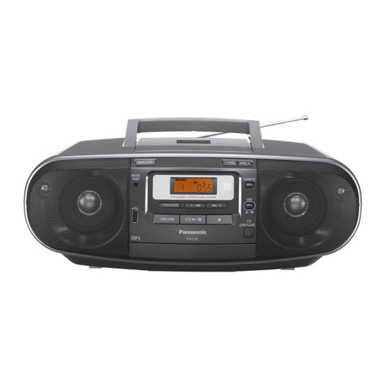
Portable Stereo CD System
Model No.
Product Color: (K)...Black Type
PAGE
2.4. Handling Precaution for Traverse Unit----------------8
3 Service Navigation --------------------------------------------- 10
3.1. Service Information -------------------------------------- 10
3.2. Notes -------------------------------------------------------- 10
3.3. Different Points ------------------------------------------- 11
4 Specifications ---------------------------------------------------- 12
5 Illustration of IC's, Transistors and Diodes ------------ 13
6 Schematic Diagram -------------------------------------------- 15
6.1. MAIN CIRCUIT (1/6) ------------------------------------ 15
6.2. MAIN CIRCUIT (2/6) ------------------------------------ 16
6.3. MAIN CIRCUIT (3/6) ------------------------------------ 17
© Panasonic Corporation 2010. All rights reserved.
Unauthorized copying and distribution is a violation of
law.
RX-D55EE
PSG1005030AE
PAGE
Advertisement
Table of Contents

Related Manuals for Panasonic RX-D55EE


Summary of Contents for Panasonic RX-D55EE
-
Page 1: Table Of Contents
2.2. Precaution of Laser Diode------------------------------- 6 6.2. MAIN CIRCUIT (2/6) ------------------------------------ 16 2.3. Service caution based on Legal restrictions -------- 7 6.3. MAIN CIRCUIT (3/6) ------------------------------------ 17 © Panasonic Corporation 2010. All rights reserved. Unauthorized copying and distribution is a violation of law. - Page 2 6.4. MAIN CIRCUIT (4/6) ------------------------------------ 18 6.5. MAIN CIRCUIT (5/6) ------------------------------------ 19 6.6. MAIN CIRCUIT (6/6) ------------------------------------ 20 6.7. POWER CIRCUIT---------------------------------------- 21 7 Printed Circuit Board ------------------------------------------ 22 7.1. MAIN P.C.B. ----------------------------------------------- 22 7.2. DECK P.C.B. ---------------------------------------------- 23 7.3. POWER, BATTERY (1), BATTERY (2) & MUSIC PORT P.C.B.
-
Page 3: Safety Precautions
1 Safety Precautions 1.1. General Guidelines 1. When servicing, observe the original lead dress. If a short circuit is found, replace all parts which have been overheated or damaged by the short circuit. 2. After servicing, see to it that all the protective devices such as insulation barriers, insulation papers shields are properly installed. -
Page 4: Before Repair And Adjustment
1.2. Before Repair and Adjustment Caution : DO NOT SHORT-CIRCUIT DIRECTLY (with a screwdriver blade, for instance), as this may destroy solid state devices. After repairs are completed, restore power gradually using a variac, to avoid overcurrent. • Current consumption at AC 230V, 50Hz in TUNER mode at volume (min) should be (~300 mA). 1.3. -
Page 5: Warning
2 Warning 2.1. Prevention of Electro Static Discharge (ESD) to Electrostatically Sensi- tive (ES) Devices Some semiconductor (solid state) devices can be damaged easily by static electricity. Such components commonly are called Elec- trostatically Sensitive (ES) Devices. Examples of typical ES devices are integrated circuits and some field-effect transistors and semiconductor “chip”... -
Page 6: Precaution Of Laser Diode
2.2. Precaution of Laser Diode CAUTION! THIS PRODUCT UTILIZES A LASER. USE OF CONTROLS OR ADJUSTMENTS OR PERFORMANCE OF PROCEDURES OTHER THAN THOSE SPECIFIED HEREIN MAY RESULT IN HAZARDOUS RADIATION EXPOSURE. Caution: This product utilizes a laser diode with the unit turned "on", invisible laser radiation is emitted from the pickup lens. Wavelength: 795 nm (CD) Maximum output radiation power from pickup: 100 μW/VDE Laser radiation from the pickup unit is safety level, but be sure the followings:... -
Page 7: Service Caution Based On Legal Restrictions
2.3. Service caution based on Legal restrictions 2.3.1. General description about Lead Free Solder (PbF) The lead free solder has been used in the mounting process of all electrical components on the printed circuit boards used for this equipment in considering the globally environmental conservation. The normal solder is the alloy of tin (Sn) and lead (Pb). -
Page 8: Handling Precaution For Traverse Unit
2.4. Handling Precaution for Traverse Unit The laser diode in the optical pickup unit may break down due to static electricity of clothes or human body. Special care must be taken avoid caution to electrostatic breakdown when servicing and handling the laser diode in the traverse unit. Cautions to Be Taken in Handling the Optical Pickup Unit 2.4.1. - Page 9 2.4.2.2. Human body grounding 1. Use the anti-static wrist strap to discharge the static electricity form your body (Figure 2). Figure 2...
-
Page 10: Service Navigation
3 Service Navigation 3.1. Service Information This service manual contains technical information which will allow service personnel’s to understand and service this model. Please place orders using the parts list and not the drawing reference numbers. If the circuit is changed or modified, this information will be followed by supplement service manual to be filed with original service manual. -
Page 11: Different Points
3.3. Different Points Ref. No. Parts No. Parts name & Description Remarks RX-D55EG-K RX-D55EE-K RYQN0009H-S RYQN0009L-S BOTTOM CABINET ASS'Y RPGX3060 RPGX3061 PACKING CASE RQTX1034-D RQTX1037-R O/I BOOK (Ru/Ur) RQTX1035-E O/I BOOK (Du/Da/Sw) RQTX1041-Z O/I BOOK (En/Sp/Po/Cz) PCB1 REPNT0065AA REPNT0065BA MAIN P.C.B... -
Page 12: Specifications
4 Specifications CD recording 5 hours Tape playback 2.5 hours Dimensions (W x H x D) 408 mm x 148 mm x 271 mm Mass 4 kg without batteries (4.6 kg with I Amplifier Section batteries) Output power 10 W x 2 (RMS MAX / DC) Operating temperature range 0°C to +40°C PMPO output power... -
Page 13: Illustration Of Ic's, Transistors And Diodes
5 Illustration of IC’s, Transistors and Diodes C1BB00001120 (36P) C0CBABE00023 C0DAEJG00001 BA5948FPE2 (28P) C0CBABE00040 C3ABMB000050 (26P) C1BB00000732 (32P) MN6627954AMA (100P) C0EBE0000124 C1BA00000420 BA3313L B1GDCFNN0007 C0HBA0000268 (44P) RFKWMD55EG (100P) MNZSFB5KJM2 (64P) B1ABCF000176 B1BCCG000002 B1ACCF000094 B1HBECA00004 B1ADCF000001 B1ADCE000012 B1GBCFJN0033 B1ABDF000026 B0EAKM000117 B3ACA0000264 MAZ8056GML B0ACCK000005 B0ADFJ000004... -
Page 15: Schematic Diagram
R2536 C4140 R4132 0.12 R4136 3.9K AGND R4129 FILTER C4142 R4134 3.3K R2507 C2510 C4138 TUNER_RCH 2700P R4127 CD_LCH R4124 R2516 100K C2514 R2520 C2516 220P C2517 R2521 220P CD_RCH R2517 100K C2518 TO MAIN SECTION (4/6) RX-D55EE MAIN CIRCUIT... -
Page 16: Main Circuit (2/6)
16V10 R4126 MUTE_A TO MAIN SECTION (3/6) CN4104 PANEL CIRCUIT (ZJ903*) TO MAIN IN SCHEMATIC SECTION (1/6) DIAGRAM - 9 FP4100 C4145 C4146 C4154 C4187 C4152 25V100 16V10 25V3300 25V2200 TUNER_GND DGND M+9VGND TO MAIN SECTION (5/6) RX-D55EE MAIN CIRCUIT... - Page 17 KEY2 KEY2 R5936 LCD_DI LCD_DI PANEL CIRCUIT LCD_CE LCD_CE (ZJ900*) R5937 4.7K LCD_CLK LCD_CLK IN SCHEMATIC BU3.3V DIAGRAM - 9 3.3V RM_IN RMT_P RMT_ON RMT_ON R5931 STBY3.3V Q2103 TO MAIN B1GDCFNN0007 LCD_ON R2538 SECTION (6/6) POWER SUPPLY RX-D55EE MAIN CIRCUIT...
- Page 18 50V4.7 RLQY30S1W H0A750200020 4.7K 3.3V L200 B0CDAD000010 J0JKB0000020 C1BB00001120 TUNER 1000P RLQY30S1W AGND C294 6.3V220 TUNER_GND G2CAEB000003 1000P 100K PLL_DO PLL_CLK PLL_DI 0.047 PLL_CE J0B1075A0129 CT51 0.033 RCVTZ11F 330P 0.047 TUNER_RCH 50V1 6.3V100 TUNER_LCH 50V1 J0B4503A0074 G2BAC0000051 RX-D55EE MAIN CIRCUIT...
-
Page 19: Main Circuit (5/6)
0.33 25V220 C4148 C4153 C4162 R4152 C4149 16V100 16V47 IC4100 STBY3.3V D4106 B0ACCK000005 C0CBABE00040 VOUT GND VOLTAGE REGULATOR BU3.3V D4103 B0ACCK000005 VREF+ D4104 B0ACCK000005 Q4105 R5925 B1ADCE000012 POWER SUPPLY R4141 2.2K R4139 QR4104 B1GBCFJN0033 POWER CONTROL PGND RX-D55EE MAIN CIRCUIT... -
Page 20: Main Circuit (6/6)
R2140 R2101 100K R2180 100K R2175 470K CN2102 IC2101 MMOD C0EBE0000124 MICONRST C4167 6.3V100 QR4105 RESET OCD_SCL FOR SOFTWARE WRITING B1GBCFJN0033 DC DETECT OCD_SDA R5903 R5908 C2126 330K STBY3.3V DGND VREF+ Q2102 Q2101 B1ABDF000026 B1ABDF000026 INVERTER INVERTER RX-D55EE MAIN CIRCUIT... -
Page 21: Power Circuit
D5925 230V B0ACCK000005 JW920* R5902 BATTERY (1) 117V CIRCUIT (CN921*) IN SCHEMATIC DIAGRAM - 11 FUSE R5919 D5910 B0ACCK000005 T5903 G4C5ACH00007 MAIN TRANSFORMER L5901 ELF15N035AN F5902 Z5902 T1.6AL 250V ERZVA5Z471 JK5901 AC INLET ZA5903 ZA5904 230V 50Hz RX-D55EE POWER CIRCUIT... -
Page 22: Printed Circuit Board
W2015 W1183 W1076 W2014 R2103 IC2101 R2177 R2105 W2027 W1077 R2104 W1078 R2107 W1082 W1083 C2121 R5931 W2018 CN4105 L2101 L4102 Q2103 L4103 R5936 L4100 L4101 CN2105 CN4104 NOTE: " * " REF IS FOR INDICATION ONLY. RX-D55EE MAIN P.C.B. -
Page 23: Deck P.c.b
ZJ909* CN907* SENSOR VOLUME P.C.B. (REPNT0066A) STANDBY P.C.B. (REPNT0066A) 0666AD S900 0666AD 0666AB 0666AB CN906* (STANDBY) ZJ908* S907 C956 (VOL-) S908 (VOL+) NOTE: " * " REF IS FOR INDICATION ONLY. RX-D55EE DECK / PANEL / VOLUME / STANDBY P.C.B. -
Page 24: Power, Battery (1), Battery (2) & Music Port P.c.b
PLEASE DO NOT TOUCH THIS P.C.B BATTERY (2) P.C.B. (REPNT0063H) MUSIC PORT P.C.B. (REPNT0065BC) 0671AC 0671AC R907 CN904* C953 R903 JK950 MUSIC PORT NOTE: " * " REF IS FOR INDICATION ONLY. RX-D55EE POWER / BATTERY (1) / BATTERY (2) / MUSIC PORT P.C.B. -
Page 25: Exploded View And Replacement Parts List
9 (TO MOTOR) (DECK P.C.B.) P901 (USB P.C.B.) (MUSIC PORT P.C.B.) JK950 P903 (STANDBY P.C.B.) *CN904 *ZJ909 (VOLUME P.C.B.) *ZJ908 *CN907 IR901 *CN906 *ZJ900 *ZJ902 (PANEL P.C.B.) *ZJ903 *ZJ901 Z902 RX-D55EE-K CABINET DRAWINGS NOTE: " * " REF IS FOR INDICATION ONLY. - Page 26 UNIT (DLS6F) SP5903 *CN921 SP5902 (CD SERVO P.C.B.) (BATTERY (1) P.C.B.) S7201 CN7001 *SP5901 CN7002 (SUPPORT P.C.B.) S7202 26-2 26-2 26-2 26-1 26-3 26-2 RX-D55EE-K CABINET DRAWINGS NOTE: " * " PART IS NOT SUPPLIED / REF IS FOR INDICATION ONLY.
- Page 27 8.1.2. Deck Mechanism Parts Location (RAA0948-N) TAPE SIDE (TOP) GEAR SIDE (BOTTOM) (MECH ASSEMBLY) (MECH ASSEMBLY) RX-D55EE-K DECK MECHANISM DRAWINGS...
- Page 28 8.1.3. Packaging A1-1 F R O N POLYFOAM (LEFT) POLYFOAM (RIGHT) RX-D55EE-K PACKAGING DRAWINGS...
- Page 29 8.1.4. Mechanical Repacement Parts List Safety Ref. No. Part No. Part Name & QTY Remarks Description Safety Ref. No. Part No. Part Name & QTY Remarks RGUN0059-K VOLUME BUTTON Description RGZN0008B-H MECHA BUTTON CABINET SUX102A-1 MECHA BUTTON CHASSIS HOLDING XEARR210CA-C ROD ANTENNA RASN8P055-G SPEAKER...
- Page 30 Safety Ref. No. Part No. Part Name & QTY Remarks Description RKWN0024D LCD PANEL RMEN0008 CASSETTE OPEN SPRING RMEN0010 MECHA COVER SPRING RMQ0649 MECHA BUTTON SUPPORT RMQN0015A-H TOP COVER XTN2+14GFJ SCREW XTW3+10FFJ SCREW REXN0083-1 CABLE WIRE (MUSIC PORT- MAIN) RMCN0005-1 R/P SPRING XTV3+8FFJ SCREW...
-
Page 31: Electrical Replacement Parts List
8.2. Electrical Replacement Parts List Safety Ref. No. Part No. Part Name & QTY Remarks Description Safety Ref. No. Part No. Part Name & QTY Remarks Description D5927 B0ACCK000005 DIODE PRINTED CIRCUIT D5928 B0EAKM000117 DIODE BOARDS D5929 B0EAKM000117 DIODE D5930 B0EAKM000117 DIODE PCB1...