Table of Contents
Advertisement
owner's
manual
Model No.
536.270212
CAUTION:
Read And Follow
All Safety Rules
And Instructions
Before Operating
This Equipment.
To Call Toll Free
For Service
1–800–4–REPAIR
(1–800–473–7247)
For Parts
1–800–366–PART
(1–800–366–7278)
F–000614J
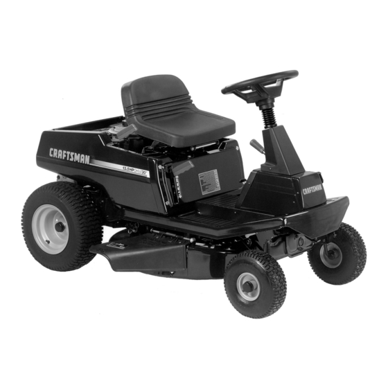
13.5 HP. ELECTRIC START
30" MOWER / MULCHER
5 SPEED
REAR ENGINE RIDER
Assembly
Operation
Customer Responsibilities
Service And Adjustment
Sears, Roebuck and Co., Hoffman Estates, IL. 60179 U.S.A.
Printed in U.S.A.
Advertisement
Table of Contents

Related Manuals for Sears 536.270212


Summary of Contents for Sears 536.270212
- Page 1 30” MOWER / MULCHER This Equipment. 5 SPEED To Call Toll Free REAR ENGINE RIDER For Service 1–800–4–REPAIR (1–800–473–7247) Assembly For Parts Operation 1–800–366–PART Customer Responsibilities (1–800–366–7278) Service And Adjustment F–000614J Sears, Roebuck and Co., Hoffman Estates, IL. 60179 U.S.A. Printed in U.S.A.
-
Page 2: Table Of Contents
For two (2) years from the date of purchase, if this Craftsman Equipment is maintained, lubricated and tuned up according to the instructions in the owner’s manual, Sears will repair or replace free of charge any parts found to be defective in material or workmanship. -
Page 3: Customer Responsibilities
Congratulations on your purchase of a Sears Rider. It has been NOTE: This unit is equipped with an internal combustion engine and designed, engineered and manufactured to give you the best must not be used on or near any unimproved forest–covered, possible dependability and performance. -
Page 4: Safety Rules
OWNER’S INFORMATION SAFETY RULES Safe Operation Practices for Ride–on Mowers WARNING: This cutting machine is capable of amputating hands and feet and throwing objects. Failure to observe the following safety instructions could result in serious injury or death. I. General operation Read, understand and follow all instructions in the Instruction Book, on the machine, the engine and with any attachments before starting. -
Page 5: Responsibility Of The Owner
OWNER’S INFORMATION III. Children Tragic accidents can occur if the operator is not alert to the presence of children. Children are often attracted to the machine and the mowing activity. NEVER assume that children will remain where you last saw them. Keep children out of the mowing area and in the watchful care of another responsible adult. -
Page 6: Accessories And Attachments
PERFORMANCE Sears offers a wide variety of attachments that fit your riding mower. Many of these are listed below with brief explanations of how they can help you. This list was current at the time of publication; however, it may change in future years – more attachments may be added, changes may be mode in these attachments, or some may no longer be available or fit your model. -
Page 7: Assembly
ASSEMBLY PREPARATION The unit is completely assembled except for the items shown in Figure 1. These items are in the carton along with a parts bag. The Seat parts bag contains the fasteners needed to complete the assembly of the unit. Find and remove these items. Do not discard any parts or material until the unit is assembled. -
Page 8: Maintenance Free Battery
ASSEMBLY MAINTENANCE FREE BATTERY Check the battery date on top of the battery (Figure 2). The battery date tells if the battery must be charged. If the battery is put into service after the battery date, the battery must be charged. See “How To Charge The Maintenance Free Battery”. -
Page 9: How To Assemble The Steering Wheel
ASSEMBLY HOW TO ASSEMBLE THE STEERING WHEEL Use the fasteners shown below to install the steering wheel. The NOTE: Make sure the steering wheel is tight. If the steering fasteners are shown at full size. wheel is loose, tighten the fasteners. Î... -
Page 10: How To Install The Seat
ASSEMBLY HOW TO INSTALL THE SEAT Use the fasteners shown below to install the seat. The fasteners are WARNING: For correct and safe operation of the unit, shown at full size. fasten the connector to the wire harness. If the connector is not attached, the engine will stop when the attachment clutch is engaged. -
Page 11: Operation
The operation of any lawn mower can result in foreign objects thrown in the eyes, which can result in severe eye damage. Always wear safety glasses or eye shields before starting your lawn mower and while mowing. We recom- mend the Wide Vision Safety Mask for over the spectacles or standard safety glasses, available at Sears Retail or Catalog Stores. -
Page 12: How To Use The Throttle Control
OPERATION HOW TO USE THE THROTTLE CONTROL Move the attachment clutch to the DISENGAGE position to stop the blade(s). Before you leave the operator’s position, Use the throttle control to increase or decrease the speed of the make sure the blade(s) has stopped rotating. engine. -
Page 13: How To Set The Parking Brake
OPERATION HOW TO SET THE PARKING BRAKE Completely push the clutch/brake pedal forward. Lift the parking brake lever (Figure 9). Remove your foot from the clutch/brake pedal and then release the parking brake lever. Make sure the parking brake will hold Parking Brake the unit. -
Page 14: How To Operate With The Mower Housing
OPERATION HOW TO OPERATE WITH THE MOWER HOUSING WARNING: The deflector is a safety device. Do not re- Move the shift lever to one of the speed settings. move the deflector. The deflector forces the dis- NOTE: When you mow in heavy grass or mow with a charged material toward the ground. -
Page 15: Before Starting The Engine
OPERATION BEFORE STARTING THE ENGINE CAUTION: A mixture of alcohol (ethanol or methanol) and gasoline (called gasohol), will attract moisture and cause acid CHECK THE OIL deposits during storage. While the unit is in storage, the acids in the fuel can damage the fuel system. NOTE: The engine was shipped from the factory filled with SAE 30 weight oil. -
Page 16: How To Change The Mulcher Plate
OPERATION HOW TO CHANGE THE MULCHER PLATE Lift the mulcher plate away from the mower housing (Figure 12). WARNING: To prevent the engine from starting, dis- connect the wire from the spark plug. Make sure the attachment clutch is in the DISENGAGE position. The mulcher plate lets you mulch the grass for a clean, fine cut. -
Page 17: Operating Tips
OPERATION OPERATING TIPS Check the attachment clutch for correct adjustment. For the Before you make an inspection, adjustment (except for the car- blade(s) to disengage correctly, the adjustment must be cor- buretor) or repair, make sure the wire from the spark plug is dis- rect. -
Page 18: Customer Responsibilities
CUSTOMER RESPONSIBILITIES MAINTENANCE CHART FIRST EVERY EVERY EVERY EACH BEFORE PROCEDURE HOURS HOURS HOURS HOURS STORAGE Blade, Inspect and Sharpen Attachment Clutch, Check Brake, Check Clutch, Check Tires, Check Battery, Check and Charge Battery, Clean Lubrication Oil, Check Cooling System, Clean Oil, Change Air Filter, Clean Muffler, Check... -
Page 19: How To Remove And Install The Blade
CUSTOMER RESPONSIBILITIES INSPECT BLADE Tighten the nut that holds the blade to a torque of 35 foot pounds (47,5 N–m). WARNING: Before you inspect or remove the blade, 10. Install the mower housing. See “How To Install The Mower disconnect the wire to the spark plug. If the blade hits an object, stop the engine. -
Page 20: How To Adjust The Attachment Clutch
CUSTOMER RESPONSIBILITIES HOW TO ADJUST THE ATTACHMENT CLUTCH Attachment Clutch Engage Postion WARNING: To prevent an injury, the attachment clutch must operate correctly. Stop the engine. Disconnect the wire from the spark plug. Before you adjust the attachment clutch, check and level the mower housing. -
Page 21: How To Check And Adjust The Drive Brake
CUSTOMER RESPONSIBILITIES HOW TO CHECK AND ADJUST THE DRIVE BRAKE HOW TO CHECK AND ADJUST THE CLUTCH Before you adjust the brake, check the clutch adjustment. See If the motion drive belt is loose, the clutch will slip when; (1) going the instructions on “How To Check And Adjust The Clutch”. -
Page 22: How To Remove The Side Panel
CUSTOMER RESPONSIBILITIES HOW TO REMOVE THE SIDE PANEL Remove the black cable from the negative (–) terminal (Figure 23). To help service the engine or the battery, each side panel can be easily removed. Remove the red cable from the positive (+) terminal. Remove the screws that hold the back of the side panel Remove the battery clamp from the battery. -
Page 23: Where To Lubricate
CUSTOMER RESPONSIBILITIES WHERE TO LUBRICATE Lubricate the areas shown with engine oil. Apply grease with a brush to the areas shown. NOTE: Apply grease to the steering gear assembly. CAUTION: If the unit is operated in dry areas that have sand, use a dry graphite spray to lubricate the unit. -
Page 24: How To Check The Oil
CUSTOMER RESPONSIBILITIES ENGINE HOW TO CHANGE THE OIL NOTE: Do not drain the oil from a cold engine. Before you drain the oil, let the engine run for several minutes. Make sure you do HOW TO CHECK THE OIL not get oil on the belts. NOTE: Do not check the level of the oil while the engine runs. -
Page 25: How To Clean The Air Filters
CUSTOMER RESPONSIBILITIES HOW TO CLEAN THE AIR FILTERS Some engines have two filters, an outer foam filter around an inner 11. Assemble the air filters with the two nuts. paper filter. Clean the air filters every 50 hours. If you operate in 12. -
Page 26: Service And Adjustment
SERVICE AND ADJUSTMENT HOW TO ADJUST THE THROTTLE CONTROL CHOKE For the best engine performance, set the throttle control as follows. FAST Move the throttle control to the FAST position (Figure 28). Throttle Control Loosen the clamp screw so that the throttle control cable can move in the cable clamp (Figure 29). -
Page 27: How To Remove The Mower Housing
SERVICE AND ADJUSTMENT HOW TO REMOVE THE MOWER HOUSING HOW TO INSTALL THE MOWER HOUSING Completely turn the steering wheel to the right. Push the mower Move the lift lever to the middle position. housing under the left side of the unit. Move the attachment clutch to the DISENGAGE position Slide the mower drive belt between the stack pulley and the (Figure 30). -
Page 28: How To Level The Mower Housing
SERVICE AND ADJUSTMENT HOW TO LEVEL THE MOWER HOUSING Disconnect one or both adjuster plates from the hangers (Figure 32). If the mower housing is level, the blade will cut easier and the lawn The higher number holes in the adjuster plates will raise the will look better. -
Page 29: How To Replace The Motion Drive Belt
SERVICE AND ADJUSTMENT HOW TO REPLACE THE MOTION DRIVE BELT Slide the motion drive belt between the belt retainer and idler REMOVAL pulley. Make sure the flat side of the motion drive belt is against Remove the mower housing. See the instructions on “How To the idler pulley. -
Page 30: How To Replace The Mower Drive Belt
SERVICE AND ADJUSTMENT HOW TO REPLACE THE MOWER DRIVE BELT REMOVAL Pull the belt retainer away from the idler pulley. Put the mower drive belt around the idler pulley. Move the lift lever to the lowest position. Make sure the mower drive belt is inside all the belt guides. Slide the mower drive belt between the stack pulley and the Also make sure the mower drive belt is not twisted. -
Page 31: How To Replace The Fuse
SERVICE AND ADJUSTMENT HOW TO REPLACE THE FUSE If the fuse is blown, the engine will not start. The location of the fuse is next to the battery. Remove the fuse and replace with a 15 amp. 15 amp automotive fuse (Figure 38). Automotive Fuse Figure 38 HOW TO SET THE CUTTING HEIGHT... -
Page 32: Storage (Over 30 Days)
SERVICE AND ADJUSTMENT STORAGE (over 30 days) prevent engine problems with the fuel system, empty the fuel system before storage of 30 days or longer. At the end of each year, prepare the unit for storage as follows. NOTE: Fuel stabilizer (like STA–BIL) is an acceptable alternative in reducing the formation of fuel gum in the fuel tank GENERAL INSPECTION and the gasoline storage container. -
Page 33: Trouble Shooting Chart
TROUBLE SHOOTING CHART PROBLEM: The engine will not start. PROBLEM: A hot engine causes a decrease in power. Follow the steps, “How To Start The Engine” in this book. Clean the air screen. Electric–Start Models: Clean the battery terminals. Tighten the Check the oil. -
Page 34: Slope Guide
F–000614J... -
Page 35: Index
INDEX Type, 15 Operation Drive Brake Adjustments Attachment Clutch, 11, 12 Adjust, 21 Attachment Clutch, 20 Clutch / Brake Pedal, 11 Check, 21 Clutch, 21 Emergency Start, 15 Drive Brake, 21 Ignition Switch, 11 Mower Housing Lift Lever, 11, 13 Cutting Height, 31 Location Of Controls, 11 Engine... - Page 36 MODEL 536.270212 REPAIR PARTS BODY CHASSIS 16 35 F–000614J...
-
Page 37: Repair Parts
MODEL 536.270212 REPAIR PARTS BODY CHASSIS Description Part No. Mfg. No. Description Part No. Mfg. No. Seat 92387 Bracket, Cover Mounting 56233E700 Hinge, Seat 56516E700 Screw 26x250 Retainer 28x64 Support, Body 56122E700 Lockwasher STD551131 18x16 Bolt, Shoulder 9x29 Bolt, Hex... - Page 38 MODEL 536.270212 REPAIR PARTS MOTION DRIVE 60 61 F–000614J...
- Page 39 MODEL 536.270212 REPAIR PARTS MOTION DRIVE Description Part No. Mfg. No. Description Part No. Mfg. No. Locknut, Flange STD541431 15x88 Link, Parking Brake 56565Z Guide, Belt 93349 Spring, Extension 165x107 Shifter Assembly 56610E701 Pin, Cotter STD560907 30x50 Locknut, Flange STD541437...
- Page 40 MODEL 536.270212 REPAIR PARTS STEERING F–000614J...
- Page 41 MODEL 536.270212 REPAIR PARTS STEERING Description Part No. Mfg. No. Steering Wheel 54783 Bellows, Steering Post 54789 Bolt, Hex STD523115 1x10² Locknut, Flange STD541431 15x88 Post, Steering 56417C Nut, Hex STD541531 15x90 Bolt, Carriage STD533107 2x64 Screw 26x249 Plate, Left Suspension...
-
Page 42: Mower Housing Suspension
MODEL 536.270212 REPAIR PARTS MOWER HOUSING SUSPENSION F–000614J... - Page 43 MODEL 536.270212 REPAIR PARTS MOWER HOUSING SUSPENSION Description Part No. Mfg. No. Locknut, Flange STD541437 15x84 Washer STD551037 17x53 Pin, Cotter STD560907 30x20 Screw 26x249 Bolt, Shoulder 9x9Z Nut, Adjusting 21920 Grip, Blade Control 92698 Lever Assembly, Lift 56031E701 Grip, Lift Lever...
-
Page 44: Mower Housing
MODEL 536.270212 REPAIR PARTS MOWER HOUSING Î Î Î Î Î Î F–000614J... - Page 45 MODEL 536.270212 REPAIR PARTS MOWER HOUSING Description Part No. Mfg. No. Description Part No. Mfg. No. Belt, Mower Drive 37x57 Spring, Torsional 166x4 Pulley, Splined 91951 Push On Cap 28x23 Lockwasher 18x33 21197Z Locknut, Hex 15x100 Hinge, Chute Deflector 56213E701...
- Page 46 MODEL 536.270212 REPAIR PARTS ELECTRICAL SYSTEM Î F–000614J...
-
Page 47: Electrical System
MODEL 536.270212 REPAIR PARTS ELECTRICAL SYSTEM Description Part No. Mfg. No. Switch, Seat Sensor 91031 Nut, Keps STD541425 15x66 Bolt, Carriage STD533125 2x82 Battery (Type U1-L5) 92196 Cable, Battery Ground (Black) 24x3 Screw 26x249 Cable, Positive Battery (Red) 24x24 Cap, Ignition Switch... - Page 48 MODEL 536.270212 REPAIR PARTS 5 SPEED TRANSAXLE DANA MODEL: 4450–1 F–000614J...
- Page 49 MODEL 536.270212 REPAIR PARTS 5 SPEED TRANSAXLE DANA MODEL: 4450–1 Description Part No. Description Part No. Housing, Upper 3975 Washer, Plain .505 x .942 x .010 *3886 Screw, Tapping 1/4-20 x .734 (14 req.) 1919 Washer, Plain .505 x .942 x .015 *3887 Ball, Detent (2 req.)
- Page 50 MODEL 536.270212 ENGINE 143.981300 REPAIR PARTS F–000614J...
- Page 51 MODEL 536.270212 ENGINE 143.981300 REPAIR PARTS F–000614J...
- Page 52 MODEL 536.270212 ENGINE 143.981300 REPAIR PARTS Key No. Description Part No. Key No. Description Part No. Cylinder (Incl. 2 & 20) 35943A Ground, Terminal 33356 Dowel Pin 27652 Mounting Flange Gasket 35317 Washer 28277 Mounting Flange 35711A (Incl. 72, 75 & 80)
- Page 53 MODEL 536.270212 ENGINE 143.981300 REPAIR PARTS Lock Nut, 5/16–24 650947 Cylinder Head Cover 35959 Push Rod 35951 Screw, 5/16–18 x 1–1/4” 650876 Rocker Arm Cover Gasket 35952 Exhaust Manifold Gasket 35762 Rocker Arm Housing 35953A Exhaust Manifold 36839 Screw, Torx T–30, 1/4–20 x 1/2”...
- Page 54 MODEL 536.270212 ENGINE 143.981300 REPAIR PARTS Key No. Description Part No. Key No. Description Part No. Carburetor (Incl.lA,184 of Engine 640115 Welch Plug, Idle Mixture Well 630748 Parts List) Welch Plug, Atmospheric Vent 631027 Throttle Shaft & Lever Assembly 632649...
- Page 55 MODEL 536.270212 ENGINE 143.981300 REPAIR PARTS ELECTRIC STARTER Description Part No. Electric Starter 36680 Dust Cover 33451 Retainer Ring 33842 Spring Retainer 33430 Anti–drift Spring 33854 Gear 33432 Nut & Retainer 35893 Lock Nut 33450 Drive End Cap Assly. 35894...
-
Page 56: Electrical Schematic
MODEL 536.270212 REPAIR PARTS ELECTRICAL SCHEMATIC BATTERY BLACK – STARTER SOLENOID FUSE 15 AMP ORANGE PARK BRAKE ATTACHMENT IGNITION INTERLOCK SWITCH INTERLOCK SWITCH SWITCH (BRAKE ENGAGED) (DISENGAGED) ORANGE ORANGE ORANGE BLACK YELLOW SOLID STATE IGNITION SPARK PLUG SEAT SWITCH YELLOW (UNOCCUPIED) N.C. - Page 57 NOTES F–000614J...
- Page 58 NOTES F–000614J...
- Page 59 NOTES F–000614J...
- Page 60 Your Sears merchandise has added value when you consider Sears has service units nationwide staffed with Sears trained technicians. Sears technicians have the necessary (1–800–366–7278) parts, tools and equipment to meet the Sears pledge, “We Service What We Sell”. F–000614J Sears, Roebuck and Co., Hoffman Estates, IL. 60179 U.S.A.