Table of Contents
Advertisement
Advertisement
Table of Contents

Related Manuals for Kemppi MasterTig 3500


Summary of Contents for Kemppi MasterTig 3500
- Page 1 Service manual Ver. 1.0 1400 2800 1500 3500 2200 1500 2200 2800 3500...
-
Page 2: Table Of Contents
Contents General Technical data, switches and connectors Mastertig function panels 7-10 Operating principle IGBT gate pulse (2800/3500) Voltage over the lower IGBT (2800/3500) Voltage after the secondary diodes (2800/3500) IGBTgate pulse (1400-2200) Voltage over the lower IGBT (1400-2200) Voltage after the secondary diodes (1400-2200) Troubleshooting 18-20 Power source control card A001 block diagram... -
Page 3: General
General Master- and Mastertig-power sources are MMA and TIG power sources designed for demanding professional use. Master- and Mastertig-power sources are IGBT-inverters, controlled by PWM-principle. Operation frequency is approx. 18 kHz. 5 power source sizes are available; 1~ 140 A, 1~ 150 A, 3~ 220 A, 3~ 280 A and 3~ 350 A Technical data, switches and connectors Master 1400 1 Main switch S001 and welding current connectors... - Page 4 Master 1500 1 Main switch S001, welding current connectors and dynamics adjustment 2 Overheat protection signal lamp 3 Remote controller connection 4 Local / remote control 5 Current adjustment potentiometer 220V –10%….240V +6% Supply voltage 1∼,50/60 Hz 150 A / 6,6 kVA Connection power 20% ED 105 A / 4,4 kVA...
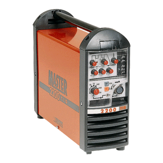
- Page 5 Master 2200 1 Main switch S001, welding current connections and dynamics adjustment 2 I/0-signal lamp 3 Remote controller connecyor 4 Overheat protection signal lamp 5 Remote / local control selection 6 Current adjustment potentiometer 380V –10%….415V +6% Supply voltage 3∼,50/60 Hz 220 A / 8,4 kVA Connection power 25% ED...
- Page 6 Master 2800 and 3500 1 Main switch S001 and welding current connectors 2 I/0-signal lamp 3 Overheat protection signal lamp 4 Dynamics adjustment 5 Current adjustment potentiometer 6 local / remote control 7 Remote controller connector 380V –10%….415V +6% 380V –10%….415V +6% Supply voltage 3∼,50/60 Hz 280 A / 11,5 kVA 350 A / 15,0 kVA...
-
Page 7: Mastertig Function Panels
Mastertig 1500 and 2200 1 Main switch S001, dynamics adjustment and welding current connections 2 Current adjustment potentiometer 3 Overheat protection signal lamp 4 Local / remote control selection 5 Remote controller connector Pulse panel Pregas time Pause current Postgas time 2T/4T-selection Ignition method and process selection Continous / pulse... - Page 8 Minilog-panel Pause current Pulse frequency Post gas time 2T/4T-selection Ignition method and process selection Downslope time Minilog-operation selection, minilog-current adjustment Minilog-functions not in use Pulse welding selection and Current upslope time, pulse ratio adjustment continous welding Continous welding selection...
- Page 9 Mastertig 2800 and 3500 1 Main switch S001 and welding current connectors 2 I/0-signal lamp 3 Overheat protection signal lamp 4 Dynamics adjustment 5 Current adjustment potentiometer 6 Local / remote control selection 7 Remote controller connector Pulse panel Pregas time Postgas time Pause current 2T/4T-selection...
- Page 10 Minilog-panel Pause current Pulse frequency Postgas time 2T/4T-selection Ignition method and process selection Downslope Minilog-function selection, minilog current adjustment Minilog-functions not in use Pulse welding selection and Current upslope time adj. pulse ratio adjustment continous welding Continous welding selection...
-
Page 11: Operating Principle
Operation principle The power stage in Master- and Mastertig- power sources is a traditional half-bridge, where the intermediate circuit´s dc-voltage is halved by load capacitors C2 and C3. IGBT-transistors are used as power switches. When both IGBTs are not conductive, no power is transferred. When the upper IGBT (V2) is conductive, there is positive voltage in the main transformer´s (T1) primary, and when the lower IGBT (V3) is conductive there is negative voltage in the main transformer´s (T1) primary. -
Page 12: Igbt Gate Pulse (2800/3500)
IGBT gate pulse (Master / Mastertig 2800/3500) IGBT gate pulse with minimum power (2800/3500). Inverter operating frequency approx. 19 kHz (measuring point A). IGBT gate pulse with maximum power (2800/3500). Inverter operating frequency approx. 19 kHz (measuring point A). -
Page 13: Voltage Over The Lower Igbt (2800/3500)
Voltage over the lower IGBT (Master / Mastertig 2800/3500) Voltage over the lower IGBT with minimum power (2800/3500). Inverter operating frequency approx. 19 kHz (measuring point B). Voltage over the lower IGBT with maximum power (2800/3500). Inverter operating frequency approx. 19 kHz (measuring point B). -
Page 14: Voltage After The Secondary Diodes (2800/3500)
Voltage after the secondary diodes (Master / Mastertig 2800/3500) Voltage over the secondary diodes with minimum power(2800/3500). Frequency is approx. 38 kHz (measuring point C). Voltage over the secondary diodes with maximum power (2800/3500). Frequency approx. 38 kHz (measuring point C). -
Page 15: Igbtgate Pulse (1400-2200)
IGBT gate pulse (Master / Mastertig 1400/1500/2200) IGBT gate pulse with minimum power (1400/1500/2200). Inverter operating frequency approx. 18 kHz (measuring point D). IGBT gate pulse with maximum power (1400/1500/2200). NOTE. Inverter operating frequency approx. 25 kHz (measuring point D). -
Page 16: Voltage Over The Lower Igbt (1400-2200)
Voltage over the lower IGBT (Master / Mastertig 1400/1500/2200) Master 1400/1500 Master 2200 Lower IGBT control (Gate pulse; measuring point D / Voltage over the lower IGBT; measuring point E). -
Page 17: Voltage After The Secondary Diodes (1400-2200)
Voltage after the secondary diodes (Master / Mastertig 1400/1500/2200) Master 2200 Master 1400/1500 Voltage after the secondary diodes (measuring point F) and lower IGBT gate pulse (measuring point D). -
Page 18: Troubleshooting
Troubleshooting The machine may be repaired only by an authorized and licensed technician or workshop! First do a visual check to find the possible loose connectors, broken wires or signs of overheating. Also check the condition of the welding cables, welding guns / torches and all consumable parts. Troubleshooting diagram DISTURBANCE POSSIBLE CAUSE... - Page 19 DISTURBANCE POSSIBLE CAUSE REMEDY The power source will not deliver A net fuse has blown Check the net fuses full power Faulty supply cable Check the supply cable condition Faulty main switch Check the main switch condition Faulty primary side power semi- Check the primary rectifier and conductor IGBT-module...
- Page 20 A002 and A003 (see page 23) Faulty control card A002 Replace control card A002 (see pages 28 and 29) Mastertig 3500 W-cooling unit Faulty pressure switch Check the pressure switch doesn´t stay on, when operated by it´s start switch...
-
Page 21: Power Source Control Card A001 Block Diagram
Control card A001 block diagram Set value circuit Controller and Control to IGBT Gate buffers Current instruction development MMA ignition Fan control TIG/MMA Locking Overheat protection dynamics Power supply adjustment Net voltage watch Actual current value Current information to TIG AV~40 The functions of power source´s control card A001 are built around the PWM-controller SG 3526. -
Page 22: Mastertig-Power Source´s Tig-Section´s Functions
Mastertig-power source´s TIG-section The TIG-section provides these programmatic functions: • Pre- and postgas timings • Up- and downslopes • Tacking automatics • Switch functions (2T/4T) • Pulse functions • Pulse led control • Ignition spark control and watch • Contact ignition control and watch •... -
Page 23: Signals Between Control Cards A001 And A002
Signals between control cards A001 and A002 (Mastertig 1500-3500) Current set value from power source (0,5…5 Vdc) Current set value to power source (0,5…5 Vdc) Output voltage information from power source (OCV on MMA is approx. 75 Vdc) MMA/TIG-selection (TIG = 4,5 Vdc, MMA = 0 V) 26 Vac from power source 26 Vac from power source 16 Vac from power source... -
Page 24: Control Card A001 Layout (1400/1500)
Control card A001 layout (Master / Mastertig 1500) Scratch-TIG OCV approx. + 80 V OCV approx.. + 40 V Maximum current MMA ignition current Minimum current Inverter frequency Set value min. (TIG) Control card A001 layout (Master / Mastertig 2000/2200) Scratch-TIG Net voltage 3∼... -
Page 25: Control Card A001 Layout (2800/3500)
Control card A001 layout (Master / Mastertig 2800/3500) Scratch-TIG Net voltage 3∼ 400 V Net voltage 3∼ 460 V Net voltage 3∼ 460 V Net voltage 3∼ 400 V OCV approx. + 80 V OCV approx. + 40 V Maximum current MMA ignition current Minimum current Inverter frequency... -
Page 26: Control Card A002 Layout (1500/2200)
Control card A002 layout (Master / Mastertig 1500/2200) JUMPERS When a jumper is disconnected: X12 Tacking automatics goes off X13 Downslope time becomes non-linear, downslope times become longer with low currents X14 Postgas becomes independent from set value, and adjustable linearly adjustable between 0 - 120s X15 Downslope will go all the way to the minimum, and won´t be cut-off at 15 % level of the welding current... -
Page 27: Control Card A004 Layout (2800/3500)
Control card A004 layout (Master / Mastertig 2800/3500) F1 1,6AT Power (Spark) R13 Voltage (Spark) Control card A001 functional testing Control card power supply ? (2 x 13 Vac) Temperature watch PTC ? IGBT gate pulses Set value information ? Control card A001 develops the IGBT gate pulses. -
Page 28: Control Card A002 Operation Check
Control card A002 functional testing Current set value to power source (0,5…5 Vdc) Current set value to power source (0,5…5 Vdc) Output voltage from power source (OCV on MMA 75 Vdc) MMA/TIG-selection (TIG = 4,5 Vdc, MMA = 0 V) 26 Vac from power source 26 Vac from power source 16 Vdc from power source... - Page 29 A=Pin 2 voltage Pulse ratio approx. 10 %, pause current 40 % and cycle time 1,5 s (0,7 Hz) B= Pin 1 voltage Set value information from control card A001´s set value circuit A= Pin 2 voltage Pulse ratio approx. 50 %, pause current 40 % and cycle time approx.
-
Page 30: Control Card A004 Operation Check
Control card A004 functional testing (Mastertig 2800/3500) 24 Vac Spark generator on/off Start switch detection X6/3 (A004) Mastertig 2800/3500 control card A004 generates the ignition spark for TIG and it also reads the torchswitch states. The torch switch is separated from other electronics on the transformer, because the voltage inducted to the switch lines is almost full spark voltage (approx. -
Page 31: Notes
Notes...