Table of Contents
Advertisement
Advertisement
Table of Contents

Related Manuals for Husky Altanium Neo2


Summary of Contents for Husky Altanium Neo2
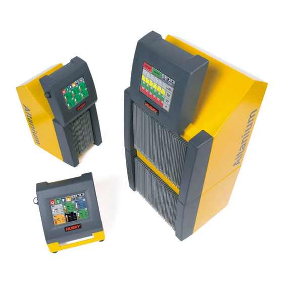
- Page 1 Altanium Neo2 User Guide Original Instructions...
- Page 2 Husky® product or service names or logos referenced in these materials are trademarks of Husky Injection Molding Systems Ltd. and may be used by certain of its affiliated companies under license.
-
Page 3: General Information
General Information Husky Technical Support Husky Technical Support is a service provided to all of our customers. Our goal is to provide quick and accurate responses to all customers entitled to our service. When you contact Support, your case will be immediately logged. Your support issue will be tracked from the time it is opened until a resolution is provided. -
Page 4: Husky Regional Service And Sales Offices
1.4 — September 2015 Altanium Neo2 Husky Regional Service and Sales Offices... -
Page 5: Table Of Contents
Husky Regional Service and Sales Offices ........ - Page 6 1.4 — September 2015 Altanium Neo2 Changing the Language Display ..........21 Supply Voltage Screen .
- Page 7 User Guide v 1.4 — September 2015 Table of Contents 7.3.7 Changing the Automatic Manual Control (AMC) Setting ....49 7.3.8 Changing the Power Limit Setting ........49 7.3.9 Changing the Earth Leakage Setting .
- Page 8 1.4 — September 2015 Altanium Neo2 9.2.4 Setting the Global Power Limit..........67 9.2.5...
- Page 9 User Guide v 1.4 — September 2015 Table of Contents 11.2.2 Integrated I/O Option (Outputs) ......... . 86 11.2.3 Input and Output Option Cable Pin-Out Description .
- Page 10 1.4 — September 2015 Altanium Neo2...
-
Page 11: Chapter 1 Introduction
User Guide v 1.4 — September 2015 Introduction Chapter 1 Introduction This User Guide includes general warnings and cautions to avoid injury to personnel and damage to the system. These warnings and cautions are not intended to be, nor are they all- inclusive to every condition or application that may occur during operation. -
Page 12: Safety Signs
Follow all warnings and instructions marked on the system. • Unless specifically explained in this manual or directed by Husky, do not attempt to repair the system. Doing so could result in damage to the system, or serious personal injury. -
Page 13: Purpose Of The Equipment
Husky controllers are designed to control the process temperature for injection molding applications only. Contact your nearest Husky Regional Service and Sales office if you plan to use a Husky product for anything other than its intended use. Restrictions of Use Husky injection molding equipment must never be: •... - Page 14 Follow all warnings and instructions marked on the system. • Unless specifically explained in this manual or directed by Husky, do not attempt to repair the system. Doing so could result in damage to the system, or serious personal injury.
-
Page 15: Input Wiring (Conventional)
User Guide v 1.4 — September 2015 Introduction Input Wiring (Conventional) The following table summarizes the wiring conventions used. Description Wire Color Neutral Blue Earth/Ground Green Green/Yellow Line Black Black Line Brown Line Gray White DANGER! Electrocution and/or mechanical hazard - risk of death or serious injury and possible damage to the equipment. - Page 16 1.4 — September 2015 Altanium Neo2 Altanium Webbed Straps Rated Lifting Device Ratchet Strap Controller 2903 kg (6400 lb) (Lifting Ability) Single Stack Two, 2.44 m x 25.4 mm One, 1.52 m (5 ft) 227 kg (500 lb) (8 ft x 1 in.) Double Stack Two, 3.66 m x 25.4 mm...
- Page 17 User Guide v 1.4 — September 2015 Introduction Figure 1-2 Positioning Straps b. Make sure the straps are not pinching or crushing any cables attached to the controller. Figure 1-3 Checking Cables Use the lifting device to apply enough upward force on the straps to remove the slack, but do not lift the controller at this time.
- Page 18 1.4 — September 2015 Altanium Neo2 Figure 1-4 Protecting the Controller Finish Tighten the ratchet strap. Use the lifting device to slowly lift the controller off the ground a few inches. Check the webbed and ratchet straps to ensure the controller will not tip.
-
Page 19: Chapter 2 Hot Runner Temperature Control
User Guide v 1.4 — September 2015 Hot Runner Temperature Control Chapter 2 Hot Runner Temperature Control This guide is designed to make sure that you receive the maximum possible benefit from the use of the Altanium Hot Runner Control Systems. The Altanium controllers were designed as a processor's tool for hot runner molding. -
Page 20: Closed Loop Control
1.4 — September 2015 Altanium Neo2 2.1.2 Closed Loop Control With the aid of a thermocouple, it is possible to control the actual temperature inside the mold. The Altanium controller can only control the temperature at the point at which the temperature sensor is positioned. -
Page 21: Heating Elements
User Guide v 1.4 — September 2015 Hot Runner Temperature Control In either control method, the Altanium controller recalculates the power output requirements for the entire system every 8 milliseconds to obtain the maximum control resolution. By combining either of the above control methods with the Active Reasoning Technology (ART) control algorithm, it is possible to achieve accurate temperature control with the expectation of control accuracy of ±... -
Page 22: Thermocouple Types And Color Codes
1.4 — September 2015 Altanium Neo2 Ohm's Law says: Amps = Watts / Volts Amps = Volts / Resistance Resistance = Volts / Amps Watts = Volts x Amps Example: If the resistance is 12.5 ohms, and the input voltage is 240 volts, you would divide 240 by 12.5 to calculate the maximum amperage draw on that heating element:... -
Page 23: Chapter 3 Connecting The System To The Mold
User Guide v 1.4 — September 2015 Connecting the System to the Mold Chapter 3 Connecting the System to the Mold This chapter outlines various checks to make prior to starting up the system. Prior to Start Up • Check that the system is completely disconnected from the power source. •... -
Page 24: Start Up Procedure Checklist
1.4 — September 2015 Altanium Neo2 Start Up Procedure Checklist Item Step Connect power/thermocouple cables between the mold and controller (if required). Connect option cables (if required). Connect the controller to the power source. Switch the controller ON. Load a mold setup. -
Page 25: Chapter 4 Neo2 Operator Interface
User Guide v 1.4 — September 2015 Neo2 Operator Interface Chapter 4 Neo2 Operator Interface This section describes the fundamental operating procedures of the Altanium/Neo2 hot runner process controller. The interface between the user and the Altanium/Neo2 is a color LCD Display with a Touch Screen. - Page 26 1.4 — September 2015 Altanium Neo2 Figure 4-1 Home Screen The STOP, START, STANDBY and BOOST function buttons are located in the upper left hand portion of the LCD display. Button Description STOP button - Turns power OFF to all zones, regardless of system condition.The button will appear darker when in the STOP mode.
-
Page 27: Operator Interface Modes
User Guide v 1.4 — September 2015 Neo2 Operator Interface Button Description Zone Data Layout - Used to toggle between 6, 12, 24 and 48 zone screen layouts. Home - Used to return to the Home screen SPEAKER - used to clear and reset Alarm and Abort errors. Date/Time - Displays current date and time on the system. -
Page 28: Usb Port
1.4 — September 2015 Altanium Neo2 Figure 4-2 System Setup Screen - Basic Mode 1. BASIC ADV button To go back to Basic mode, touch BASIC ADV. USB Port The USB port on the Neo2 is intended to be used to copy mold setup files to and from the system and to print information to a file. -
Page 29: Printing Reports To File
User Guide v 1.4 — September 2015 Neo2 Operator Interface The following warnings and restrictions should be observed when using the USB port: • Only supports USB disks that use a File Allocation Table (FAT or FAT32) format. • Only supports USB versions 2.0 and 1.1. •... - Page 30 1.4 — September 2015 Altanium Neo2 Figure 4-3 Print Screen Touch the report to print. The selected report prints to file on the USB drive. Printing Reports to File...
-
Page 31: Changing The Language Display
User Guide v 1.4 — September 2015 Neo2 Operator Interface Changing the Language Display Neo2 allows the operator to select the language displayed on screen. To change the language: On the Home screen, touch Language. The Language screen appears and displays available options. -
Page 32: Viewing The Supply Voltage
1.4 — September 2015 Altanium Neo2 4.6.1 Viewing the Supply Voltage To view the Supply Voltage screen, do the following: On the Home screen, touch the Supply Voltage button. The Supply Voltage screen displays for the type of configuration selected. - Page 33 User Guide v 1.4 — September 2015 Neo2 Operator Interface Figure 4-6 Delta 3PH Supply Voltage Screen Figure 4-7 Single Phase Supply Voltage Screen Viewing the Supply Voltage...
- Page 34 1.4 — September 2015 Altanium Neo2 Figure 4-8 Integrated TX Supply Voltage Screen Viewing the Supply Voltage...
-
Page 35: Chapter 5 Security
User Guide v 1.4 — September 2015 Security Chapter 5 Security The System can be configured to display the Security screen when the system is powered up (Refer to Section 9.2.7) or bypassed. If this screen is not configured to be displayed on power up, then it can be accessed from the Home Screen. -
Page 36: Entering A Password
1.4 — September 2015 Altanium Neo2 Button Description Touch this button to change the selected function to security level 1. Touch this button to change the selected function to security level 2. Entering a Password Factory set passwords; (Level 1 and 2) are shipped in a sealed envelope along with the controller. -
Page 37: Setting Security Levels For Specific Functions
User Guide v 1.4 — September 2015 Security Figure 5-3 Numerical Key Window 1. Enter Button In the numerical key window, enter the new password and then touch Enter. Passwords are limited to 10 digits. The new password will now be displayed. Setting Security Levels for Specific Functions The Neo2 security system provides different levels of security to restrict the access of users and maintains the controls and settings for the system. - Page 38 Enables the operator to copy a stored mold setup to a different location. Mold Setup File Default Enables the operator to delete the contents of a stored mold setup and return all values to Husky's default. Mold Setup Enables an operator to import or export a mold setup using a USB disk.
- Page 39 User Guide v 1.4 — September 2015 Security Feature Description Print Screen Enables an operator to access the Print screen to print data to a file and store it to a USB disk. Standby Timers Enables the operator to adjust the Standby timers in the System screen. Boost Timers Enables the operator to adjust the Boost timers in the System screen.
- Page 40 1.4 — September 2015 Altanium Neo2 Security Item Descriptions...
-
Page 41: Chapter 6 Mold Setups
User Guide v 1.4 — September 2015 Mold Setups Chapter 6 Mold Setups Depending on how the system is configured (Refer to Chapter 5–Security), touching the OK button in the Security screen will display the Mold Setup screen. In this screen allows the operator to choose from 24 individual mold setups to heat up your mold. -
Page 42: Loading A Mold Setup
1.4 — September 2015 Altanium Neo2 Loading a Mold Setup A mold setup must be loaded before the controller can heat up the mold. Loading a mold setup tells Neo2 the values for the setpoints, alarm bands, abort bands, etc. -
Page 43: Entering A Mold Name
User Guide v 1.4 — September 2015 Mold Setups Enter the mold setup name and the touch Enter. You will notice the time and date will be copied to the new location but the mold name will not. This is done so you will have some way to distinguish between the original and the copied setup. -
Page 44: Importing And Exporting Mold Setups
1.4 — September 2015 Altanium Neo2 Importing and Exporting Mold Setups The Mold Setup Import/Export screen is used to import and export mold setups to and from the system. This screen only appears if a USB disk is connected to the USB port. -
Page 45: Exporting A Mold Setup
User Guide v 1.4 — September 2015 Mold Setups 6.5.2 Exporting a Mold Setup To export a mold setup: Insert a USB disk to the USB port. On the Mold Setup Import/Export screen, touch the Mold Setup number from the INTERNAL MOLD SETUPS list to select the mold setup file you want to export. - Page 46 1.4 — September 2015 Altanium Neo2 Deleting a Mold Setup from a USB Disk...
-
Page 47: Chapter 7 Making Adjustments
User Guide v 1.4 — September 2015 Making Adjustments Chapter 7 Making Adjustments This chapter explains how to use Neo2 to monitor and modify the system. Zone Data On the Zone Data screen up to 48 heater zones are displayed on one screen. Depending on the number of zones and the zone layout selected each zone displays the Zone more or less information. -
Page 48: Zone Status
1.4 — September 2015 Altanium Neo2 7.1.1 Zone Status Color coding is used to display the status of each zone. • Grey indicates the zone is turned Off. • Black indicates the zone temperature is outside of the specified limits. - Page 49 User Guide v 1.4 — September 2015 Making Adjustments Figure 7-3 12 Zone Layout Figure 7-4 24 Zone Layout Zone Information Fields...
-
Page 50: Changing The Zone Layout
1.4 — September 2015 Altanium Neo2 Figure 7-5 48 Zone Layout 7.1.3 Changing the Zone Layout Touch the Zone Layout button to cycle through the 6 zone, 12 zone, 24 zone and 48 zone layouts. NOTE: The Zone Layout button can be used to navigate back to the Zone Data screen from any other screen in the system. -
Page 51: Adjusting Basic Parameters
User Guide v 1.4 — September 2015 Making Adjustments Adjusting Basic Parameters This section describes how to adjust the basic parameters, turn zones on and off and to set the manual boost and standby settings. 7.2.1 Changing a Setpoint Temperatures of the heaters must be specified. The default setting is 177 °C (350 °F). To change a setpoint: On the Quick Set screen, touch the zone to adjust. -
Page 52: Turning A Zone On Or Off
1.4 — September 2015 Altanium Neo2 Figure 7-7 Numerical Key Window 1. Enter Button Enter the new setpoint, and then touch Enter. The operator can also add or subtract from the current setpoint by entering the number and then touching the + or - button. For example, to add 4 degrees to the selected zones setpoint touch the 4 button followed by the + button. -
Page 53: Changing The Zone Regulation
User Guide v 1.4 — September 2015 Making Adjustments 7.2.3 Changing the Zone Regulation Each zone in Neo2 has the ability to run in one of two control modes, Automatic (closed loop) or Manual (open loop). This is referred to as zone regulation. A control mode must be specified for each zone. -
Page 54: Changing The Boost Setpoint
1.4 — September 2015 Altanium Neo2 7.2.5 Changing the Boost Setpoint It may be necessary to raise the temperatures in the mold for a period of time. Neo2 gives the operator the ability to do this by touching one button without having to change the normal setpoint. -
Page 55: Changing The Alarm Band
User Guide v 1.4 — September 2015 Making Adjustments Figure 7-8 Keyboard Window 1. Enter Button Enter the name or select one of the predefined names. A maximum of 12 characters are available. To automatically number, touch AUTO #. Using this button will save the name and automatically number the selected zones. -
Page 56: Changing The Abort Band
1.4 — September 2015 Altanium Neo2 7.3.3 Changing the Abort Band The number of degrees over or under setpoint must be specified to initial an alarm and the system to be stopped. The default setting is 28 °C (50 °F). -
Page 57: Using The Automatic Slave Function
User Guide v 1.4 — September 2015 Making Adjustments Based on the comparative data stored, the system knows which zone to slave the faulty zone to so that it continues to operate in a closed loop control mode. On the Home screen the auto-slaved zones number will switch between the slaved zone number and the master zone number. -
Page 58: Changing The Sensor Assignment
1.4 — September 2015 Altanium Neo2 7.3.5 Changing the Sensor Assignment The Sensor Assignment function allows the operator to assign any thermocouple to control any heater. This is important in the instance where thermocouples or heaters in the mold are mis-wired. -
Page 59: Changing The Automatic Manual Control (Amc) Setting
User Guide v 1.4 — September 2015 Making Adjustments 7.3.7 Changing the Automatic Manual Control (AMC) Setting If a thermocouple malfunctions during normal operation, the software can automatically apply a manual power output percentage to the heater based on the information gathered before the thermocouple failed. -
Page 60: Changing The Power Output Control Method Setting
1.4 — September 2015 Altanium Neo2 For more information on the Neo2’s advanced earth leakage system see Section 10.2. 7.3.10 Changing the Power Output Control Method Setting In hot runner process control systems there are two schools of thought in regards to how the power output should be switched to the heaters. -
Page 61: Possible Causes Of Oscillation
User Guide v 1.4 — September 2015 Making Adjustments 7.3.11.2 Possible Causes of Oscillation It is possible to set the control terms incorrectly, inducing an oscillation. The following are the most common causes: Table 7-2 Possible Causes of Oscillation Cause Description “P”... -
Page 62: Changing Pid Values
1.4 — September 2015 Altanium Neo2 7.3.12 Changing PID Values Sometimes it may be necessary to adjust the P, I or D values to better control the temperatures of the heaters in the mold. Refer to Table 7-1 for a list of typical PID values. The default settings are, “P”... -
Page 63: Control Method
User Guide v 1.4 — September 2015 Making Adjustments 7.4.3 Control Method The use of Active Reasoning Technology for control eliminates the tasks of using self-tune or “automatic” tune PID, PIDD or PPID algorithms. ART performs all of these tasks without the need for manual intervention. - Page 64 1.4 — September 2015 Altanium Neo2 NOTE: The system must be in run mode before a zone can be Re-ARTed. To ART a zone: On the Quick Set screen, touch the zone to ART. To select more than one zone, touch the additional zones and they will be selected.
-
Page 65: Chapter 8 Mold Diagnostics
User Guide v 1.4 — September 2015 Mold Diagnostics Chapter 8 Mold Diagnostics Throughout the history of hot runner molding, diagnosing problems in the mold has been a tedious, painstaking job. If done incorrectly or completely ignored, poor diagnostics result in a high probability of failure when the mold is placed into the machine. -
Page 66: Running A Mold Test
1.4 — September 2015 Altanium Neo2 Function Button Description Zone Displays the zone number and the test/result status. • Grey - Zone is turned off or not selected for testing. • Yellow - Zone is being tested or is selected for testing. -
Page 67: Setting The Delay Time
User Guide v 1.4 — September 2015 Mold Diagnostics Touch the zone or zone to test. 10. On the Mold Test screen, touch RUN TEST and the diagnostics test will begin. The test can be stopped at any time by touching STOP TEST. 8.1.2 Setting the Delay Time Neo2 can wait for a certain period of time before moving on to test the next zone. -
Page 68: Test Results Display
1.4 — September 2015 Altanium Neo2 Function Button Description REWIRE During the test, if the Neo2 finds any thermocouples wired incorrectly, touch this button, acknowledge to confirmation dialog box to rewire the thermocouples to the correct location. AMP, VOLT, WATT, OHM. -
Page 69: Saving Test Data For Future Reference
User Guide v 1.4 — September 2015 Mold Diagnostics 8.2.2 Saving Test Data for Future Reference The test results of a mold can be saved to compare them to another test at a later date. To do this they are saved to the internal memory of the Neo2. NOTE: Each mold setup can store its own set of saved Test data. - Page 70 1.4 — September 2015 Altanium Neo2 To see what the wattage would be at 240 volts: • Touch 240V and the adjusted wattage is displayed based on 240 VAC. Viewing Amps, Volts, Watts and Ohms Data...
-
Page 71: Chapter 9 System Setup And Customization
9.1.1 System Serial Number Each Neo2 has a unique serial number assigned to it before it leaves the factory. In the event the operator needs to contact Husky, they may ask for this number. Only Husky personnel can change this number. -
Page 72: Software Release Number
Located in the center of the screen is the Neo2 Software Release Number, Build Number and the USB Controller version. In the event the operator needs to contact Husky for service, the technician may ask for these numbers. This is not a button and touching it will do nothing. -
Page 73: Changing The Date And Time Format
User Guide v 1.4 — September 2015 System Setup and Customization 9.1.6.1 Changing the Date and Time Format To change the Time/Date format: On the Home screen, touch SYSTEM SETUP. Touch TIME/DATE and the units will toggle from 12hr to 24hr format or vice versa. 9.1.6.2 Changing the Date To change the date: On the Home screen, touch SYSTEM SETUP. -
Page 74: Changing Am And Pm With A 12-Hour Clock
1.4 — September 2015 Altanium Neo2 Figure 9-3 Time Key Window 1. Enter Button Enter the new time. Touch Enter. 9.1.6.4 Changing AM and PM with a 12-Hour Clock The AM/PM button is used to differentiate the time of day when the 12-hour time format is selected. -
Page 75: Advanced System Setup
Advanced System Setup In Advanced System Setup, additional system parameters and settings can be adjusted. To access the Advance System Setup screen a code is required. Contact Husky technical service for the Advanced System Setup screen code. Figure 9-4 Advanced System Setup Screen... -
Page 76: Setting The Maximum Temperature Limit
1.4 — September 2015 Altanium Neo2 To access the Advanced System Setup screen: Touch SYSTEM. The numeric key window appears. Enter the Advanced System Setup screen code and then touch Enter. 9.2.1 Setting the Maximum Temperature Limit The MAX TEMP LIMIT button sets the over maximum temperature limit for the system. This value is interpreted as the number of degrees over the setpoint the maximum temperature alarm is activated. -
Page 77: Enabling Or Disabling Auto Slave Function
User Guide v 1.4 — September 2015 System Setup and Customization 9.2.3 Enabling or Disabling Auto Slave Function The AUTO SLAVE button sets the auto slave function for the system. If auto slave is set to No, it does not affect the ability to manually slave zones. To enable or disable the autoslave function: On the Advanced System Setup screen, the AUTO SLAVE button displays the setting. -
Page 78: Calibrating The Thermocouple Inputs
1.4 — September 2015 Altanium Neo2 that there is a high probability of moisture being trapped in the heaters, then a user should use the Forced Bake-Out feature. NOTE: The default value for the FORCE BAKE OUT button is 0, which indicates that this function is turned off. -
Page 79: Access The Customize Screen
User Guide v 1.4 — September 2015 System Setup and Customization To set the monitor regulation: On the Advanced System Setup screen, the MONITOR REG button displays the setting. Touch MONITOR REG to toggle the setting between YES and NO. The default setting is 9.2.9 Access the Customize Screen To access the Customize screen: On the Advanced System Setup screen, touch CUSTOM. -
Page 80: Displaying Zone Parameters
1.4 — September 2015 Altanium Neo2 Figure 9-7 System Customize Screen 1. Parameters Buttons 2. Next Page Button 9.3.1 Displaying Zone Parameters The first three rows on the Customize screen are the zone parameters that can be selected to display on the Quick Set screen. -
Page 81: Enabling Or Disabling The Mold Setups Screen
User Guide v 1.4 — September 2015 System Setup and Customization To select the zone parameters to display: On the Customize screen, touch the parameter button. The button toggles the setting between YES and NO. If the PID/ART parameter has been set to No, then the P, I and D settings in the Quick Set screen are turned off as well. -
Page 82: Assign To Advanced
1.4 — September 2015 Altanium Neo2 9.3.5 Assign to Advanced Touch ASSIGN TO ADVANCED, to assign the user defined zone parameter settings to the Advanced button in the System Setup screen. If selected, anytime a user puts the system in Advanced mode, the available zone parameters will reflect what was assigned to the Advanced button from this screen. -
Page 83: Setting The Manual Standby Timer
User Guide v 1.4 — September 2015 System Setup and Customization Standby timer is used to protect the material from burning if the molding machine is stopped for a specified period 9.4.1.1 Setting the Manual Standby Timer Once the system is in manual standby the manual standby timer starts to count down. When the time limit is over the system will return to run mode. -
Page 84: Standby Operation Description
1.4 — September 2015 Altanium Neo2 9.4.1.4 Standby Operation Description Table 9-1 Manual Standby Operational Description Manual Delay Remote Input Cycle Operation - STANDBY Button Time Time Time Mode Enabled Select 0:00:00 ---- ---- ---- ---- System enters Standby indefinitely. -
Page 85: Boost Timers
User Guide v 1.4 — September 2015 System Setup and Customization Table 9-2 Remote Standby Operational Description (Continued) Manual Delay Remote Input Cycle Operation - STANDBY Button Time Time Time Mode Enabled Select ---- X:XX:XX 0:00:00 ON/OFF ---- System delays for specified time and then enters Standby until the input signal is not active. -
Page 86: Changing The Standby Cycle
1.4 — September 2015 Altanium Neo2 9.4.2.2.1 Changing the Standby Cycle To enable or disable the Standby Cycle: On the Home screen, touch Options Touch the Standby Cycle box to toggle the Standby Cycle On or Off. NOTE: This setting will not appear if the system does not have Remote Standby available. -
Page 87: Alarms And The Error Log
User Guide v 1.4 — September 2015 System Setup and Customization Table 9-4 Remote Boost Operational Description (Continued) Manual Delay Remote Input Operation - Boost Button Select Time Time Time Mode ---- X:XX:XX X:XX:XX ON/OFF System delays for specified time and then enters Boost until the input signal is not active or the timer expires. -
Page 88: Clearing And Resetting Alarm And Abort Errors
1.4 — September 2015 Altanium Neo2 Figure 9-9 Alarm Screen 1. SPEAKER Button Touch OK to return to the Home screen. 9.5.2 Clearing and Resetting Alarm and Abort Errors When a alarm occurs the SPEAKER button will flash red and the siren will sound. -
Page 89: Printing The Error Log To File
User Guide v 1.4 — September 2015 System Setup and Customization Figure 9-10 Error Log Screen Touch OK to return to the Home screen. Error Log Column Description Heading The error number listed from newest to oldest. Zone number DATE Date the alarm occurred. -
Page 90: Alarm And Abort Conditions
1.4 — September 2015 Altanium Neo2 9.5.5 Alarm and Abort Conditions In the event an error occurs, Neo2 will turn on the audible alarm and display the Alarm Status screen. The zone or zones with the errors will be highlighted in red. -
Page 91: Abort Conditions (Shut Down Errors)
User Guide v 1.4 — September 2015 System Setup and Customization 9.5.5.2 Abort Conditions (Shut Down Errors): The following conditions will cause the audible and visual alarms to initiate. Since they are Shut Down Errors, they will cause the system to shut down and remove power to the heaters. Table 9-6 Abort Condition Descriptions Abort Condition... - Page 92 1.4 — September 2015 Altanium Neo2 Abort Conditions (Shut Down Errors):...
-
Page 93: Chapter 10 Heating The Mold
WARNING! Risk of serious injury, death or equipment damage. Read this entire manual before attempting the startup of the system. Call the nearest Husky Regional Service and Sales office if you have any questions. 10.1 Starting the Neo2 System With all Altanium/Neo2 to mold connections made and the mold cooling turned on, Start Neo2 by touching START in the upper left-hand area of the display. -
Page 94: Soft Start Routine
The default setting is ON for all zones. Turning Earth Leakage off is only necessary under very special circumstances. To turn the Earth Leakage check off please call the nearest Husky Regional Service and Sales office. 10.3 Soft Start Routine For many years hot runner molders started their molds by turning on the manifold zones (larger mass, longer time required to heat up) first. -
Page 95: Chapter 11 System Options
User Guide v 1.4 — September 2015 System Options Chapter 11 System Options The Altanium/Neo2 has a host of optional features available for an additional cost to assist you in your molding process. 11.1 Altanium/Neo2 Optional Components Software settings for the system options are available in the OPTIONS menu. Integrated I/O This includes 3 inputs and 3 outputs that are internal to the Neo2 enclosure and managed through the system's operator interface. -
Page 96: Integrated I/O Option (Outputs)
1.4 — September 2015 Altanium Neo2 CAUTION! Mechanical hazard - risk of damage to the equipment. DO NOT apply a voltage to any of the Inputs. Doing so could damage Neo2. Table 11-1 Integrated I/O Option (Inputs) Option Name Description R. -
Page 97: Input And Output Option Cable Pin-Out Description
User Guide v 1.4 — September 2015 System Options 11.2.3 Input and Output Option Cable Pin-Out Description Below are the cable connection details for all of the optional Inputs and Outputs. The connectors are shown as if you were looking at the contact side of the cable. Table 11-3 Optional Inputs Option Inputs (female) Pins... -
Page 98: Connecting The Altanium I/O Box To The Neo2 Display
1.4 — September 2015 Altanium Neo2 Figure 11-1 Altanium I/O Box 1. Front view 2. Side view 11.3.1 Connecting the Altanium I/O Box to the Neo2 Display Before you can use any of the I/O options, you must connect an 8-pin communications cable between the Altanium I/O Box and Neo2. -
Page 99: I/O Box Options (Outputs)
User Guide v 1.4 — September 2015 System Options Table 11-5 I/O Box Options (Inputs) Option Name Description R. STANDBY If the R. STANDBY (Remote Standby) digital input option is turned on, it will place all zones that have a Remote Standby setpoint set into the Standby mode whenever this input signal gets activated. - Page 100 1.4 — September 2015 Altanium Neo2 Table 11-6 I/O Box Options (Outputs) (Continued) Option Name Description AT TEMP If the AT TEMP (at temperature) dry contact output option is turned on, it will be activated ONLY when all zones are above the Under Temperature alarm limit.
-
Page 101: Input/Output Option Connector Pin-Out Description
User Guide v 1.4 — September 2015 System Options 11.3.4 Input/Output Option Connector Pin-Out Description Below is the connection detail for all of the optional Inputs and Outputs Table 11-7 Optional Inputs Option Inputs (Female) Pins Wire Colors Remote Standby Input C - D red, blue/red Remote Boost Input... -
Page 102: Configuring The Altanium Inputs And Outputs
1.4 — September 2015 Altanium Neo2 11.4 Configuring the Altanium Inputs and Outputs The optional Inputs and Outputs are available in the following configurations: • Integrated (Without I/O Box): 3 Inputs and 3 Outputs • Two I/O Package (With I/O Box): User configured for up to two options in any combination of inputs or outputs •... -
Page 103: Turning An Input/Output On Or Off
User Guide v 1.4 — September 2015 System Options 11.4.2 Turning an Input/Output On or Off Neo2 allows the operator to set each Input or Output to On or Off. Inputs/outputs that are On are enabled to and inputs/outputs that are Off are disabled. To turn a input or output on or off: Figure 11-3 Inputs Screen 1. -
Page 104: Enabling The Mold Cooling Temperature Limit
1.4 — September 2015 Altanium Neo2 Figure 11-4 Inputs Screen 1. Input Number 2. Selected Input 3. Current Relay Status Value 4. Relay Status Option 5. Option Scroll Buttons 6. Select All Button 7. Clear All Button 8. Block Button On the OPTIONS screen touch Inputs or Outputs. -
Page 105: Spi Communication Protocol
User Guide v 1.4 — September 2015 System Options 11.6 SPI Communication Protocol The SPI option allows the Neo2 to communicate with any central network or molding machine that supports the Society of Plastics Industry (SPI) standard protocol. Touch OPTIONS, and then SPI to open the SPI Communication screen. Figure 11-5 SPI Communications Screen Table 11-9 SPI Communication Screen Item Descriptions Item... -
Page 106: Viewing The Spi Communications Monitor
1.4 — September 2015 Altanium Neo2 11.6.1 Viewing the SPI Communications Monitor This screen can be used to monitor communications traffic. The screen displays transmit, receive, error and status information for diagnostic purposes. To view the SPI Communications Monitor: Touch OPTIONS, then the SPI to open the SPI Communication screen. -
Page 107: Chapter 12 User Service
User Guide v 1.4 — September 2015 User Service Chapter 12 User Service This chapter provides instructions for servicing the Altanium/Neo2 system, including the following: • Replacing an ICC or ICC (Intelligent Control Card). Refer to Section 12.2.2. • Replacing a blown fuse on an ICC or ICC (Intelligent Control Refer to... -
Page 108: Servicing The Altanium System
1.4 — September 2015 Altanium Neo2 CAUTION! Mechanical hazard - risk of damage to the assembly. The Neo2 remote mounted operator interface assembly is very unstable when the display is rotated in the forward position. Attach the interface directly (using screws or other fastening hardware) to a solid surface to prevent it from tipping over and being damaged when used in this configuration. -
Page 109: Replacing An Intelligent Control Card (Icc2 Or Icc3)
User Guide v 1.4 — September 2015 User Service Access all user-serviceable parts, including fuses and circuit boards, by loosening the upper and lower slotted screws on each heat sink assembly and then sliding your screwdriver between the horizontal silver post and the ledge on the cabinet and prying the board out. Located inside each card cage are 1 to 6 two-zone (Intelligent Control Cards) or 1 to 6 four-zone... -
Page 110: Replacing A Blown Fuse On An Icc2 Or Icc3 (Intelligent Control Card)
1.4 — September 2015 Altanium Neo2 CAUTION! Static electricity hazard - risk of damage to the equipment. Do not, under any circumstances, place any PCB on carpets, rugs, or other material that is likely to create a static charge. -
Page 111: Replacing A Blown Fuse On The Display And Internal Cooling Fan
Carefully place the ICC on an earthed/grounded surface. Remove and replace the faulty fuse with one of identical type and rating. Husky recommends Bussmann ABC or equivalent fuses. Make sure the fuse is fully seated. Poor seating will cause a hot spot, which can cause problems for the system. -
Page 112: Replacing A Neo2 Display
The system has been factory-calibrated and in most cases it is not necessary to recalibrate until Neo2 has been running for one year. If calibration is necessary, contact your nearest Husky Regional Service and Sales office for calibration instructions. Replacing a Neo2 Display... -
Page 113: Cleaning The System
User Guide v 1.4 — September 2015 User Service 12.5 Cleaning the System • Use a damp sponge or cloth. No abrasives should ever be used on the surface. The labels should also be wiped and no cleaners or solvents should be used. •... - Page 114 1.4 — September 2015 Altanium Neo2 Cleaning the System...
-
Page 115: Chapter 13 Spi Protocol Option
User Guide v 1.4 — September 2015 SPI Protocol Option Chapter 13 SPI Protocol Option The system communicates with any central network or molding machine that supports the Society of Plastics Industry (SPI) standard protocol. The system assumes a device ID of 26h on the SPI communications channel. This ID has been assigned to general-purpose temperature controllers with multiple zones. -
Page 116: Process Setpoint
1.4 — September 2015 Altanium Neo2 13.1.2 Process Setpoint Summary This command is used to set and read the temperature setpoint for an automatically controlled zone. It is valid even if the selected zone is running in MANUAL or VIEW regulation mode. -
Page 117: Alarm 1 Setpoint
User Guide v 1.4 — September 2015 SPI Protocol Option 13.1.5 Alarm 1 Setpoint Summary This command is used to set and read the alarm window value for a single zone. The alarm window is used only for zones with Auto or View regulation. -
Page 118: Controller Status
1.4 — September 2015 Altanium Neo2 13.1.8 Controller Status Summary This command is used to read the condition of a single zone. The definition of the status bits is given below: SPI DEFINITION SYSTEM DEFINITION Heater Power Power to heater is not zero... -
Page 119: Manual Percent Output
User Guide v 1.4 — September 2015 SPI Protocol Option 13.1.9 Manual Percent Output Summary This command is used to set and read the manual percent output for a manually-regulated zone. It is valid even if the zone is running in the Auto or View regulation mode. - Page 120 1.4 — September 2015 Altanium Neo2 Open/Closed Loop...