
Related Manuals for Panasonic AV-HS300


Summary of Contents for Panasonic AV-HS300
-
Page 1: Operating Instructions
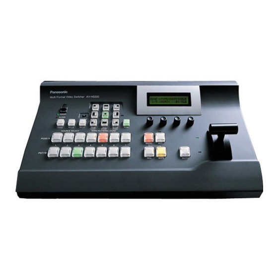
Operating Instructions Multi-Format Compact Live Switcher AV-HS300 Model No. Before operating this product, please read the instructions carefully and save this manual for future use. -
Page 2: Safety Precautions
Safety precautions CAUTION RISK OF ELECTRIC SHOCK DO NOT OPEN CAUTION: TO REDUCE THE RISK OF ELECTRIC SHOCK, DO NOT REMOVE COVER (OR BACK). NO USER SERVICEABLE PARTS INSIDE. REFER TO SERVICING TO QUALIFIED SERVICE PERSONNEL. The lightning flash with arrowhead symbol, within an equilateral triangle, is intended to alert the user to the presence of uninsulated “dangerous voltage”... -
Page 3: Important Safety Instructions
Safety precautions IMPORTANT SAFETY INSTRUCTIONS Read these operating instructions carefully before using the unit. Follow the safety instructions on the unit and the applicable safety instructions listed below. Keep these operating instructions handy for future reference. 1) Read these instructions. 2) Keep these instructions. -
Page 4: Table Of Contents
Contents Description ... 5 Features ... 5 1. Parts and their functions ... 6 Control panel ... 6 Crosspoint area ... 7 Wipe area ... 8 Transition area ... 9 LCD menu area ... 10 Rear panel connections area ... 11 2. -
Page 5: Description
Description This unit is a single-ME digital video switcher which supports multiple HD and SD formats. While featuring compact dimensions, it can optionally support HD analog component inputs (5) in addition to the five SDI inputs and one DVI-I input. Since a frame synchronizer is incorporated for each of the inputs, signals can be switched without “shocking”... -
Page 6: Parts And Their Functions
1. Parts and their functions 1-1. Control panel Power indicator [POWER] This lights when the power switch () is set to ON while power is supplied to the DC power socket. It goes off when the power switch () is set to OFF. ... -
Page 7: Crosspoint Area
1. Parts and their functions 1-2. Crosspoint area PGM/A bus crosspoint switches [PGM/A 1 to 7] These are used to select the PGM/A bus video signals. In the case of the flip-flop system, the main line video (PGM) signals are always selected. ... -
Page 8: Wipe Area
1. Parts and their functions 1-3. Wipe area Wipe pattern selector switches [WIPE PATTERN / FUNC] These are used to select the wipe patterns. Each switch is used to select one of the nine wipe patterns. The indicator of the switch for the selected pattern lights (in amber). When the [FUNC] switch () has been pressed and its indicator is lighted, the function setting menu is selected, and the indicator lights up green. -
Page 9: Transition Area
1. Parts and their functions 1-4. Transition area [BKGD] switch This executes the background transition when the [AUTO] switch () or fader lever () has been operated. When the [BKGD] switch is pressed and it is selected, its indicator is lighted in red. If the [KEY] switch () is now pressed, the indicator goes off, and the de-selected status is established. -
Page 10: Lcd Menu Area
1. Parts and their functions Fader lever This is used to execute background or key transitions. When it is moved as far as it will go, the transition is completed. When it has been operated during auto transition, auto transition will be switched to manual operation as soon as the fader position overtakes the amount of the transition being executed. -
Page 11: Rear Panel Connections Area
1. Parts and their functions 1-6. Rear panel connections area SDI signal input connectors [DIGITAL INPUTS 1 to 5] IN: SDI signal input; OUT: active through output DVI-I signal input connector [DIGITAL INPUTS 6 DVI-I] Analog HD component input connectors [ANALOG INPUTS 1 to 5] (optional) ... -
Page 12: Basic Operations
2. Basic operations 2-1. Transitions 2-1-1. Selecting the bus Press the crosspoint switches to select the material which will be targeted for the background transition. By pressing these switches, the signals are selected, and the indicators of the selected switches light. The color in which the switch indicators light differs depending on the operation status. -
Page 13: Selecting The Transition Mode
2. Basic operations 2-1-3. Selecting the transition mode Use the [BKGD] and [KEY] switches in the transition area to select the bus signals for which the transition is to be executed. If the switches have been pressed at the same time, both switches are selected. The indicator of a selected switch lights. -
Page 14: Wipe
2. Basic operations 2-2. Wipe 2-2-1. Selecting the wipe pattern Press one of the wipe pattern selector switches to select the desired wipe pattern from among the nine patterns available. The indicator of the selected wipe pattern selector switch lights in amber. 2-2-2. - Page 15 2. Basic operations Changing the soft effect amount On the BODR menu, turn [F3], and set the soft effect amount using the SOFT item. A setting of “0” means that the soft effect is OFF. Setting the border color On the BODR menu, turn [F4], and set the border color using the COLR item. When USR1 to 4 (user colors) has been selected, the color can be adjusted on the USR1 to 4 menu.
-
Page 16: Key
2. Basic operations 2-3. Key 2-3-1. Selecting the key source Selecting the key source signals The signals assigned to crosspoints 1 to 7 can be used for the key source signals. While holding down the [KEY-S] switch in the source selection area, press one of the B bus crosspoint switches [1] to [7] to select the key source signal. -
Page 17: Setting The Key
2. Basic operations 2-3-2. Setting the key Selecting the key type Press the [FUNC] switch to light its indicator, and then press the [KEY] switch to display the KEY menu. Turn [F1] to display the KEY menu (sub menu). ... -
Page 18: Selecting Key Fill
2. Basic operations 2-3-4. Selecting key fill Selecting the key fill signals In addition to the signals assigned to crosspoints 1 to 7, special fill colors can be used for the key fill signals. While holding down the [KEY-F] switch in the source selection area, press one of the B bus crosspoint switches 1 to 7 to select the key fill signal. -
Page 19: Key Decorations
2. Basic operations Adjusting the fill color The fill color can be adjusted when USR1 to 4 have been selected. Use of USR1 to 4 is shared by the border color, background color and edge color. Press the [FUNC] switch to light its indicator, and then press the [KEY] switch to display the KEY menu. ... - Page 20 2. Basic operations Adjusting the edge color The edge color can be adjusted when USR1, 2, 3 or 4 has been selected. Use of USR1 to 4 is shared by the border color, background color and fill color. Press the [FUNC] switch to light its indicator, and then press the [EDGE] switch to display the EDGE menu. ...
-
Page 21: Color Background
2. Basic operations 2-4. Color background The color background to be used by the bus can be set. One color among the eight preset colors (WHITE, YELLOW, CYAN, GREEN, MAGENTA, RED, BLUE and BLACK) and four user colors can be selected. HUE, SAT and LUM adjustments can be performed for the user colors. ... -
Page 22: Freezing The Input Signals
2. Basic operations 2-5. Freezing the input signals The input signals can be frozen and used. If any of the input signals has been frozen, the freeze status display LED lights. While signals are frozen, the tally signals of the corresponding input will not be output. ... -
Page 23: Frame Memory
2. Basic operations 2-6. Frame memory AUX output signals can be stored in the frame memory for use. Stored images can be used as the bus images by assigning the FMEM signals using the crosspoint assignment process. Images stored in the frame memory are also saved in the unit’s flash memory so they can be used even after the power is turned off. -
Page 24: Preset Memory
2. Basic operations 2-7. Preset memory Up to 10 panel settings can be stored in this memory (flash memory). The table below lists the settings which are stored. <Table of stored preset memory> Item Crosspoint A bus B bus KEY-S KEY-F AUX bus Color background... - Page 25 2. Basic operations RECALL: This is used to recall the preset memory data and change the panel settings. Press the [FUNC] switch to light its indicator, and then press the [MEM] switch to display the PSMEM (1/3) menu. Turn [F2], select “RECL” using the MODE item, turn [F3], and set the preset memory number using the NO. item.
-
Page 26: Setup
3. Setup 3-1. Setting the input signals 3-1-1. Setting the input signals (IN 1 to 5) If HD has been selected as the system format, SDI or analog HD component can be selected for each input. This selection is possible only when the analog HD input option has been connected. ... -
Page 27: Setting The Dvi Input Signals
3. Setup 3-1-3. Setting the DVI input signals Selecting the size XGA or SXGA can be input as the size. The frequency is fixed at 60 Hz. Press the [FUNC] switch to light its indicator, and then press the [SETUP] switch to display the SETUP menu. - Page 28 3. Setup Selecting the signal system Select the digital or analog system for the DVI input video signals. DIG (digital): Digital input signals of the DVI connector take effect. ANLG (analog): Analog input signals of the DVI connector take effect. On the DVIIN menu, turn [F4], and select the signal system using the MODE item.
-
Page 29: Setting The Output Signals
3. Setup 3-2. Setting the output signals 3-2-1. Types of output signals There are three output signal systems: PGM, PVW and AUX. PGM: This is the main-line output of the switcher; images with wipe, mix, key and other effects added to them are output. -
Page 30: Selecting The Video Format
3. Setup 3-3. Selecting the video format One system (input/output signal) video format can be selected. More than one format cannot be selected. If HD is selected, SDI or HD analog component can be selected for each input. (See 3-1-1) ... -
Page 31: Setting The Crosspoints
3. Setup 3-4. Setting the crosspoints 3-4-1. Assigning signals to the crosspoints External video input signals and internally generated signals can be assigned to crosspoint switches 1 to 7. Displaying the assignment statuses Press the [FUNC] switch to light its indicator, and then press the [XPT] switch to display the XPT menu. ... -
Page 32: Setting The Crosspoint Switching
3. Setup The table below lists the default settings. Switch Signal BLACK Internally generated signal, black INPUT1 External video input 1: SDI or analog HD component INPUT2 External video input 2: SDI or analog HD component INPUT3 External video input 3: SDI or analog HD component INPUT4 External video input 4: SDI or analog HD component INPUT5... -
Page 33: Setting The Sync Signals
3. Setup 3-5. Setting the sync signals The sync signals to be used by the system can be selected. External sync: For synchronization with an external sync signal (gen-lock). The reference input signal is looped through and output. BBST: Black burst signal (vertical phase of 0H) BBAD: Black burst signal (Vertical phase of 90H when the 59.94i or 59.94p format is selected;... -
Page 34: Adjusting The Output Signal Phase
3. Setup 3-6. Adjusting the output signal phase The phase of the output video signals can be adjusted. Press the [FUNC] switch to light its indicator, and then press the [SETUP] switch to display the SETUP menu. Turn [F1] to display the OUPHS menu. ... - Page 35 3. Setup <Phase adjustment setup> ��� ������� ��������� � �� ������ ����� ������� ����� �� ����� �������� ������ ������� � �� ������ ��� ����� ��� ��� ��� �������� ������� �� ����� ��� ���� ���� ������������� � ����� � ����� ������ �� ������ � � ����� �������� ���� ������ AVDL Range: Range for automatic phase adjustment.
-
Page 36: Network Settings
3. Setup 3-7. Network settings Set up the network for transmitting image files by Ethernet. For details on image transmission method, refer to “5. Image transmission functions”. The network setup is: IP address: 192.168.0.10, subnet mask: 255.255.255.0 and gateway: 0.0.0.0 (unused). When using the host computer with settings matching the network setup, it is not necessary to setup via the menu. - Page 37 3. Setup Setting the gateway On the SETUP menu, turn [F1] to display the GW (Gateway) menu. Turn [F2] to select the setting location. An asterisk ( ) appears at the setting location. Turn [F3] to set the number, and press the [F3] switch to enter the setting. If the setting is not entered even though it has been changed, “...
-
Page 38: Other Settings
3. Setup 3-8. Other settings 3-8-1. LCD backlight The LCD backlight can be set to ON or OFF. Press the [FUNC] switch to light its indicator, and then press the [SETUP] switch to display the SETUP menu. Turn [F1] to display the SYS menu. Turn [F2], and select ON or OFF for the backlight using the BL item. -
Page 39: Status Displays
3. Setup 3-9. Status displays The statuses can be displayed. Press the [FUNC] switch to light its indicator, and then press the [SETUP] switch to display the SETUP menu. Turn [F1] to display the STATS menu. ALM (alarm): Indicates a fan and/or power supply alarm. -
Page 40: Setting Menu Table
4. Setting menu table A setting is entered when an item is selected and then the [F1], [F2], [F3] or [F4] switch is pressed. (It will not be entered unless the switch is pressed.) Submenu Menu Turn F1 to select. TIME BKGD WIPE... - Page 41 4. Setting menu table Submenu Menu Turn F1 to select. CBGD USR4(*) KADJ FILL KEY-F Link from switch USR1(*) USR2(*) USR3(*) USR4(*) EDGE EDGE USR1(*) USR2(*) Parameter 1 Turn F2 to select. Parameter Setting range 0 to 359 Default value TYPE Parameter Setting range SELF...
- Page 42 4. Setting menu table Submenu Menu Turn F1 to select. EDGE USR3(*) USR4(*) PSMEM PSMEM FMEM XPTAS XPTAS XPTSW Parameter 1 Turn F2 to select. Parameter Setting range 0 to 359 Default value Parameter Setting range 0 to 359 Default value Parameter MODE Setting range STOR...
- Page 43 4. Setting menu table Submenu Menu Turn F1 to select. SETUP IN1–5 1/14 DVIIN 2/14 3/14 FORMT 4/14 5/14 OUPHS 6/14 7/14 MASK 8/14 9/14 10/14 11/14 Parameter 1 Turn F2 to select. Parameter Setting range IN1 to 5 Default value IN1 to 5 SIZE Parameter...
- Page 44 4. Setting menu table Submenu Menu Turn F1 to select. SETUP 12/14 INIT 13/14 STATS 14/14 Parameter 1 Turn F2 to select. Parameter Setting range ON Default value INIT Parameter Setting range EXEC () Parameter Display only POWR F, P Parameter 2 Parameter 3 Turn F3 to select.
-
Page 45: Image Transmission Functions
5. Image transmission functions This unit comes with a function for transmitting still images from the host computer to the unit via Ethernet and a function for importing still images from the unit into the host computer. The image transmission program must be installed in the host computer from the CD-ROM supplied in order to use these functions. - Page 46 5. Image transmission functions How to install the program This section describes how to install the image transmission program (HS300 Tool). Windows XP is used as the host computer’s operating system in the example given here. 1. Insert the CD-ROM supplied with the unit into the CD-ROM drive of the host computer in which the program will be installed.
- Page 47 5. Image transmission functions Operation This section describes how to operate the image transmission program (HS300 Tool). <Startup> On the Start menu of Windows, select [Programs] [Panasonic] [HS300Tool]. The main screen now appears. <Exit> Click the [CLOSE] button.
- Page 48 5. Image transmission functions <Transmitting images to the unit> 1. Select the mode. Check that “To HS300” appears in the [Mode] field. If “From HS300” appears instead, click the Mode button so that “To HS300” appears. 2. When the [Select Image] button is clicked, the file selection dialog box appears on the screen. Select the image file to be transmitted, and click [OK].
-
Page 49: External Interfaces
6. External interfaces This unit comes with RS-422, GPI and tally connectors to serve as external interfaces. 6-1. RS-422 connector This enables the unit to be controlled by an external device. Use it with the settings below. Baud rate: 38400 bps Parity: Stop bit: 1 bit... -
Page 50: Connections
HD camera Component Analog HD/SDI converter DVI or VGA SDI (HD) SDI (HD) SDI (HD) SDI (HD) HD Component HD component monitor SDI (HD) HD SDI monitor SDI (HD) HD SDI monitor Multi-format compact live switcher AV-HS300 AC adapter AW-PS505A... - Page 51 SDI (HD) SDI (HD) HD Component HD Component HD Component DVI or VGA Optional HD analog inputs HD Component HD component monitor SDI (HD) HD SDI monitor HD component monitor HD Component Multi-format compact live switcher AV-HS300 AC adapter AW-PS505A...
-
Page 52: Appearance
8. Appearance Unit: mm ���... -
Page 53: Specifications And Standard Accessories
Specifications and standard accessories Specifications Inputs Video inputs6 (SDI5, DVI-I1, analog HD5 (optional)) Reference1 Outputs Video outputs3 (PGM, PVW, AUX) PGM: SDI2 outputs, analog HD1 output PVW: SDI1 output, analog HD1 output AUX: SDI2 outputs, analog HD1 output Reference1 Signal formats SD: 480/59.94i, 576/50i HD: 1080/59.94i, 1080/50i, 720/59.94p, 720/50p Signal processing... -
Page 54: Optional Accessories
Specifications and standard accessories SDI outputs SD (SMPTE 259M standard complied with) • Output return loss • Output level • Rise time • Fall time • Difference between rise time and fall time • Jitter Analog HD input HD analog component Y/Pb/Pr (1.0 Vp-p, 75 ) (*option) IN1 to 5 Analog HD output... -
Page 55: Appendix (Glossary)
Appendix (glossary) Defined below are the terms used in this manual. Word AB Bus AB Bus system Ancillary Data Aspect ratio [Auxiliary Bus] AVDL [Automatic Video Delayline] Automatic phase adjustment Black burst Border Clip Color Background Density DVI [Digital Visual Interface] Ethernet Flip Flop system Frame Memory... - Page 56 Appendix (glossary) Word Genlock [General Purpose Interface] Key Edge Key Fill Key Inversion Key Source Linear Key [Luminance] Luminance Key [Mix Effect] Preview Program Bus Preset Bus Preset Memory RS-422 [Saturation] A function for synchronizing the video signals using an external sync signal as the reference.
- Page 57 Appendix (glossary) Word [Serial Digital Interface] Self Key Tally Transition Tri Sync Wipe The standard by which video signals in various SD and HD formats are transmitted along a single coaxial cable. A function that creates key signals from key fill signals for combining keys. The signal which outputs the program output statuses of the input signals to an external device.
- Page 60 PANASONIC BROADCAST & TELEVISION SYSTEMS COMPANY UNIT COMPANY OF PANASONIC CORPORATION OF NORTH AMERICA Executive Office: One Panasonic Way 4E-7, Secaucus, NJ 07094 (201) 348-7000 EASTERN ZONE: One Panasonic Way 4E-7, Secaucus, NJ 07094 (201) 348-7621 Southeast Region: 1225 Northbrook Parkway, Ste 1-160, Suwanee, GA 30024 (770) 338-6835...