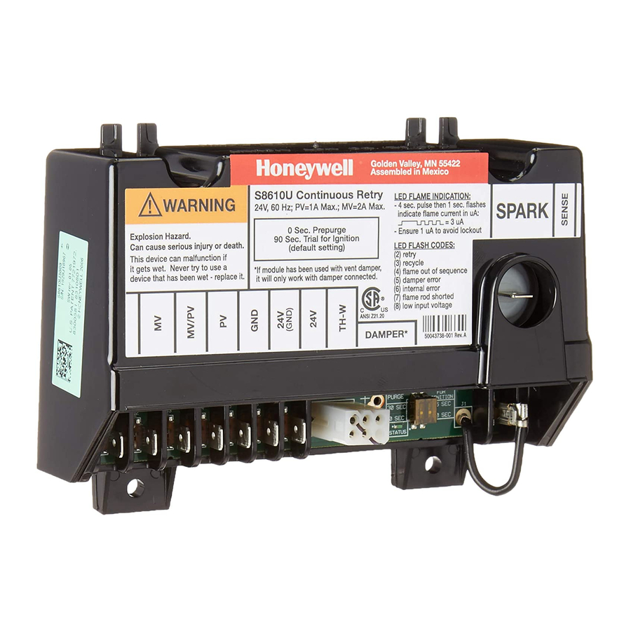
Honeywell S8610U Installation Instructions Manual
Pilot gas ignition module
Hide thumbs
Also See for S8610U:
- User manual ,
- Installation instructions manual (25 pages) ,
- Quick reference manual (2 pages)
Table of Contents
Advertisement
SUPER TRADELINE
APPLICATION
The SUPER TRAD ELINE® S8610U Universal Replace
ment Ignition Module is designed to provide easy field
replacement of a wide range of intermittent pilot ignition
modules manufactured by Honeywell, Robertshaw,
Penn-Johnson and others. The S8610U module provides
ignition sequence, flame monitoring, and safety shutoff
for intermittent pilot central furnaces, residential boilers,
and other heating appliances. The S8610U replaces
existing flame rectification type intermittent pilot ignition
modules with the following characteristics:
•
Single rod (local sense) or two rod (remote sense)
flame sensing.
•
Non-100 percent shutoff, 100 percent shutoff/lockout,
or 100 percent shutoff/continuous retry.
•
Natural or LP gas.
•
Shutoff/lockout times of 30 seconds or longer.
•
Prepurge times of four seconds or shorter.
•
Pilot burners with flow rates of 1500 Btuh or less.
•
With or without vent dampers.
A
WARNING
Check Table 1 before replacing an existing
intermittent pilot module with the S8610U. If the
existing module is not listed, do not use the
S8610U to replace it unless you are certain the
specifications of the S8610U match those of the
existing module.
A complete list of the specific Honeywell and other
modules that the SUPER TRADELINE® S8610U is
designed to replace is provided in Table 1.
The S8610U SUPER TRADELINE® package contains
complete, easy-to-use instructions, plus the accessories
required to adapt the existing spark cable (Rajah, stud,
nail, or other) to the spark terminal on the S8610U. It also
provides labels to help assure proper marking of the wires
attached to the existing module.
®U.S. Registered Trademark
Copyright © 1996 Honeywell Inc. • All Rights Reserved
Universal Intermittent Pilot Module
®
Installation INSTRUCTIONS
The S8610U SUPER TRADELINE® Universal Module is
not designed to replace controls with the following
characteristics:
•
Flame sensing other than by flame rectification (White
Rodgers Cycle-Pilot®, or Robertshaw thermal sensing).
•
Flame rectification modules with shutoff/lockout times
of less than 30 seconds, prepurge times of more than 4
seconds, or pilot burners larger than 1500 Btuh.
•
Standing pilot appliances.
Honeywell provides additional control packages to
accomplish these replacements. See the Honeywell
Electronic Ignition Service Manual, form 70-6604, or call
your Honeywell wholesaler.
SPECIFICATIONS
Electrical Ratings:
Voltage: 24V, 60 Hz.
Current Draw: 1A pilot valve, 2A main valve.
Valve Contact Rating: 0.2A.
Trial For Ignition:
90 seconds maximum, then 100 percent shutoff (pilot and
main gas).
Continuous Retry:
Five-minute minimum (six-minute nominal) delay if pilot
fails to light during trial for ignition. After delay, trial for
ignition is repeated. This sequence (trial, delay, trial, delay)
continues until pilot lights or call for heat ends.
Flame Failure Response Time:
0.8 sec max at 1.0 uA flame current.
Ambient Operating Temperature:
-40°F to 165°F (-40°C to 74°C). (If main valve current is 1A
or less, 175°F (79°C) maximum ambient applies.)
Honeywell
S8610U
6 9 - 0 7 2 9 - 3
Advertisement
Table of Contents

Related Manuals for Honeywell S8610U


Summary of Contents for Honeywell S8610U
- Page 1 (Rajah, stud, -40°F to 165°F (-40°C to 74°C). (If main valve current is 1A nail, or other) to the spark terminal on the S8610U. It also or less, 175°F (79°C) maximum ambient applies.) provides labels to help assure proper marking of the wires attached to the existing module.
- Page 2 S8610U UNIVERSAL INTERM ITTENT P H O T MODULE Table 1. S8610U Replaces these Ignition Modules. Camstat S86H1089 CSA42A-603R G60PAG-5 G60RCG-2 G67AG-8 IPI-24-00 S86H1097 CSA42A-604R G60PAG-6 G60RCJ-1 G67BG-2 S86H1105 CSA43A-600R G60PAJ-1 G60RDG-1 G67BG-3 Fenwal S86H1121 CSA44A-600R G60PAK-1 G60RDK-1 G67BG-4 05-203025-005...
- Page 3 S8610U UNIVERSAL INTERM ITTENT PILO T MODULE Dust or Grease Accumulation PLANNING THE INSTALLATION Heavy accumulations of dust or grease can cause controls to malfunction. Where dust or grease can be a problem, provide covers for the module and the gas WARNING control to limit contamination.
- Page 4 Refer to Fig. 1 for mounting recommendations. When it is necessary to drill new mounting holes, use the S8610U as a template to mark mounting hole pattern. Drill new holes, as required. Fasten securely with four No. 6-32 machine or No. 8 sheetmetal screws.
- Page 5 Arc 1/8 in. (3 mm) Voltage output is okay. insulated boot or longer. Table 3. Conversion from Honeywell S86, S90, S8600 and S8610 to S8610U1003. Replacement Control Old Control S8600A,B,C Terminal S8610A,B,C S8600F,H,M...
- Page 6 S8610U UNIVERSAL INTERM ITTENT P H O T MODULE Table 4. Conversion from Robertshaw SP715 and SP735C to S8610U1003 (Includes 780-XXX and USI715U). Replacement Old Control SP715 and SP735 Control (includes 780-XXX and USI 715U)c> d Honeywell Terminal Function S8610U1003...
- Page 7 S8610U UNIVERSAL INTERM ITTENT P H O T MODULE T a b le 5 . C o n v e r s i o n f r o m P e n n - J o h n s o n C S A — ( A ll) , G 6 0 , G 6 5 , G 6 6 , G 6 7 , G 6 0 0 , G 6 7 0 O r G 7 7 0 t o S 8 6 1 0 U 1 0 0 3 .
- Page 8 S8610U UNIVERSAL INTERM ITTENT P H O T MODULE Table 6. Conversion from Camstat, Fenwal or HSC to S8610U1003. Replacement Control Old Control Terminal Honeywell CAMSTAT FENWAL HSC 1003-3 IPI-24-00 05-20X Function S8610U1003 and 1003-300 Procedural Notes M a in v a lv e M A IN V A L V E —...
- Page 9 REMOVE JUMPER AND CONNECT SENSE TERMINAL ON TWO ROD APPLICATION ONLY. IF THE VENT DAMPER IS CONNECTED, WIRE 24V TERMINAL, AS SHOWN. CONNECT VENT DAMPER CABLE IN PLACE OF PLUG SHIPPED WITH THE S8610U. IF NO VENT DAMPER IS CONNECTED, DO NOT WIRE 24V TERMINAL.
- Page 10 S8610U UNIVERSAL INTERM ITTENT PILO T MODULE START STAGE 1 TRIAL FOR IGNITION STAGE 2 MAIN BURNER OPERATION Fig. 4. S8610U in typical ST9120 application. STARTUP AND CHECKOUT Test for gas leak before gas control if piping has been Check out the gas control system: disturbed.
- Page 11 S8610U UNIVERSAL INTERM ITTENT P L O T MODULE MAINTENANCE Step 3: Review normal operating sequence and module specifications. See Operation and Application sections. WARNING FIRE OR EXPLOSION HAZARD Step 4: Reset the module. CAN CAUSE PROPERTY DAMAGE, Turn the thermostat to its lowest setting.
- Page 12 S8610U UNIVERSAL INTERM ITTENT PILO T MODULE S T A R T TURN OFF GAS SUPPLY. NOTE: Before troubleshooting, familiarize yourself with the startup and checkout procedure. TURN THERMOSTAT (CONTROLLER) TO CALL FOR HEAT. POWER TO MODULE. (24V NOMINAL) CHECK AT TH-W TERMINAL, Check line voltage power, low voltage transformer, limit controller, thermostat (controller) and wiring.
- Page 13 S8610U UNIVERSAL INTERM ITTENT P H O T MODULE Step 2: Check ignition system grounding. Nui OPERATION sance shutdowns are often caused by a poor or Module operation can be conveniently divided into two erratic ground. phases for the S8610: A common ground, usually supplied by the pilot •...
- Page 14 S8610U UNIVERSAL INTERM ITTENT PILO T MODULE APPEARANCE CAUSE Step 4: Check pilot and main burner lightoff. Set the thermostat to call for heat. SMALL BLUE FL CHECK FOR LACK OF GAS FROM: Watch the pilot burner during the ignition sequence to •...
- Page 15 S8610U UNIVERSAL INTERM ITTENT PILO T MODULE S T A R T TURN OFF GAS SUPPLY. NOTE: Before troubleshooting, familiarize yourself with the startup and checkout procedure. TURN THERMOSTAT (CONTROLLER) TO CALL FOR HEAT. POWER TO MODULE. (24V NOMINAL) CHECK AT TH-W TERMINAL, Check line voltage power, low voltage transformer, limit controller, thermostat (controller) and wiring.
- Page 16 S8610U UNIVERSAL INTERM ITTENT P H O T MODULE INTERNAL WIRING ALTERNATE LIMIT CONTROLLER LOCATION. EXTERNAL WIRING 3 AMP NONREPLACEABLE FUSE. FUSE BLOWS WHEN VENT DAMPER IS PLUGGED IN AND POWER IS APPLIED. SEPARATE SENSOR IS USED ON TWO-ROD SYSTEMS ONLY. DISCONNECT BLACK JUMPER WIRE FROM SENSE TERMINAL, CUT AT CIRCUIT BOARD AND DISCARD.
- Page 17 S8610U UNIVERSAL INTERM ITTENT PILO T MODULE ANSI STANDARDS Exhibit A Recommended Procedure for Safety Inspection of an Existing Appliance Installation as A Preliminary Step to Applying an Automatic Intermittent Pilot System The following procedure is intended as a guide to aid in determining that an appliance is properly installed and is in a safe condition for continuing use.
- Page 18 S8610U UNIVERSAL INTERM ITTENT PILO T MODULE Exhibit B Procedure for Installing Automatic Intermittent Pilot Systems Prior to beginning this procedure, a preliminary examination of the appliance and the automatic intermittent pilot system should be made to determine that the automatic intermittent pilot system can be properly applied to the appliance.
- Page 19 69-0729—3...
- Page 20 Honeywell Home and Building Control Home and Building Control Honeywell International, Inc. Honeywell Limited-Honeywell Limitée 1985 Douglas Drive North 35 Dynamic Drive S T \ Printed in U SA. on recycled paper containing at least 10% Golden Valley, MN 55422 Scarborough, Ontario post-consumer paper fibers.