
Related Manuals for Acer ASPIRE 5252


Summary of Contents for Acer ASPIRE 5252
- Page 1 Aspire 5252/5552/5552G Series Service Guide Service guide files and updates are available on the ACER/CSD web; for more information, please refer to http://csd.acer.com.tw PRINTED IN TAIWAN...
-
Page 2: Revision History
Revision History Please refer to the table below for the updates made on Aspire AS5552/AS5552G service guides. Date Chapter Updates... - Page 3 Copyright Copyright © 2010 by Acer Incorporated. All rights reserved. No part of this publication may be reproduced, transmitted, transcribed, stored in a retrieval system, or translated into any language or computer language, in any form or by any means, electronic, mechanical, magnetic, optical, chemical, manual or otherwise, without the prior written permission of Acer Incorporated.
-
Page 5: Conventions
Conventions The following conventions are used in this manual: SCREEN MESSAGES NOTE WARNING CAUTION IMPORTANT NOTE: This symbol where placed in the Service Guide designates a component that should be recycled according to the local regulations. Denotes actual messages that appear on screen. - Page 6 DIFFERENT part number code to those given in the FRU list of this printed Service Guide. You MUST use the list provided by your regional Acer office to order FRU parts for repair and service of customer machines.
-
Page 7: Table Of Contents
Your Acer Notebook tour ........ - Page 8 Table of Contents Removing the Touchpad FFC ........70 Removing the Card Reader Board (Discrete Only) .
- Page 9 Troubleshooting Common Problems ..........149 Power On Issue .
- Page 10 Table of Contents...
-
Page 11: System Specifications
• Up to 4 GB of DDR3 system memory, upgradable to 8 GB using two soDIMM modules Display • 15.6" HD 1366 x 768 pixel resolution, high-brightness (200-nit) Acer CineCrystal™ TFT LCD • 16:9 aspect ratio Chapter 1 Chapter 1... - Page 12 WMV9 (VC-1) and H.264 (AVC) decoding • Microsoft® DirectX® Video Acceleration (DXVA) application interface (API) • HDMI™ (High-Definition Multimedia Interface) with HDCP (High-bandwidth Digital Content Protection) support Audio • Built-in Acer mono speaker • High-definition audio support • Built-in microphone • MS-Sound compatible Storage •...
-
Page 13: Optical Media Drive
Write: 24X CD-R, 16X CD-RW, 8X DVD-R, 8X DVD+R, 4X DVD-R DL, 4X DVD+R DL, 6X DVD-RW, 8X DVD+RW, 5X DVD-RAM Communication • Acer Video Conference, featuring: • Acer Crystal Eye webcam with 1280 x 1024 resolution • WLAN: • Acer InviLink™ Nplify™ 802.11b/g/n Wi-Fi CERTIFIED™ •... -
Page 14: Special Keys And Controls
Special Keys and Controls • Keyboard • 103-/104-/107-key Acer FineTip keyboard with independent standard numeric keypad, international language support • Touchpad • Multi-gesture touchpad, supporting two-finger scroll, pinch, rotate, flip • Media keys • Media control keys (printed on keyboard): play/pause, stop, previous, next, volume up,... -
Page 15: Optional Items
• Utilities and tools • Acer Accessory Store (Belgium, France, Germany, Italy, Netherlands, Spain, Sweden, UK only) • Acer Identity Card • Acer Registration • Acer Updater • eBay® shortcut 2009 (Canada, France, Germany, Italy, Mexico, Spain, UK, US only) •... -
Page 16: System Block Diagram
System Block Diagram Discrete Model VRAM 1GB 64M16 x 8 DDR3 ATI M97 Madisan/Park uFCBGA-962 LVDS HDMI Conn. LAN(GbE) MINI Card 1 Broadcom WLAN BCM57780 GPP1 GPP0 RJ45 Fan Control RTC CKT. Extend Card/B 1. USB X2 LID SW / MEDIA/B 2. -
Page 17: Uma Model
UMA Model LVDS HDMI Conn. LAN(GbE) MINI Card 1 Broadcom WLAN BCM57780 RJ45 RTC CKT. LID SW / MEDIA/B Fan Control Power On/Off CKT. Extend Card/B DC/DC Interface CKT. 1. USB X2 2. ODD X1 Power Circuit Chapter 1 Danube AMD S1G4 Processor Memory BUS(DDR3) uPGA-638 Package... -
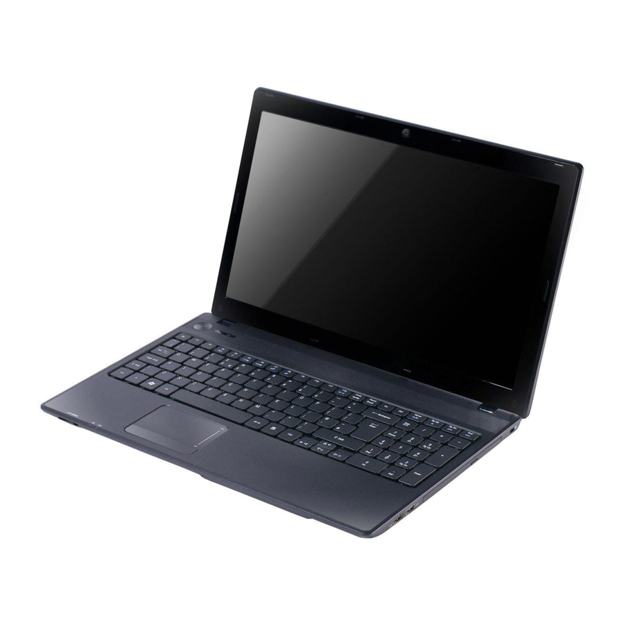
Page 18: Your Acer Notebook Tour
Your Acer Notebook tour Front View Icon Item Acer Crystal Eye Web camera for video communication webcam (for selected models). Display screen Also called Liquid-Crystal Display (LCD), displays computer output. Indicates when the hard disk drive is active. Communication Indicates the computer’s wireless connectivity indicator device status. -
Page 19: Rear View
Icon NOTE: The 2-in1 card reader will be on the front left for UMA models and on the front right for discrete models. Rear View Icon Left View Icon Chapter 1 Item Indicates the computer’s power status. Power Indicates the computer’s battery status. Battery 1. -
Page 20: Right View
Icon Right View Icon USB 2.0 ports Optical drive Optical disk access indicator Optical drive eject button Emergency eject hole Kensington lock slot Item HDMI Connect to HDMI devices USB 2.0 ports Connect to USB 2.0 devices (e.g. USB mouse, USB camera). -
Page 21: Base View
Base View Icon Indicators The computer has several easy-to-read status indicators. Icon Power Battery Communication indicator Chapter 1 Item Battery bay Houses the computer's battery pack. Battery release Releases the battery for removal. latch Hard disk bay Houses the computer's hard disk (secured with screws). -
Page 22: Touchpad Basics
Touchpad Basics The following items show you how to use the Touchpad: • Move your finger across the Touchpad (1) to move the cursor. • Press the left (2) and right (3) buttons located beneath the Touchpad to perform selection and execution functions. -
Page 23: Using The Keyboard
Using the Keyboard The keyboard has full-sized keys and an embedded numeric keypad, separate cursor, lock, Windows, function and special keys. Lock Keys and embedded numeric keypad The keyboard has two lock keys which you can toggle on and off. Lock key Caps Lock When Caps Lock is on, all alphabetic characters typed are in uppercase. -
Page 24: Windows Keys
Windows Keys The keyboard has two keys that perform Windows-specific functions. Windows key Pressed alone, this key has the same effect as clicking on the Windows Start button; it launches the Start menu. It can also be used with other keys to provide a variety of functions: <... -
Page 25: Hot Keys
Hot Keys The computer employs hotkeys or key combinations to access most of the computer’s controls like screen brightness, volume output and the BIOS utility. To activate hot keys, press and hold the <Fn> key before pressing the other key in the hotkey combination. Hotkey Icon <Fn>... -
Page 26: Hardware Specifications And Configurations
45nm 512KB*2 3600 45nm 1024KB*2 3600 45nm 512KB*3 3600 45nm 512KB*3 3600 45nm 512KB*4 3600 45nm 512KB*4 Core Package Acer PN Voltage uPGA- 0.8125- KC.V0002.140 1.3125 uPGA- 0.8000- KC.AP002.340 1.2000 uPGA- 0.8000- KC.AP002.350 1.3125 uPGA- 0.7750- KC.TP002.540 1.1875 uPGA- 0.7875- KC.PP002.840... - Page 27 Northbridge Item Chipset AMD RS880M Package uFCBGA-528p Features • CPU HyperTransport™ Interface • Caspian-series processors. • ATI HyperMemory • PCI ExpressR Interface • A-Link Express II Interface • Northbridge-Southbridge messaging functionalities • 2D Acceleration • 3D Acceleration • Motion Video Acceleration •...
- Page 28 • Suspend to RAM (S3)/Disk (S4) • Various hot-keys for system control • Support SMBIOS 2.3, PCI2.2. • Refer to Acer BIOS specification. • DMI utility for BIOS serial number configurable/asset tag • Support PXE • Support Y2K solution •...
- Page 29 System Memory Item Memory controller Memory size DIMM socket number Supports memory size per socket Supports maximum memory size Supports DIMM type Supports DIMM Speed Support DIMM voltage Supports DIMM package Memory Combinations Slot 1 1024MB 1024MB 1024MB 2048MB 2048MB 2048MB 2048MB 4096MB...
- Page 30 Wireless Module 802.11b/g/n Item Chipset Atheros HB93/HB95/ HB97, Broadcom 943225/43225/ 4313/ 4312, RTL8192 Data throughput 11~54 Mbps, up to 270 Mbps for Draft-N Protocol 802.11 b+g, Draft-N Interface PCI bus (mini PCI socket for wireless module) Bluetooth Interface Item Chipset Atheros AR3011/ Broadcom BCM2070/ Broadcom BCM2046 Data throughput TX 1.2Mbits/sec...
- Page 31 Super-Multi Drive Interface Item Vendor & model name HLDS Super-Multi Drive DL 8X GT30N LF, SONY Super-Multi Drive DL 8X AD-7590S LF, SONY Super-Multi Drive DL 8X AD-7580S LF, TOSHIBA Super-Multi Drive DL 8X TS-L633B LF, TOSHIBA Super-Multi Drive DL 8X TS-L633C Performance With CD Diskette...
- Page 32 Audio Subsystem Item Audio Codec Chipset Realtek ALC272 Package 48pin LQFP Speaker Amplifier TPA6017A2_TSSOP20 Audio Port Internal 1 mic, 1 speaker Compatibility Dolby® Digital Live, DTS® CONNECT™, Dolby® Home Theater, and SRS® programs Sampling Rate 44.1k/48k/96k/192kHz External Mic jack Headphone jack Graphics Controller Item VGA Chip...
- Page 33 USB Port Item USB compliance level USB 1.1 / USB 2.0 compatibility OHCI/EHCI EHCI/OHCI 9 Number of USB port(s) Location 2 (right side), 1 (left side) HDMI Port Item Compliance level Data throughput Number of HDMI port(s) Location PCMCIA Port (Not available in this model) Item PCMCIA controller Supports card type...
- Page 34 Keyboard Item Type New Acer AC7T flat keyboard Total number of 103-US/104-UK keys keypads Windows logo key Internal & external keyboard work simultaneously Features • • • • • I/O Ports Item I/O support • 2-in-1 card reader (SD™, MMC) •...
- Page 35 LED 15.6" Item Vendor/model name Screen Diagonal (mm) Active Area (mm) Display resolution (pixels) Pixel Pitch (mm) Pixel Arrangement Display Mode Typical White Luminance (cd/m2) also called Brightness Contrast Ratio Response Time (Optical Rise Time/ Fall Time) msec Typical Power Consumption (watt) Weight (without inverter) Physical Size (mm) Electrical Interface...
- Page 36 LCD Inverter Item Vendor & model name Brightness conditions Input voltage (v) Input current (mA) Output voltage (V, RMS) Output current (mA, RMS) Output voltage frequency (KHz) Graphic Driver Supported Resolution Resolution 800x600p/60Hz 4:3 1024x768p/60Hz 4:3 1280x600/60Hz 16:9 1280x720/60Hz 16:9 1280x768/60Hz 16:10 1360x768/60Hz 16:9 Camera...
- Page 37 Card Reader Item Chipset Package Feature Supports Maximum size (please specify max supporting size for each card) System LED Indicator Item Lock Display on panel (Launch Manager) System state Blue color solid on: System on Blue color off: System off Amber color blinking: S3 state HDD access state Blue color led blinking...
- Page 38 Chapter 1...
-
Page 39: System Utilities
System Utilities BIOS Setup Utility The BIOS Setup Utility is a hardware configuration program built into your computer’s BIOS (Basic Input/ Output System). Your computer is already properly configured and optimized, and you do not need to run this utility. However, if you encounter configuration problems, you may need to run Setup. -
Page 40: Aspire As5552/As5552G Bios
Aspire AS5552/AS5552G BIOS Information The Information screen displays a summary of the computer hardware information. Information Main Security C P U T y p e C P U T y p e C P U S p e e d C P U S p e e d H D D M o d e l N a m e : H D D M o d e l N a m e :... -
Page 41: Main
Main The Main screen allows the user to set the system time and date as well as enable and disable boot options and recovery. Information Main S y s t e m Ti m e : S y s t e m Ti m e : S y s t e m D a t e : S y s t e m D a t e : To t a l M e m o r y :... -
Page 42: Security
Security The Security screen contains parameters that help safeguard and protect your computer from unauthorized use. NOTE: System BIOS does not support Trusted Platform Module (TPM). Information Main Security S u p e r v i s o r P a s s w o r d I s : S u p e r v i s o r P a s s w o r d I s : U s e r P a s s w o r d I s : U s e r P a s s w o r d I s :... -
Page 43: Setting A Password
Setting a Password Follow these steps as you set the user or the supervisor password: Use the ↑ and ↓ keys to highlight the Set Supervisor Password parameter and press the Enter key. The Set Supervisor Password box appears: Type a password in the “Enter New Password” field. The password length can not exceed 8 alphanumeric characters (A-Z, a-z, 0-9, not case sensitive). -
Page 44: Changing A Password
Changing a Password Use the ↑ and ↓ keys to highlight the Set Supervisor Password parameter and press the Enter key. The Set Supervisor Password box appears. Type the current password in the Enter Current Password field and press Enter. Type a password in the Enter New Password field. -
Page 45: Boot
Boot This menu allows the user to decide the order of boot devices to load the operating system. Bootable devices includes the USB diskette drives, the onboard hard disk drive and the DVD drive in the module bay. Select Boot menu to select specific devices to support boot. Information Main B o o t p r i o r i t y o r d e r :... -
Page 46: Exit
Exit The Exit screen allows you to save or discard any changes you made and quit the BIOS Utility. Information Main E x i t S a v i n g C h a n g e s E x i t S a v i n g C h a n g e s E x i t D i s c a r d i n g C h a n g e s E x i t D i s c a r d i n g C h a n g e s L o a d S e t u p D e f a u l t s... -
Page 47: Bios Flash Utilities
BIOS Flash Utilities The BIOS flash memory update is required for the following conditions: • New versions of system programs • New features or options • Restore a BIOS when it becomes corrupted. Use the flash utility to update the system BIOS flash ROM. NOTE: If you do not have a crisis recovery diskette at hand, then you should create a Crisis Recovery Diskette before you use the flash utility. -
Page 48: Dos Flash Utility
DOS Flash Utility Perform the following steps to use the DOS Flash Utility: Press F2 during boot to enter the Setup Menu. Select Boot Menu to modify the boot priority order, for example, if using USB HDD to Update BIOS, move USB HDD to position 1. - Page 49 In flash BIOS, the message Please do not remove AC Power Source displays. NOTE: If the AC power is not connected, the following message displays. Plug in the AC power to continue. Flash is complete when the message Flash programming complete displays. Chapter 2...
-
Page 50: Winflash Utility
WinFlash Utility Perform the following steps to use the WinFlash Utility: Double-click the WinFlash executable. Click OK to begin the update. A progress screen displays. Chapter 2... -
Page 51: Remove Hdd/Bios Password Utilities
Remove HDD/BIOS Password Utilities This section provides you with details about removing HDD/BIOS password: Remove HDD Password: If you key in the wrong HDD password three times, an error is generated. To reset the HDD password, perform the following steps: After the error is displayed, select the Enter Unlock Password option on the screen. - Page 52 Removing BIOS Passwords To clear the User or Supervisor passwords, open the DIMM door and use a metal instrument to short the R334 point. Cleaning BIOS Passwords To clean the User or Supervisor passwords, perform the following steps: From a DOS prompt, execute clnpwd.exe Press 1 or 2 to clean the desired password shown on the screen.
-
Page 53: Using Boot Sequence Selector
Using Boot Sequence Selector The Boot Sequence Selector allows the boot order to be changed without accessing the BIOS. To use Boot Sequence Selector, perform the following steps: Enter into DOS. Execute BS.exe to display the usage screen. Select the desired boot sequence by entering the corresponding sequence. For example, enter BS 2 to change the boot sequence to HDD | CD ROM | LAN | Floppy. -
Page 54: Using Dmitools
The following examples show the commands and the corresponding output information. Read DMI Information from Memory Input: dmitools /r Output: Manufacturer (Type1, Offset04h): Acer Product Name (Type1, Offset05h): JE51_DN Serial Number (Type1, Offset07h): 01234567890123456789 UUID String (Type1, Offset08h): xxxxxxxx-xxxx-xxxx-xxxx-xxxxxxxxxxxx Write Manufacturer Name to EEPROM... -
Page 55: Machine Disassembly And Replacement
Machine Disassembly and Replacement IMPORTANT: The outside housing and color may vary from the mass produced model. This chapter contains step-by-step procedures on how to disassemble the notebook computer for maintenance and troubleshooting. Disassembly Requirements To disassemble the computer, you need the following tools: •... -
Page 56: Pre-Disassembly Instructions
Pre-disassembly Instructions Before proceeding with the disassembly procedure, make sure that you do the following: 1. Turn off the power to the system and all peripherals. 2. Unplug the AC adapter and all power and signal cables from the system. NOTE: Make sure you match the AC adapter with the correct model. -
Page 57: Disassembly Process
Disassembly Process IMPORTANT: The LCD module cannot be disassembled outside of factory conditions. If any part of the LCD module is faulty, such as the camera, antenna or LCD panel, the whole module must be replaced. The disassembly process is divided into the following stages: •... -
Page 58: External Module Disassembly Process
External Module Disassembly Process IMPORTANT: The outside housing and color may vary from the mass produced model. External Modules Disassembly Flowchart The flowchart below gives you a graphic representation of the external module disassembly sequence and instructs you on the components that need to be removed during servicing. For example, if you want to remove the keyboard, you must first remove the switch board. -
Page 59: Removing The Battery Pack
Removing the Battery Pack 1. Turn computer over. Slide the battery lock in the direction shown. 2. Slide and hold the battery release latch to the release position (1), then lift out the battery pack from the main unit (2). NOTE: The battery has been highlighted with a yellow oval as shown in the above image. -
Page 60: Removing The Sd Dummy Card
Removing the SD Dummy Card 1. Push the SD dummy card all the way in to eject it. 2. Pull it out from the slot. Chapter 3... -
Page 61: Removing The Keyboard
Removing the Keyboard 1. Unlock the six (6) keyboard locks. 2. Pry up the center of the keyboard and rotate it upward away from the upper cover. 3. Turn the keyboard over on to the touchpad area to expose the FPC connector. Chapter 3... - Page 62 4. Open the locking latch and disconnect the FPC from the mainboard. 5. Lift the keyboard clear of the upper cover. Chapter 3...
-
Page 63: Removing The Odd Module
Removing the ODD Module 1. See “Removing the Battery Pack” on page 49. 2. Remove the one (1) screw securing the ODD module. Step ODD Module M2.5*8 3. Pull the ODD module out from the chassis. Chapter 3 Size Quantity Screw Type... - Page 64 4. Remove the two (2) screws securing the ODD bracket and remove the ODD bracket from the ODD module. Step Size Quantity Screw Type ODD Bracket M2*3 5. Remove the ODD bezel by prying the top edge away and clear of the module. Chapter 3...
-
Page 65: Removing The Logic Lower Door
Removing the Logic Lower Door 1. Remove two (2) screws from the logic lower door. Step Logic Lower Door M2.5*8 2. Lift the door beginning from the inner edge as shown. 3. Lift the door clear of the device, exposing the HDD, DIMM, and WLAN modules. Chapter 3 Size Quantity... -
Page 66: Removing The 3G Cover (Discrete Only)
Removing the 3G Cover (Discrete Only) 1. Remove one (1) screw from the 3G cover. Step 3G Cover M2.5*8 2. Lift the 3G cover from the right edge first, then remove completely. Size Quantity Screw Type Chapter 3... -
Page 67: Removing The Dimm Module
Removing the DIMM Module 1. See “Removing the Logic Lower Door” on page 55. 2. Push out the release latches on both sides of the DIMM socket to release the DIMM module. 3. Remove the DIMM module. 4. Repeat steps 2 and 3 for the second DIMM module if present. Chapter 3... -
Page 68: Removing The Wlan Module
Removing the WLAN Module 1. See “Removing the Logic Lower Door” on page 55. 2. Disconnect the antenna cables from the WLAN module. NOTE: Cable placement is Black to the MAIN terminal and White to the AUX terminal. 3. Move the antenna away and remove the one (1) screw to release the WLAN module. Step WLAN Module M2*3... - Page 69 4. Detach the WLAN module from the WLAN socket. Chapter 3...
-
Page 70: Removing The Hdd Module
Removing the HDD Module 1. See “Removing the Logic Lower Door” on page 55. 2. Using plastic tweezers lift the pull tab from the chassis. 3. Using the pull-tab, slide the HDD module in the direction of the arrow to disconnect the interface. 4. - Page 71 5. Remove the four (4) screws (two each side) securing the HDD to the carrier. Step Size Quantity Screw Type HDD Carrier M3*3 6. Remove the HDD from the carrier. Chapter 3...
-
Page 72: Removing The Rtc Battery (Uma Only)
Removing the RTC Battery (UMA Only) 1. See “Removing the Logic Lower Door” on page 55. 2. Using plastic tweezers, lift the RTC battery from mainboard connector. Chapter 3... -
Page 73: Main Unit Disassembly Process
Main Unit Disassembly Process Main Unit Disassembly Flowchart Remove Power Board Remove Speaker Module Remove Touchpad FFC Remove Card Reader Board Mainboard (Discrete Only) Remove USB Board Thermal Module Remove Bluetooth Module Screw List Step Lower Cover M2.5*8 M2*3 Upper Cover M2.5*5 Power Board M2*3... -
Page 74: Removing The Upper Cover
Removing the Upper Cover NOTE: The upper cover may vary in color depending on the model. 1. See “External Module Disassembly Process” on page 48. 2. Turn the computer over. Remove the twelve (12) screws on the lower cover and four (4) screws from the battery bay. - Page 75 3. Turn the computer over and disconnect the following three (3) cables from the mainboard. 4. Unlock and disconnect the power board FFC (A). Chapter 3...
- Page 76 5. Disconnect the speaker cable (B). 6. Unlock and disconnect the touchpad FFC (C). NOTE: Avoid pulling on cables directly to prevent damage to the connectors. NOTE: Use the pull-tabs on FFCs whenever available to prevent damage. Chapter 3...
- Page 77 7. Remove the seven (7) screws from the upper cover as shown. Step Size Quantity Screw Type Upper Cover M2.5*5 8. Starting at the bottom right side of the cover, pry apart the upper and lower covers as shown. Work along the front edge of the casing to the left as shown, then lift the upper cover clear of the lower cover.
-
Page 78: Removing The Speaker Module
Removing the Speaker Module 1. See “Removing the Upper Cover” on page 64. 2. Locate the speaker module on the upper cover as shown. 3. Remove the speaker module cable from the cable guides. 4. Lift the speaker module clear of the device. Chapter 3... -
Page 79: Removing The Power Board
Removing the Power Board NOTE: The power board may vary depending your model. 1. See “Removing the Upper Cover” on page 64. 2. Remove two (2) screws from the power board. Step Power Board M2*3 3. Turn the upper cover over and remove the power board cable. Pass the cable through the upper cover as shown. -
Page 80: Removing The Touchpad Ffc
Removing the Touchpad FFC IMPORTANT: The touchpad board cannot be removed individually. To replace the touchpad board, replace the entire upper cover. 1. See “Removing the Upper Cover” on page 64. 2. Remove the adhesive tape securing the touchpad FFC to the touchpad board. 3. -
Page 81: Removing The Card Reader Board (Discrete Only)
Removing the Card Reader Board (Discrete Only) 1. See “Removing the Upper Cover” on page 64. 2. Remove both pieces of adhesive tape securing the FCC to the lower cover. 3. Unlock the mainboard to card reader cable connector. 4. Lift the FFC to detach the adhesive securing the cable to the lower cover. Chapter 3... - Page 82 5. Remove one (1) screw from the card reader board. Step Card Reader M2*3 Board 6. Lift the card reader board clear of the device. Size Quantity Screw Type Chapter 3...
-
Page 83: Removing The Usb Board
Removing the USB Board 1. See “Removing the Upper Cover” on page 64. 2. See “Removing the Card Reader Board (Discrete Only)” on page 71. NOTE: This procedure is only necessary for discrete models only. 3. Unlock the mainboard to USB cable connector. 4. - Page 84 5. Remove one (1) screw from the USB board. Step Size Quantity Screw Type USB Board M2*3 NOTE: The location of the bluetooth module may vary depending on your model. 6. Lift the USB board clear of the lower cover. Chapter 3...
-
Page 85: Removing The Bluetooth Module
Removing the Bluetooth Module 1. See “Removing the Upper Cover” on page 64. 2. See “Removing the USB Board” on page 73. NOTE: This procedure is only necessary for discrete models only. 3. Pry the Bluetooth board from the adhesive. Discrete 4. - Page 86 5. Lift the Bluetooth cable from the cable guides. Discrete Chapter 3...
-
Page 87: Removing The Odd Connector Board (Uma Only)
Removing the ODD Connector Board (UMA Only) 1. See “Removing the Upper Cover” on page 64. 2. Unlock and disconnect the ODD FFC from the mainboard. 3. Lift the ODD connector board from the lower cover. Chapter 3... -
Page 88: Removing The Mainboard
Removing the Mainboard 1. See “Removing the Upper Cover” on page 64. 2. Disconnect the microphone cable from the mainboard. 3. Disconnect the LVDS cable from the mainboard. 4. Remove the LVDS cable and the DC-IN cable from the cable guide. Chapter 3... - Page 89 5. UMA: Remove the four (4) securing screws from the mainboard. Discrete: Remove the one (1) securing screw from the mainboard. Discrete Step Mainboard M2.5*5 (red callouts) (UMA Only) M2.5*5 (green callouts) CAUTION: Do not remove the mainboard completely. The mainboard is still connected to the chassis. 6.
- Page 90 7. Carefully turn the mainboard over and place it on a clean, dust-free surface. CAUTION: Do not use excessive force when turning the mainboard over as it is still connected to the chassis by the power cable. 8. Disconnect the power cable. 9.
- Page 91 10. Remove the adhesive tape from the Bluetooth cable. 11. Disconnect the Bluetooth cable from mainboard. Chapter 3...
-
Page 92: Removing The Thermal Module
Removing the Thermal Module 1. See “Removing the Upper Cover” on page 64. 2. Disconnect the fan cable. Discrete 3. Remove the four (4) securing screws (in reverse numerical order from screw 4 to 1) from the thermal module. In the discrete model, remove two (2) additional screws (in reverse numerical order from screw 6 to 5). Discrete Step Thermal Module... - Page 93 4. Carefully lift the thermal module clear of the mainboard. Discrete 5. Remove the adhesive tape securing the fan to the heatsink. NOTE: This procedure is only necessary for UMA models only. 6. Remove the fan from the heatsink. NOTE: This procedure is only necessary for UMA models only. Chapter 3...
-
Page 94: Removing The Cpu
Removing the CPU IMPORTANT: The pins on the underside of the CPU are very delicate. If they are damaged, the CPU may malfunction. Place the CPU on a clean, dry surface when it is not installed. 1. See “Removing the Thermal Module” on page 82. 2. -
Page 95: Removing The Lcd Assembly
Removing the LCD Assembly 1. See “Removing the Mainboard” on page 78. 2. Remove the adhesive tape securing the antennas to the lower cover. 3. Free the microphone cable from the cable guides as shown. Discrete 4. Free the black and white antenna cables from the cable guides as shown Chapter 3... - Page 96 5. Continue removing the white antenna cable from the cable guides. 6. Continue removing the black antenna cable from the cable guides. Discrete 7. Remove four (4) screws from the LCD assembly. Step Size Quantity Screw Type LCD Assembly M2.5*8 Chapter 3...
- Page 97 8. Remove the LCD assembly from the lower cover. Chapter 3...
-
Page 98: Removing The Dc-In Assembly
Removing the DC-IN Assembly 1. See “Removing the LCD Assembly” on page 85. 2. Lift the DC-IN cable from the lower cover. 3. Lift the DC-IN assembly from the lower cover. Chapter 3... -
Page 99: Lcd Module Disassembly Process
LCD Module Disassembly Process LCD Module Disassembly Flowchart Remove Inverter Board (LCD Only) Remove LCD Brackets Screw List Step Screw LCD Bezel M2.5*6 Inverter Board M2.5*5 (LCD Only) LCD/LED Panel M2.5*5 LCD Brackets M2*3 Chapter 3 Remove LCD Module from Main Unit before proceeding Remove... -
Page 100: Removing The Lcd Bezel
Removing the LCD Bezel 1. See “Removing the LCD Bezel” on page 90. 2. Remove the two bezel screw caps and screws. Step LCD Bezel M2.5*6 3. Starting from the bottom edge of the bezel, pry the bezel upwards and away from the panel. Work along the side toward the top of the bezel, prying the covers apart. -
Page 101: Removing The Camera Module
Removing the Camera Module 1. See “Removing the LCD Bezel” on page 90. 2. Locate the camera module at the top of the LCD module and disconnect the camera cable. 3. Lift the camera module from the adhesive on the LCD cover. 4. -
Page 102: Removing The Inverter Board (Lcd Only)
Removing the Inverter Board (LCD Only) 1. See “Removing the LCD Bezel” on page 90. 2. Remove the adhesive tape securing the inverter board cable to the LCD cover. 3. Remove one (1) screw from the inverter board. Step Inverter Board M2.5*5 4. - Page 103 5. Disconnect the inverter board cable going to the LVDS cable. 6. Lift the inverter board from the LCD cover. Chapter 3...
-
Page 104: Removing The Lcd/Led Panel
Removing the LCD/LED Panel 1. See “Removing the LCD Bezel” on page 90. 2. Remove the four (4) securing screws from the LCD/LED panel. Step LCD/LED Panel M2.5*5 3. Remove the cable from the cable guide. 4. Lift the LCD/LED Panel clear of the module. Size Quantity Screw Type... -
Page 105: Removing The Lcd Brackets
Removing the LCD Brackets 1. See “Removing the LCD/LED Panel” on page 94. 2. Remove the six (6) securing screws (three on each side) from the LCD brackets. Step LCD Brackets M2*3 3. Remove the LCD brackets by pulling away from the LCD panel. Chapter 3 Size Quantity... -
Page 106: Removing The Lvds Cable
Removing the LVDS cable 1. See “Removing the LCD/LED Panel” on page 94. 2. Remove the LVDS cable from the back of the panel. 3. Peel back the mylar securing the LVDS cable. 4. Disconnect the LVDS cable and remove it from the panel. Chapter 3... -
Page 107: Removing The Microphone Cable
Removing the Microphone Cable 1. See “Removing the LCD/LED Panel” on page 94. 2. Remove the adhesive securing the microphone cable and antenna. 3. Peel back the foil tabs and remove the microphone cable from the cable channel. 4. Lift the microphone set clear of the panel. Chapter 3... - Page 108 5. Lift the microphone set clear of the panel. Chapter 3...
-
Page 109: Removing The Antennas
Removing the Antennas 1. See “Removing the LCD/LED Panel” on page 94. 2. Peel back the foil tabs securing the antenna to the LCD cover. 3. Remove the cable from the cable guides. 4. Using a flat plastic tool, pry the antenna assembly clear of the device. Chapter 3... - Page 110 5. Peel back the foil tabs securing the antenna to the LCD cover. 6. Remove the white antenna from the cable guides. 7. Using a flat plastic tool, pry the antenna assembly clear of the device. Chapter 3...
-
Page 111: Lcd Module Reassembly Procedure
LCD Module Reassembly Procedure Replacing the Antennas 1. Adhere the white antenna assembly to the LCD cover. 2. Run the cable along the cable guides. 3. Fold over the foil tabs to secure the cable in place. Chapter 3... - Page 112 4. Adhere the black antenna assembly on the LCD cover. 5. Run the cable along the cable channel. 6. Fold over the foil tabs to secure the cable in place. Chapter 3...
-
Page 113: Replacing The Microphone Cable
Replacing the Microphone Cable 1. Place the microphone set in the panel. 2. Run the cable along the cable channel. IMPORTANT: Ensure that the cable runs between the callouts to avoid trapping when the panel is replaced in the LCD module. 3. - Page 114 4. Replace the adhesive tape securing the microphone cable and the antenna together. Chapter 3...
-
Page 115: Replacing The Lvds Cable
Replacing the LVDS Cable 1. Place the LVDS cable onto the back of the panel. 2. Connect the LVDS cable to the panel. 3. Replace the mylar to secure the LVDS cable. Chapter 3... -
Page 116: Replacing The Lcd Brackets
Replacing the LCD Brackets 1. Replace the LCD brackets to the LCD panel. 2. Replace the six (6) securing screws (three on each side) to the LCD panel brackets. Step LCD Brackets M2*3 Size Quantity Screw Type Chapter 3... -
Page 117: Replacing The Lcd/Led Panel
Replacing the LCD/LED Panel 1. Place the LCD panel in the LCD cover. 2. Run the cable along the guide in the LCD cover as shown. 3. Replace the four (4) securing screws to the LCD panel. Step LCD/LED Panel M2.5*5 Chapter 3 Size... -
Page 118: Replacing The Inverter Board (Lcd Only)
Replacing the Inverter Board (LCD Only) 1. Connect the inverter board cable going to the LVDS cable. 2. Connect the inverter board cable going to the LCD panel. 3. Place the inverter board onto the LCD cover and replace one (1) screw from the inverter board. Step Inverter Board M2.5*5... - Page 119 4. Replace the adhesive tape securing the inverter board cable to the LCD cover. Chapter 3...
-
Page 120: Replacing The Camera Module
Replacing the Camera Module 1. Place the camera module in the LCD cover. 2. Connect the camera cable. Chapter 3... -
Page 121: Replacing The Lcd Bezel
Replacing the LCD Bezel 1. Replace the bezel and press down until there are no gaps between the bezel and the LCD cover. IMPORTANT: Ensure that the LCD cables pass through the hinge wells and are not trapped by the bezel. 2. -
Page 122: Main Module Reassembly Procedure
Main Module Reassembly Procedure Replacing the DC-IN Assembly 1. Place the DC-IN assembly into the lower cover. 2. Place the DC-IN cable into the lower cover as shown. Chapter 3... -
Page 123: Replacing The Lcd Assembly
Replacing the LCD Assembly 1. Place the LCD assembly on the lower cover. 2. Replace four (4) screws to secure the LCD assembly. Step LCD Assembly M2.5*8 3. Place the black antenna cable into the cable guides. Discrete Chapter 3 Size Quantity Screw Type... - Page 124 4. Place the white antenna cable into the cable guides. 5. Continue replacing the black and white antenna cables into the cable guides as shown 6. Place the microphone cable into the cable guides as shown. Discrete Chapter 3...
- Page 125 7. Replace the adhesive tape to secure the antennas to the lower cover. Chapter 3...
-
Page 126: Replacing The Cpu
Replacing the CPU IMPORTANT: The CPU has a Pin1 locator that must be positioned corresponding to the marker on the CPU socket. 1. Place the CPU into the CPU socket as shown, taking note of the Pin1 locator. 2. Using a flat-bladed screw driver, rotate the CPU locking screw 180° clockwise to secure the CPU in place. Chapter 3... -
Page 127: Replacing The Thermal Module
Replacing the Thermal Module IMPORTANT: Apply a suitable thermal grease and ensure all heat pads are in place before replacing the thermal module. The following thermal grease/pad types are approved for use: CPU grease: Nano N302 • Honey well PCM45F-SP •... - Page 128 4. Replace the adhesive tape to the thermal module to secure the fan to the heatsink. NOTE: This procedure is only necessary for UMA models only. 5. Align the screw holes on the thermal module and mainboard then replace the module. Keep the module as level as possible to spread the thermal grease evenly.
- Page 129 6. Replace the four (4) securing screws (in numerical order from screw 1 to screw 4) to secure the thermal module in place. In the discrete model, replace two (2) additional screws (in numerical order from screw 5 to 6). Discrete Step Thermal Module...
-
Page 130: Replacing The Mainboard
Replacing the Mainboard 1. Connect the Bluetooth to mainboard cable. 2. Apply the adhesive tape to secure the Bluetooth cable. 3. Place the mainboard on a clean, dust-free surface. Connect the power cable. Chapter 3... - Page 131 4. Place the mainboard in the chassis, left edge first to line up the I/O ports. NOTE: Ensure the I/O ports are positioned correctly through the casing. 5. UMA: Replace the four (4) screws to secure the mainboard. Discrete: Replace the one (1) screw to secure the mainboard. Discrete Step Mainboard...
- Page 132 6. Place the LVDS cable and the DC-IN cable into the cable guide. 7. Connect the LVDS cable to the mainboard. 8. Connect the microphone cable to the mainboard. Chapter 3...
-
Page 133: Replacing The Odd Connector Board (Uma Only)
Replacing the ODD Connector Board (UMA Only) 1. Place the ODD connector board into the lower cover using the board pin. 2. Connect the ODD FFC to the mainboard and lock the connector. Chapter 3... -
Page 134: Replacing The Bluetooth Board
Replacing the Bluetooth Board 1. Place the Bluetooth cable into the cable guides. Discrete 2. Connect the Bluetooth cable to the Bluetooth module. Discrete 3. Place the Bluetooth board onto the adhesive. Discrete Chapter 3... -
Page 135: Replacing The Usb Board
Replacing the USB Board 1. Place the USB board in the chassis. NOTE: The location of the bluetooth module may vary depending on your model. 2. Secure the one (1) screw on the USB board. Step USB Board M2*3 3. Adhere the FFC to the lower cover. Chapter 3 Size Quantity... - Page 136 4. Connect the USB cable to the mainboard and lock the connector. Chapter 3...
-
Page 137: Replacing The Card Reader Board (Discrete Only)
Replacing the Card Reader Board (Discrete Only) 1. Place the card reader board in the device. 2. Secure one (1) screw on the card reader board. Step Card Reader M2*3 Board 3. Adhere the FFC to the lower cover. Chapter 3 Size Quantity Screw Type... - Page 138 4. Connect the card reader cable and lock the connector. 5. Replace both pieces of adhesive tape to secure the FCC to the lower cover. Chapter 3...
-
Page 139: Replacing The Touchpad Ffc
Replacing the Touchpad FFC 1. Connect the touchpad FFC to the connector and lock the FFC locking latch. 2. Gently press on the FFC to adhere the cable to the upper cover 3. Replace the adhesive tape to secure the touchpad FFC. Chapter 3... -
Page 140: Replacing The Power Board
Replacing the Power Board NOTE: The power board may vary depending your model. 1. Pass the cable through the upper cover as shown. Turn the upper cover over and gently press down on the FFC to secure it to the upper cover. 2. -
Page 141: Replacing The Speaker Module
Replacing the Speaker Module 1. Place the speaker module onto the upper cover. 2. Place the speaker module cable into the cable guides as shown. Chapter 3... -
Page 142: Replacing The Upper Cover
Replacing the Upper Cover NOTE: The upper cover may vary in color depending on the model. 1. Place the upper cover on the lower cover as shown. Chapter 3... - Page 143 2. Connect the following three (3) cables to the mainboard. 3. Connect and lock the power board FFC (A). Chapter 3...
- Page 144 4. Connect the speaker cable (B). 5. Connect and lock the touchpad FFC (C). Chapter 3...
- Page 145 6. Replace the seven (7) screws to secure the upper cover as shown. Step Upper Cover M2.5*5 7. Turn the computer over. Replace the twelve (12) screws on the lower cover and four (4) screws in the battery bay. Step Lower Cover M2.5*8 (red callout)
-
Page 146: Replacing The Rtc Battery (Uma Only)
Replacing the RTC Battery (UMA Only) 1. Place the RTC battery into the mainboard connector. Chapter 3... -
Page 147: Replacing The Hdd Module
Replacing the HDD Module 1. Place the HDD in the HDD carrier. 2. Replace the four (4) screws (two each side) to secure the carrier. Step HDD Carrier M3*3 3. Insert the HDD module, as indicated and lower it into place. Chapter 3 Size Quantity... - Page 148 4. Slide the HDD module in the direction of the arrow to connect the interface. Chapter 3...
-
Page 149: Replacing The Wlan Module
Replacing the WLAN Module 1. Insert the WLAN Module into the WLAN socket. 2. Replace the one (1) screw to secure the module. Step WLAN Module M2*3 3. Connect the two (2) antenna cables to the module. NOTE: The black cable connects to the upper terminal (MAIN) and the white cable to the lower terminal (MAIN). -
Page 150: Replacing The Dimm Modules
Replacing the DIMM Modules 1. Insert the DIMM module in place. 2. Press down to lock the DIMM module in place. 3. Repeat steps for the second DIMM module if present. Chapter 3... -
Page 151: Replacing The 3G Cover (Discrete Only)
Replacing the 3G Cover (Discrete Only) 1. Line up the left edge of the 3G cover with the device and lower into place. 2. Replace one (1) screw on the 3G cover. Step 3G Cover M2.5*8 Chapter 3 Size Quantity Screw Type... -
Page 152: Replacing The Lower Logic Door
Replacing the Lower Logic Door 1. Replace the lower logic door by first lining up the bottom edge and lowering the door into place. 2. Replace two (2) screws to secure the lower logic door. Step Logic Lower Door M2.5*8 Size Quantity Screw Type... -
Page 153: Replacing The Odd Module
Replacing the ODD Module 1. Press the bezel into the tray, bottom edge first, to secure it to the ODD module. 2. Place the bracket on the ODD module. 3. Secure the ODD bracket with the two (2) screws. Step ODD Bracket M2*3 Chapter 3... - Page 154 4. Push the ODD module into the ODD bay until it is flush with the casing. 5. Replace the one (1) screw to secure the module. Step Size Quantity Screw Type ODD Module M2.5*8 Chapter 3...
-
Page 155: Replacing The Keyboard
Replacing the Keyboard 1. Place the keyboard face down on the palm rest. 2. Connect the keyboard FPC to the mainboard and close the locking latch to secure the cable in place. 3. Replace the keyboard by first lining up the bottom edge. Press down firmly to lock. Chapter 3... -
Page 156: Replacing The Sd Dummy Card
Replacing the SD Dummy Card 1. Insert the SD dummy card into the slot as shown. 2. Push until the card clicks into place and is flush with the casing. Chapter 3... -
Page 157: Replacing The Battery
Replacing the Battery 1. Slide and hold the battery release latch to the release position (1), insert the battery pack and press down (2). 2. Slide the battery lock in the direction shown to secure the battery in place. Chapter 3... - Page 158 Chapter 3...
-
Page 159: Troubleshooting
Common Problems Use the following procedure as a guide for computer problems. NOTE: The diagnostic tests are intended to test only Acer products. Non-Acer products, prototype cards, or modified options can give false errors and invalid system responses. Obtain the failing symptoms in as much detail as possible. -
Page 160: Power On Issue
Power On Issue If the system doesn’t power on, perform the following actions one at a time to correct the problem. Do not replace a non-defective FRUs: Computer Shutsdown Intermittently If the system powers off at intervals, perform the following actions one at a time to correct the problem. Check the power cable is properly connected to the computer and the electrical outlet. -
Page 161: No Display Issue
No Display Issue If the Display doesn’t work, perform the following actions one at a time to correct the problem. Do not replace a non-defective FRUs: No POST or Video If the POST or video doesn’t display, perform the following actions one at a time to correct the problem. Make sure that the internal display is selected. -
Page 162: Random Loss Of Bios Settings
Abnormal Video Display If video displays abnormally, perform the following actions one at a time to correct the problem. Reboot the computer. If permanent vertical/horizontal lines or dark spots display in the same location, the LCD is faulty and should be replaced. See “Disassembly Process” on page 47. If extensive pixel damage is present (different colored spots in the same locations on the screen), the LCD is faulty and should be replaced. -
Page 163: Lcd Failure
LCD Failure If the LCD fails, perform the following actions one at a time to correct the problem. Do not replace a non- defective FRUs: Built-In Keyboard Failure If the built-in Keyboard fails, perform the following actions one at a time to correct the problem. Do not replace a non-defective FRUs: Chapter 4... -
Page 164: Touchpad Failure
Touchpad Failure If the Touchpad doesn’t work, perform the following actions one at a time to correct the problem. Do not replace a non-defective FRUs: Internal Speaker Failure If the internal Speakers fail, perform the following actions one at a time to correct the problem. Do not replace a non-defective FRUs: Chapter 4... -
Page 165: Sound Problems
Sound Problems If sound problems are experienced, perform the following actions one at a time to correct the problem. Reboot the computer. Navigate to Start Control Panel the Device Manager to determine that: • The device is properly installed. • There are no red Xs or yellow exclamation marks. -
Page 166: Hdd Not Operating Correctly
HDD Not Operating Correctly If the HDD does not operate correctly, perform the following actions one at a time to correct the problem. Disconnect all external devices. Run a complete virus scan using up-to-date software to ensure the computer is virus free. Run the Windows Vista Startup Repair Utility: insert the Windows Vista Operating System DVD in the ODD and restart the computer. -
Page 167: Odd Failure
ODD Failure If the ODD fails, perform the following actions one at a time to correct the problem. Do not replace a non- defective FRUs: ODD Not Operating Correctly If the ODD exhibits any of the following symptoms it may be faulty: •... - Page 168 Double-click lDE ATA/ATAPI controllers. If a device displays a down arrow, right-click on the device and click Enable. Double-click DVD/CD-ROM drives. If the device displays a down arrow, right-click on the device and click Enable. Check that there are no yellow exclamation marks against the items in lDE ATA/ATAPI controllers. If a device has an exclamation mark, right-click on the device and uninstall and reinstall the driver.
- Page 169 Double-click IDE ATA/ATAPI controllers, then right-click ATA Device 0. Click Properties and select the Advanced Settings tab. Ensure that the Enable DMA box is checked and click OK. Repeat for the other ATA Devices shown if applicable. Drive Not Detected If Windows cannot detect the drive, perform the following actions one at a time to correct the problem.
-
Page 170: Wireless Function Failure
Wireless Function Failure If the WLAN fails, perform the following actions one at a time to correct the problem. Do not replace a non- defective FRUs: Thermal Unit Failure If the Thermal Unit fails, perform the following actions one at a time to correct the problem. Do not replace a non-defective FRUs: Chapter 4... -
Page 171: External Mouse Failure
External Mouse Failure If an external Mouse fails, perform the following actions one at a time to correct the problem. Try an alternative mouse. If the mouse uses a wireless connection, insert new batteries and confirm there is a good connection. See the mouse user manual. -
Page 172: Intermittent Problems
Issue” on page 150.): Power-off the computer. Visually check them for damage. If any problems are found, replace the FRU. Remove or disconnect all of the following devices: • Non-Acer devices • Printer, mouse, and other external devices • Battery pack •... -
Page 173: Post Codes
Post Codes These tables describe the POST codes and descriptions during the POST. Post Code Range Phase PostBDS Reserved SEC Phase POST Code Table Functionality Name (Include\ PostCode.h) SEC_SYSTEM_POWER_ON SEC_BEFORE_MICROCODE_PATCH SEC_AFTER_MICROCODE_PATCH SEC_SETUP_CAR_OK SEC_GO_TO_SECSTARTUP SEC_GO_TO_PEICORE PEI Phase POST Code Table: Functionality Name (Include\ PostCode.h) PEI_SIO_INIT PEI_CPU_REG_INIT... - Page 174 Functionality Name (Include\ PostCode.h) PEI_MEMORY_CALLBACK PEI_ENTER_RECOVERY_MODE PEI_RECOVERY_MEDIA_FOUND PEI_RECOVERY_MEDIA_NOT_FOUND PEI_RECOVERY_LOAD_FILE_DONE PEI_RECOVERY_START_FLASH PEI_ENTER_DXEIPL PEI_FINDING_DXE_CORE PEI_GO_TO_DXE_CORE DXE Phase POST Code Table: Functionality Name (Include\ PostCode.h) DXE_NB_INIT DXE_SB_INIT DXE_IDENTIFY_FLASH_DEVICE DXE_FTW_INIT DXE_VARIABLE_INIT DXE_VARIABLE_INIT_FAIL DXE_MTC_INIT DXE_CPU_INIT DXE_MP_CPU_INIT DXE_SMBUS_INIT DXE_SMART_TIMER_INIT DXE_PCRTC_INIT DXE_RELOCATE_SMBASE DXE_FIRST_SMI DXE_BEFORE_CSM16_INIT DXE_AFTER_CSM16_INIT DXE_LOAD_ACPI_TABLE BDS Phase POST Code Table: Functionality Name (Include\ PostCode.h) BDS_ENTER_BDS...
- Page 175 Functionality Name (Include\ PostCode.h) BDS_CONNECT_STD_ERR BDS_CONNECT_USB_HC BDS_CONNECT_USB_BUS BDS_CONNECT_USB_DEVICE BDS_NO_CONSOLE_ACTION BDS_DISPLAY_LOGO_SYSTEM_INFO BDS_START_IDE_CONTROLLER BDS_START_SATA_CONTROLLER BDS_START_ISA_ACPI_CONTROLLER BDS_START_ISA_BUS BDS_START_ISA_FDD BDS_START_ISA_SEIRAL BDS_START_IDE_BUS BDS_START_AHCI_BUS BDS_CONNECT_LEGACY_ROM BDS_ENUMERATE_ALL_BOOT_OPTION BDS_END_OF_BOOT_SELECTION BDS_ENTER_SETUP BDS_ENTER_BOOT_MANAGER BDS_BOOT_DEVICE_SELECT BDS_EFI64_SHADOW_ALL_LEGACY_RO BDS_ACPI_S3SAVE BDS_READY_TO_BOOT_EVENT BDS_GO_LEGACY_BOOT BDS_GO_UEFI_BOOT BDS_LEGACY16_PREPARE_TO_BOOT BDS_LEGACY_BOOT_EVENT BDS_ENTER_LEGACY_16_BOOT BDS_RECOVERY_START_FLASH PostBDS POST Code Table Functionality Name (Include\ PostCode.h) POST_BDS_NO_BOOT_DEVICE POST_BDS_START_IMAGE...
- Page 176 S3 Functions POST Code Table Functionality Name (Include\ PostCode.h) POST_BDS_NO_BOOT_DEVICE POST_BDS_START_IMAGE POST_BDS_ENTER_INT19 POST_BDS_JUMP_BOOT_SECTOR ACPI Functions POST Code Table Functionality Name (Include\ PostCode.h) ASL_ENTER_S1 ASL_ENTER_S3 ASL_ENTER_S4 ASL_ENTER_S5 ASL_WAKEUP_S1 ASL_WAKEUP_S3 ASL_WAKEUP_S4 SMM Functions POST Code Table Functionality Name (Include\ PostCode.h) SMM_IDENTIFY_FLASH_DEVICE SMM_SMM_PLATFORM_INIT SMM_ACPI_ENABLE_START SMM_ACPI_ENABLE_END SMM_S1_SLEEP_CALLBACK...
-
Page 177: Jumper And Connector Locations
Jumper and Connector Locations Top View (Discrete) Item Description JLVDS1 LED / CCFL Connector JSPK2 Left Speaker Connector JSPK1 Right Speaker Connector JKB1 Keyboard Connector JTP1 Touch pad (FFC Connector) JUSB2 Power USB Board (FFC) Connector Chapter 5 Item Description JCR1 Card Reader Board (FFC) Connector... -
Page 178: Bottom View (Discrete)
Bottom View (Discrete) Item Description PJP2 Battery connector PJP1 DC-IN jack JDIMM1/ DDR3 memory socket JDIMM2 JCRT1 External CRT connector JRJ45 RJ45 LAN JHDMI1 HDMI connector JMINI1 WLAN connector JUSB1 USB connector JMIC1 External microphone connector Item Description JHP1 External SPDIF connector JBT1 Bluetooth connector JHDD1... -
Page 179: Top View (Uma)
Top View (UMA) Item Description JLVDS1 LED / CCFL connector JSPK2 Left Speaker connector JSPK1 Right Speaker connector JKB1 Keyboard connector JTP1 Touch pad (FFC) connector JUSB2 USB Board (FFC) connector Chapter 3 Item Description JCR1 Card Reader Board (FFC) connector JLED1 Powerboard (FFC) connector... -
Page 180: Bottom View (Uma)
Bottom View (UMA) Item Description PJP2 Battery connector PJP1 DC-IN jack JDIMM1/ DDR3 memory socket JDIMM2 JCRT1 D-Sub connector JRJ45 RJ45 of GLAN JHDMI1 HDMI connector JMINI1 WLAN connector JUSB1 USB connector JMIC1 External microphone connector Item Description JHP1 External SPDIF connector JBT1 BT(with cable) connector JHDD1... -
Page 181: Power Board(Discrete)
Power Board(Discrete) Item LED1 ON/OFF LED LED2 ON/OFF LED LED3 LED4 MEDIA LED LED5 LED6 LED7 WWAN LED LED8 Chapter 3 Description Item LED9 LED10 LED11 LED12 Description WLAN LED Power BTN... -
Page 182: Power Board(Uma)
Power Board(UMA) Item LED1 ON/OFF LED LED2 ON/OFF LED LED3 LED4 MEDIA LED LED5 LED6 LED7 WWAN LED LED8 Description Item LED9 LED10 LED11 LED12 Description WLAN LED Power BTN Chapter 3... -
Page 183: Usb Board
USB Board Item JUSB1/JUSB2 Card Reader Board (Discrete only) Item Chapter 3 Description USB Connector Description Card reader PCB Card reader connector... -
Page 184: Clearing Password Check And Bios Recovery
Clearing Password Check and BIOS Recovery This section provides you with the standard operating procedures of clearing password and BIOS recovery for the Aspire AS5552/AS5552G. The machine provides one Hardware Open Gap on main board for clearing password check, and one Hotkey for enabling BIOS Recovery. Clearing Password Check Steps for Clearing BIOS Password Check If users set BIOS Password (Supervisor Password and/or User Password) for a security reason, BIOS will ask... -
Page 185: Bios Recovery By Crisis Disk
BIOS Recovery by Crisis Disk BIOS Recovery Boot Block: BIOS Recovery Boot Block is a special block of BIOS. It is used to boot up the system with minimum BIOS initialization. Users can enable this feature to restore the BIOS firmware to a successful one once the previous BIOS flashing process failed. - Page 186 Chapter 3...
-
Page 187: Fru (Field Replaceable Unit) List
Guide. For ACER AUTHORIZED SERVICE PROVIDERS, your Acer office may have a DIFFERENT part number code from those given in the FRU list of this printed Service Guide. You MUST use the local FRU list provided by your regional Acer office to order FRU parts for repair and service of customer machines. -
Page 188: Aspire As5552/As5552G Exploded Diagrams
Aspire AS5552/AS5552G Exploded Diagrams Main Assembly Description Upper Cover Mainboard Thermal Module USB Board Card Reader Board Acer Part No. 60.R4F02.001 HDD Door MB.R4602.001 ODD Board 60.R5202.003 Lower Cover 55.R5202.003 3G Door (Discrete only) 55.R5202.002 Description Acer Part No. 42.R5202.001 55.R4F02.003... -
Page 189: Upper Assembly
Upper Assembly Chapter 6 Description Acer Part No. Power Board 55.R5202.001 Touchpad FFC 50.R4F02.003 Upper Cover 60.R4F02.001 Speaker 23.R4F02.003... -
Page 190: Lcd Assembly
LCD Assembly Description Acer Part No. LCD Bezel 60.R4F02.005 LCD Panel LK.15605.014 LVDS Cable w/o 50.R4F02.008 Camera LCD Brackets 33.R4F02.003 Camera 57.R4F02.001 LVDS Cable w/ Camera 50.R4F02.007 Inverter Board 19.R4F02.001 Lower Cover 60.R4F02.003 Chapter 6... -
Page 191: Led Assembly
LED Assembly Chapter 6 Description Acer Part No. LED Bezel LK.15606.009 LED Panel 60.R4F02.005 LVDS Cable w/o 50.R4F02.010 Camera LCD Brackets 33.R4F02.004 Camera 57.R4F02.001 LVDS Cable 50.R4F02.009 LED Cover 60.R4F02.004... -
Page 192: Aspire As5552/As5552G Fru List
SAMSUNG 6 CELL 4400MAH MAIN COMMON ID:AS10D FOXCONN BLUETOOTH BRM 2046 BT3.0 (T60H928.33) F/W:861 FOXCONN BLUETOOTH ATH AR3011 (BT3.0) FOXCONN BLUETOOTH BRM 2070 (T77H114.01) BT 3.0 POWER BOARD-UMA POWER BOARD-DIS Acer Part No. AP.06501.026 AP.06503.024 AP.0650A.012 AP.09003.021 AP.0900A.005 BT.00405.013 BT.00603.111 BT.00604.049 BT.00605.062... - Page 193 2X2 BGN (HM) FOXCONN WIRELSS LAN ATHEROS HB95BG (HM) T77H121.10 FOXCONN WIRELESS LAN BROADCOM 4312H BG (HM) BLUE TOOTH CABLE-8PIN BLUE TOOTH CABLE-6PIN TP FFC DC-IN CABLE-65W DC-IN CABLE-90W Acer Part No. 55.R5202.002 55.R4F02.002 55.R5202.003 55.R4F02.003 NI.23600.066 NI.23600.073 NI.23600.072 NI.23600.077 NI.23600.053 50.R4F02.001...
- Page 194 UPPER CASE ASSY, INCL.TP - DIS, BLACK UPPER CASE ASSY, INCL.TP - DIS, RED UPPER CASE ASSY, INCL.TP - DIS, BROWN LOWER CASE-UMA LOWER CASE-DIS UNILOAD DOOR-UMA UNILOAD DOOR-DIS 3G DOOR-DIS Acer Part No. 27.TAVV5.001 27.TAVV5.002 27.TAVV5.003 27.TAVV5.004 27.TAVV5.005 27.TAVV5.006 27.TAVV5.007 27.TAVV5.008...
- Page 195 W:C60F DISK IMBALANCE CRITERIA = 0.014G- HDD WD 2.5" 5400RPM 320GB WD3200BEVT- 22A23T0,ML320S,WD SATA 8MB LF F/ W:01.01A01 HDD WD 2.5" 5400RPM 320GB WD3200BPVT- 22ZEST0, ML320S, 4K DRIVE SATA 8MB LF F/ W: 01.01A01 Acer Part No. 33.R4F02.001 33.R5202.001 KC.AP002.320 KC.AP002.340 KC.V0002.140 KC.PN002.830 KC.PN002.850...
- Page 196 22A0RT0, ML320M,WD SATA 8MB LF F/ W:01.01A01 HDD WD 2.5" 5400RPM 640GB WD6400BEVT- 22A0RT0, ML320 SATA 8MB LF F/W:01.01A01 Keyboard ACER AC7T_A10B AC7T Internal 17 Standard 103KS Black US International Texture Keyboard ACER AC7T_A10B AC7T Internal 17 Standard 103KS Black Greek Texture...
- Page 197 Category BD COMBO DRIVE DVD RW DRIVE Chapter 6 Description Keyboard ACER AC7T_A10B AC7T Internal 17 Standard 104KS Black US w/ Canadian French Texture Keyboard ACER AC7T_A10B AC7T Internal 17 Standard 104KS Black Turkish Texture Keyboard ACER AC7T_A10B AC7T Internal 17...
- Page 198 ASSY LCD MODULE 15.6"W WXGA GLARE W/ ANTENNA*2, CCD 1.3M, BLACK LCD COVER IMR-BLACK LCD BEZEL FOR W/CMOS ANTENNA WLAN-MAIN ANTENNA WLAN-AUX LCD CABLE FOR W/CMOS LCD BRACKET R&L CAMERA 1.3M INVERTER Acer Part No. 33.R4F02.002 42.R4F02.002 6M.R4B02.003 60.R4F02.003 60.R4F02.005 50.R4F02.005 50.R4F02.006 50.R4F02.007 33.R4F02.003 57.R4F02.001...
- Page 199 ASSY LCD MODULE 15.6"W WXGA GLARE W/ ANTENNA*2, CCD 1.3M, SILVER LCD COVER IMR-SILVER LCD BEZEL FOR W/CMOS ANTENNA WLAN-MAIN ANTENNA WLAN-AUX LCD CABLE FOR W/CMOS LCD BRACKET R&L CAMERA 1.3M Acer Part No. LK.15605.014 LK.1560D.013 LK.15606.001 LK.15608.013 6M.R4C02.001 60.R4K02.001 60.R4F02.005 50.R4F02.005 50.R4F02.006...
- Page 200 ASSY LCD MODULE 15.6"W WXGA GLARE W/ ANTENNA*2, CCD 1.3M, BROWN LCD COVER IMR-BROWN LCD BEZEL FOR W/CMOS ANTENNA WLAN-MAIN ANTENNA WLAN-AUX LCD CABLE FOR W/CMOS LCD BRACKET R&L Acer Part No. 19.R4F02.001 LK.15605.014 LK.1560D.013 LK.15606.001 LK.15608.013 6M.R4D02.001 60.R4L02.002 60.R4F02.005 50.R4F02.005...
- Page 201 LP156WH1-TLC1 LF 220NIT 16MS 400:1 ASSY LCD MODULE 15.6"W WXGA GLARE W/ ANTENNA*2, CCD 1.3M, RED LCD COVER IMR-RED LCD BEZEL FOR W/CMOS ANTENNA WLAN-MAIN ANTENNA WLAN-AUX LCD CABLE FOR W/CMOS Acer Part No. 57.R4F02.001 19.R4F02.001 LK.15605.014 LK.1560D.013 LK.15606.001 LK.15608.013 6M.R4E02.001 60.R4M02.002...
- Page 202 CCFL LCD LPL 15.6"W WXGA GLARE LP156WH1-TLC1 LF 220NIT 16MS 400:1 ASSY LED MODULE 15.6"W WXGA GLARE W/ ANTENNA*2, CCD 1.3M, BLACK LED COVER IMR-BLACK LCD BEZEL FOR W/CMOS ANTENNA WLAN-MAIN ANTENNA WLAN-AUX Acer Part No. 33.R4F02.003 57.R4F02.001 19.R4F02.001 LK.15605.014 LK.1560D.013 LK.15606.001 LK.15608.013 6M.R4B02.004...
- Page 203 LED LCD CPT 15.6"W WXGA GLARE CLAA156WB11A LF 220NIT 8MS 600:1 ASSY LED MODULE 15.6"W WXGA GLARE W/ ANTENNA*2, CCD 1.3M, SILVER LED COVER IMR-SILVER LCD BEZEL FOR W/CMOS ANTENNA WLAN-MAIN Acer Part No. 50.R4F02.009 33.R4F02.004 57.R4F02.001 LK.15606.009 LK.1560E.004 LK.15605.010 LK.1560D.010...
- Page 204 (COLOR ENGINE) LED LCD CPT 15.6"W WXGA GLARE CLAA156WB11A LF 220NIT 8MS 600:1 ASSY LED MODULE 15.6"W WXGA GLARE W/ ANTENNA*2, CCD 1.3M, BROWN LED COVER IMR-BROWN LCD BEZEL FOR W/CMOS Acer Part No. 50.R4F02.006 50.R4F02.009 33.R4F02.004 57.R4F02.001 LK.15606.009 LK.1560E.004 LK.15605.010...
- Page 205 LP156WH2-TLEA LF 220NIT 16MS 500:1 (COLOR ENGINE) LED LCD CPT 15.6"W WXGA GLARE CLAA156WB11A LF 220NIT 8MS 600:1 ASSY LED MODULE 15.6"W WXGA GLARE W/ ANTENNA*2, CCD 1.3M, RED LED COVER IMR-RED Acer Part No. 50.R4F02.005 50.R4F02.006 50.R4F02.009 33.R4F02.004 57.R4F02.001 LK.15606.009 LK.1560E.004...
- Page 206 L0B LF 220NIT 8MS 650:1 LED LCD LPL 15.6"W WXGA GLARE LP156WH2-TLEA LF 220NIT 16MS 500:1 (COLOR ENGINE) LED LCD CPT 15.6"W WXGA GLARE CLAA156WB11A LF 220NIT 8MS 600:1 MAINBOARD AS5552 AMD RS880M LF Acer Part No. 60.R4F02.005 50.R4F02.005 50.R4F02.006 50.R4F02.009 33.R4F02.004 57.R4F02.001 LK.15606.009...
- Page 207 MEMORY ELPIDA SO-DIMM DDRIII 1333 4GB EBJ41UF8BAS0-DJ-F LF 256*8 0.055UM MEMORY SAMSUNG SO-DIMM DDRIII 1333 4GB M471B5273CH0-CH9 LF 256*8 46NM THERMAL MODULE-UMA W/O FAN THERMAL MODULE-PARK W/FAN THERMAL MODULE-MADISON W/FAN FAN-UMA Acer Part No. MB.R4U02.001 MB.R4302.001 KN.1GB09.015 KN.1GB07.004 KN.1GB0B.035 KN.2GB09.009 KN.2GB04.017 KN.2GB0G.018...
- Page 208 Category SPEAKER MISCELLANEOUS Description MIC SET-UMA MIC SET-DIS SPEAKER L LCD SCREW PAD Acer Part No. 23.R4F02.002 23.R5202.001 23.R4F02.003 47.R4F02.001 Chapter 6...
-
Page 209: Screw List
SCREW 2.5D 6L K 5.5D NI NL SCREW 1.98D 3.0L K 4.6D 0.8T ZK NL SCREW 3.0D 3.0L K 4.9D NI SCREW 2.5D 3.2L K 6D NI SCREW 2.0D 3L K 3.5D ZK NL Acer Part No. 86.R4F02.001 86.R4F02.002 86.R4F02.003 86.R4F02.004 86.R4F02.005... -
Page 210: Model Definition And Configuration
141G32Mnkk AS5252- ACLA-Spain 141G32Mnkk AS5252- Chile 142G32Mnkk AS5252- ACLA-Spain 142G32Mnkk AS5252- ACLA-Spain 142G32Mnkk Appendix A Acer Part No LX.R4D02.003 AS5252-142G25Mncc W7HP64ASUS1 MC UMACcc_3 2*1G/250/6L2.2/2R/ CB_bgn_1.3C_GEc_FRB1 LX.R4D02.002 AS5252-144G50Mncc W7HP64ASFR1 MC UMACcc_3 2*2G/500_L/4L2.8/2R/ CBFL_bgn_1.3C_GEc_FR21 LX.R4D02.001 AS5252-143G50Mncc W7HP64ASFR1 MC UMACcc_3 2G+1G/500_L/4L2.8/2R/ CBFL_bgn_1.3C_GEc_FR21 S2.R4D02.001 AS5252-142G32Mncc W7HP64ASWW1 MC UMACcc_3V3 2*1G/320/BT/6L2.2/2R/... - Page 211 P344G50Mncc AS5552- N854G64Mncc AS5552- EMEA France P344G32Mnkk AS5552- P343G32Mnkk AS5552- ACLA-Spain P342G25Mnkk AS5552- EMEA N834G50Mnkk AS5552- EMEA N833G32Mnkk Country Acer Part No LX.R4B08.001 S2.R4B02.002 S2.R4B02.001 LX.R4E02.004 LX.R4E02.003 LX.R4E02.002 LX.R4E02.001 S2.R4E0C.001 LX.R4602.004 LX.R4602.003 LX.R4602.002 LX.R4602.001 S2.R4602.001 LX.R4402.054 LX.R4402.053 LX.R4401.005 LX.R4402.052 LX.R4402.051...
- Page 212 P544G50Mnkk AS5552- ACLA-Spain P544G50Mnkk AS5552- Chile P343G32Mnkk AS5552- ACLA-Spain P343G32Mnkk AS5552- ACLA-Spain P343G32Mnkk AS5552- ACLA-Spain P342G32Mnkk Appendix A Country Acer Part No LX.R4402.050 LX.R4402.049 LX.R440C.014 LX.R4402.048 LX.R440C.013 LX.R4402.047 LX.R440C.012 LX.R440C.011 LX.R440C.010 LX.R4402.046 LX.R4402.045 LX.R4402.044 LX.R4402.043 LX.R4402.042 LX.R4402.041 LX.R4402.040 LX.R4408.004 Description AS5552-N832G25Mnkk W7HP64ASGB1 MC UMACkk_3 1*2G/250/6L2.2/2R/...
- Page 213 Turkey P343G32Mnkk AS5552- EMEA Turkey P342G32Mnkk AS5552- EMEA Turkey P344G32Mnkk AS5552- EMEA Turkey P342G16Mnkk AS5552- EMEA Switzerland P344G50Mnkk Country Acer Part No LX.R4402.039 LX.R4408.003 LX.R4408.002 LX.R4408.001 LX.R440C.009 LX.R4402.038 LX.R4402.037 LX.R4402.036 LX.R4402.035 LX.R4402.034 LX.R4402.033 LX.R4402.032 LX.R4401.004 LX.R4401.003 LX.R4401.002 LX.R4401.001 LX.R4402.031 Description...
- Page 214 P343G32Mnkk AS5552- EMEA P343G32Mnkk AS5552- EMEA Italy P343G32Mnkk AS5552- EMEA Israel P343G32Mnkk AS5552- EMEA Poland P343G32Mnkk Appendix A Country Acer Part No LX.R440C.008 LX.R440C.007 LX.R440C.006 LX.R440C.005 LX.R440C.004 LX.R440C.003 LX.R440C.002 LX.R440C.001 LX.R4402.030 LX.R4402.029 LX.R4402.028 LX.R4402.027 LX.R4402.026 LX.R4402.025 LX.R4402.024 LX.R4402.023 LX.R4402.022 LX.R4402.021...
- Page 215 Switzerland P343G32Mnkk AS5552- Australia/New P344G50Mnkk Zealand AS5552- Australia/New P344G64Mnkk Zealand AS5552- Australia/New P344G32Mnkk Zealand AS5552- Australia/New P342G32Mnkk Zealand Country Acer Part No LX.R4402.020 LX.R4402.019 LX.R4402.018 LX.R4402.017 LX.R4402.016 LX.R4402.015 LX.R4402.014 LX.R4402.013 LX.R4402.012 LX.R4402.011 LX.R4402.010 LX.R4402.009 LX.R4402.008 LX.R4402.007 LX.R4402.006 LX.R4402.005 LX.R4402.004 LX.R4402.003...
- Page 216 AS5252- EMEA France 143G50Mnkk AS5252- Chile 141G32Mnkk AS5252- ACLA-Spain 141G32Mnkk AS5252- ACLA-Spain 141G32Mnkk AS5252- ACLA-Spain 141G32Mnkk Appendix A Country Acer Part No LX.R4402.002 LX.R4402.001 S2.R440C.001 LX.R4702.005 LX.R4702.004 LX.R4702.003 LX.R4702.002 LX.R4702.001 S2.R470C.001 Country AMDV140 NLED15.6WXGAG AMDV140 N15.6WXGAG AMDV140 N15.6WXGAG AMDV140 NLED15.6WXGAG AMDV140 N15.6WXGAG...
- Page 217 Model AS5252- Chile 142G32Mnkk AS5252- ACLA-Spain 142G32Mnkk AS5252- ACLA-Spain 142G32Mnkk AS5252- ACLA-Spain 142G32Mnkk AS5252- 142G25Mnkk AS5252- 142G25Mnkk AS5252- EMEA Spain 144G32Mnrr AS5252- 142G25Mnrr AS5252- EMEA France 144G50Mnrr AS5252- EMEA France 143G50Mnrr AS5252- 144G75Mnrr AS5552- EMEA Czech P344G32Mncc AS5552- EMEA France P344G50Mncc AS5552- EMEA...
- Page 218 Model AS5552- EMEA Slovenia/ P343G32Mnkk Croatia AS5552- EMEA Slovenia/ P343G32Mnkk Croatia AS5552- ACLA-Spain P344G50Mnkk AS5552- ACLA-Spain P344G50Mnkk AS5552- ACLA-Spain P344G50Mnkk AS5552- Chile P544G50Mnkk AS5552- ACLA-Spain P544G50Mnkk AS5552- ACLA-Spain P544G50Mnkk AS5552- ACLA-Spain P544G50Mnkk AS5552- Chile P343G32Mnkk AS5552- ACLA-Spain P343G32Mnkk AS5552- ACLA-Spain P343G32Mnkk AS5552- ACLA-Spain...
- Page 219 Model AS5552- EMEA Turkey P343G32Mnkk AS5552- EMEA Turkey P342G32Mnkk AS5552- EMEA Turkey P344G32Mnkk AS5552- EMEA Turkey P342G16Mnkk AS5552- EMEA Switzerland P344G50Mnkk AS5552- Chile P342G25Mnkk AS5552- ACLA-Spain P342G25Mnkk AS5552- ACLA-Spain P342G25Mnkk AS5552- ACLA-Spain P342G25Mnkk AS5552- Chile P343G32Mnkk AS5552- ACLA-Spain P343G32Mnkk AS5552- ACLA-Spain P343G32Mnkk AS5552-...
- Page 220 Model AS5552- EMEA Denmark P343G32Mnkk AS5552- EMEA Holland P343G32Mnkk AS5552- EMEA Spain P343G32Mnkk AS5552- EMEA France P343G32Mnkk AS5552- EMEA Luxembourg P343G32Mnkk AS5552- EMEA Albania/ P343G32Mnkk Macedonia AS5552- EMEA Baltic P343G32Mnkk AS5552- EMEA Cyprus P343G32Mnkk AS5552- EMEA Belgium P343G32Mnkk AS5552- EMEA Baltic P343G32Mnkk AS5552-...
- Page 221 Model AS5252- 142G25Mncc AS5252- EMEA France 144G50Mncc AS5252- EMEA France 143G50Mncc AS5252- 142G32Mncc AS5252- EMEA Spain 144G32Mnkk AS5252- 142G25Mnkk AS5252- EMEA France 144G50Mnkk AS5252- EMEA France 143G50Mnkk AS5252- Chile 141G32Mnkk AS5252- ACLA-Spain 141G32Mnkk AS5252- ACLA-Spain 141G32Mnkk AS5252- ACLA-Spain 141G32Mnkk AS5252- Chile 142G32Mnkk AS5252-...
- Page 222 Model AS5552- EMEA Switzerland P344G50Mncc AS5552- N854G64Mncc AS5552- EMEA France P344G32Mnkk AS5552- P343G32Mnkk AS5552- ACLA-Spain P342G25Mnkk AS5552- EMEA N834G50Mnkk AS5552- EMEA N833G32Mnkk AS5552- EMEA N832G25Mnkk AS5552- EMEA Austria P344G50Mnkk AS5552- EMEA Poland P342G32Mnkk AS5552- EMEA Poland P342G25Mnkk AS5552- EMEA Slovenia/ P343G32Mnkk Croatia AS5552-...
- Page 223 Model AS5552- ACLA-Spain P342G32Mnkk AS5552- ACLA-Spain P342G32Mnkk AS5552- Chile P344G50Mnkk AS5552- EMEA Italy N854G50Mnkk AS5552- EMEA Italy P343G32Mnkk AS5552- EMEA P342G25Mnkk AS5552- EMEA France P344G50Mnkk AS5552- EMEA France P344G32Mnkk AS5552- EMEA Denmark P342G32Mnkk AS5552- EMEA P343G25Mnkk AS5552- EMEA Turkey P343G32Mnkk AS5552- EMEA Turkey...
- Page 224 Model AS5552- EMEA N853G32Mnkk AS5552- EMEA N852G25Mnkk AS5552- EMEA Portugal P343G32Mnkk AS5552- EMEA P343G32Mnkk AS5552- EMEA Italy P343G32Mnkk AS5552- EMEA Israel P343G32Mnkk AS5552- EMEA Poland P343G32Mnkk AS5552- EMEA Austria P343G32Mnkk AS5552- EMEA Baltic P343G32Mnkk AS5552- EMEA Denmark P343G32Mnkk AS5552- EMEA Holland P343G32Mnkk AS5552-...
- Page 225 Model AS5552- P342G25Mnkk AS5552- P943G75Mnkk AS5552- EMEA Spain P344G32Mnrr AS5552- P343G32Mnrr AS5552- EMEA France P344G50Mnrr AS5552- EMEA France P344G32Mnrr AS5552- EMEA Switzerland P344G50Mnrr AS5552- P344G25Mnrr Model AS5252- 142G25Mncc AS5252- EMEA France 144G50Mncc AS5252- EMEA France 143G50Mncc AS5252- 142G32Mncc AS5252- EMEA Spain 144G32Mnkk AS5252-...
- Page 226 Model AS5252- 142G25Mnkk AS5252- EMEA Spain 144G32Mnrr AS5252- 142G25Mnrr AS5252- EMEA France 144G50Mnrr AS5252- EMEA France 143G50Mnrr AS5252- 144G75Mnrr AS5552- EMEA Czech P344G32Mncc AS5552- EMEA France P344G50Mncc AS5552- EMEA France P344G32Mncc AS5552- EMEA Switzerland P344G50Mncc AS5552- N854G64Mncc AS5552- EMEA France P344G32Mnkk AS5552- P343G32Mnkk...
- Page 227 Model AS5552- ACLA-Spain P544G50Mnkk AS5552- ACLA-Spain P544G50Mnkk AS5552- ACLA-Spain P544G50Mnkk AS5552- Chile P343G32Mnkk AS5552- ACLA-Spain P343G32Mnkk AS5552- ACLA-Spain P343G32Mnkk AS5552- ACLA-Spain P342G32Mnkk AS5552- ACLA-Spain P343G32Mnkk AS5552- Chile P342G32Mnkk AS5552- ACLA-Spain P342G32Mnkk AS5552- ACLA-Spain P342G32Mnkk AS5552- Chile P344G50Mnkk AS5552- EMEA Italy N854G50Mnkk AS5552- EMEA...
- Page 228 Model AS5552- ACLA-Spain P342G25Mnkk AS5552- ACLA-Spain P342G25Mnkk AS5552- Chile P343G32Mnkk AS5552- ACLA-Spain P343G32Mnkk AS5552- ACLA-Spain P343G32Mnkk AS5552- ACLA-Spain P343G32Mnkk AS5552- EMEA P344G50Mnkk AS5552- EMEA P343G32Mnkk AS5552- EMEA N854G50Mnkk AS5552- EMEA N853G32Mnkk AS5552- EMEA N852G25Mnkk AS5552- EMEA Portugal P343G32Mnkk AS5552- EMEA P343G32Mnkk AS5552- EMEA...
- Page 229 Model AS5552- EMEA Belgium P343G32Mnkk AS5552- EMEA Baltic P343G32Mnkk AS5552- EMEA Germany P343G32Mnkk AS5552- EMEA Switzerland P343G32Mnkk AS5552- Australia/New P344G50Mnkk Zealand AS5552- Australia/New P344G64Mnkk Zealand AS5552- Australia/New P344G32Mnkk Zealand AS5552- Australia/New P342G32Mnkk Zealand AS5552- N854G32Mnkk AS5552- P342G25Mnkk AS5552- P943G75Mnkk AS5552- EMEA Spain P344G32Mnrr...
- Page 230 EMEA Belgium N954G64Mnkk AS5552G- EMEA Denmark N854G50Mnkk AS5552G- EMEA Turkey N954G50Mnkk AS5552G- EMEA Turkey N953G50Mnkk Appendix A Country Acer Part No LX.R4901.001 S2.R490C.002 S2.R490C.001 S2.R4902.001 LX.R4302.030 LX.R4302.023 LX.R4302.029 LX.R4302.028 LX.R4302.027 LX.R4302.026 LX.R4302.025 LX.R4302.024 LX.R4301.012 Description AS5552G-N852G32Mncc W7HB64SCASCN1 MC MADISON_PRO1GBCcc_3V3 1*2G/320/ 6L2.2/2R/CB_bgn_1.3C_GEc_SC11...
- Page 231 China N852G32Mnkk AS5552G- EMEA Russia N854G50Mikk AS5552G- EMEA Portugal N854G32Mnkk AS5552G- EMEA N854G32Mnkk AS5552G- EMEA Italy N854G32Mnkk Country Acer Part No LX.R4301.011 LX.R4301.010 LX.R4301.009 LX.R4301.008 LX.R4301.007 LX.R4301.006 LX.R4301.005 LX.R4301.004 LX.R4301.003 LX.R4301.002 LX.R4301.001 LX.R4302.022 LX.R4302.021 LX.R4302.020 Description AS5552G-N954G50Mnkk EM W7HB64EMASTR1 MC MADISON_PRO1GBCkk_3V3 2*2G/ 500_L/6L2.2/2R/...
- Page 232 AS5552G- EMEA Germany N854G32Mnkk AS5552G- EMEA Switzerland N854G32Mnkk AS5552G- Australia/New N954G64Mnkk Zealand AS5552G- Australia/New N954G50Bnkk Zealand Appendix A Country Acer Part No LX.R4302.019 LX.R4302.018 LX.R4302.017 LX.R4302.016 LX.R4302.015 LX.R4302.014 LX.R4302.013 LX.R4302.012 LX.R4302.011 LX.R4302.010 LX.R4302.009 LX.R4302.008 LX.R4302.007 LX.R4302.006 LX.R4302.005 LX.R4302.004 LX.R4302.003 LX.R4302.002...
- Page 233 France N834G50Mnkk AS5552G- EMEA Poland P342G50Mnkk AS5552G- EMEA Poland P342G32Mnkk AS5552G- EMEA Czech P344G64Mnkk AS5552G- EMEA Germany N854G32Mnkk Country Acer Part No LX.R4302.001 S2.R430C.001 LX.R4A01.001 S2.R4A02.001 LX.R4U02.003 LX.R4U02.002 LX.R4U02.001 LX.R4U01.003 LX.R4U01.002 LX.R4U01.001 S2.R4U0C.002 S2.R4U0C.001 LX.R4S02.037 LX.R4S02.036 LX.R4S0C.001 LX.R4S02.035 LX.R4S02.034 Description...
- Page 234 AS5552G- EMEA Middle East N954G50Mnkk AS5552G- EMEA Russia P544G50Mnkk AS5552G- EMEA Russia P343G32Mikk AS5552G- EMEA Denmark P344G32Mnkk Appendix A Country Acer Part No LX.R4S02.033 LX.R4S02.032 LX.R4S02.031 LX.R4S02.030 LX.R4S02.029 LX.R4S02.028 LX.R4S02.027 LX.R4S02.026 LX.R4S02.025 LX.R4S02.024 LX.R4S02.023 LX.R4S02.022 LX.R4S02.021 LX.R4S02.020 LX.R4S01.002 LX.R4S01.001 LX.R4S02.019...
- Page 235 Austria P344G32Mnkk AS5552G- EMEA Belgium P344G32Mnkk AS5552G- EMEA Baltic P344G32Mnkk AS5552G- EMEA Germany P344G32Mnkk AS5552G- EMEA Switzerland P344G32Mnkk Country Acer Part No LX.R4S02.018 LX.R4S02.017 LX.R4S02.016 LX.R4S02.015 LX.R4S02.014 LX.R4S02.013 LX.R4S02.012 LX.R4S02.011 LX.R4S02.010 LX.R4S02.009 LX.R4S02.008 LX.R4S02.007 LX.R4S02.006 LX.R4S02.005 LX.R4S02.004 LX.R4S02.003 LX.R4S02.002 LX.R4S02.001...
- Page 236 AS5552G- EMEA Turkey N954G50Mnkk AS5552G- EMEA Turkey N956G64Mnkk AS5552G- EMEA Turkey P543G32Mnkk AS5552G- EMEA Turkey P344G50Mnkk Appendix A Country Acer Part No S2.R4S0C.001 LX.R4V02.003 LX.R4V02.002 LX.R4V02.001 S2.R4V02.001 Country APN850 NLED15.6 WXGAG APN850 N15.6WXGAG AAP340 N15.6WXGAG APN850 NLED15.6 WXGAG APN850 N15.6WXGAG AAP340 N15.6WXGAG...
- Page 237 Model AS5552G- EMEA Turkey N854G32Mnkk AS5552G- EMEA Turkey N853G32Mnkk AS5552G- EMEA Turkey N852G32Mnkk AS5552G- EMEA Turkey P342G32Mnkk AS5552G- CHINA China N852G32Mnkk AS5552G- EMEA Russia N854G50Mikk AS5552G- EMEA Portugal N854G32Mnkk AS5552G- EMEA N854G32Mnkk AS5552G- EMEA Italy N854G32Mnkk AS5552G- EMEA Israel N854G32Mnkk AS5552G- EMEA Poland...
- Page 238 Model AS5552G- Australia/ N954G64Mnkk Zealand AS5552G- Australia/ N954G50Bnkk Zealand AS5552G- Australia/ N954G50Mnkk Zealand AS5552G- P344G75Mnkk AS5552G- CHINA China N852G32Mnrr AS5552G- P543G32Mnrr AS5552G- EMEA France N834G50Mncc AS5552G- EMEA France N854G50Mncc AS5552G- EMEA France P344G50Mncc AS5552G- EMEA Turkey P342G32Mncc AS5552G- EMEA Turkey P343G32Mncc AS5552G- EMEA...
- Page 239 Model AS5552G- EMEA France P344G50Mnkk AS5552G- EMEA Denmark N854G50Mnkk AS5552G- EMEA Denmark P344G50Mnkk AS5552G- EMEA Denmark N954G32Mnkk AS5552G- EMEA Denmark N953G32Mnkk AS5552G- EMEA Denmark N854G32Mnkk AS5552G- EMEA Denmark P343G32Mnkk AS5552G- EMEA Denmark P343G25Mnkk AS5552G- EMEA Middle East N954G50Mnkk AS5552G- EMEA Russia P544G50Mnkk AS5552G-...
- Page 240 Model AS5552G- EMEA Belgium P344G32Mnkk AS5552G- EMEA Baltic P344G32Mnkk AS5552G- EMEA Germany P344G32Mnkk AS5552G- EMEA Switzerland P344G32Mnkk AS5552G- P342G25Mnkk AS5552G- EMEA France N834G50Mnrr AS5552G- EMEA France N854G50Mnrr AS5552G- EMEA France P344G50Mnrr AS5552G- P343G32Bnrr Model AS5552G- CHINA China N852G32Mncc AS5552G- N854G32Bncc AS5552G- P342G25Mncc AS5552G-...
- Page 241 Model AS5552G- EMEA Turkey P543G32Mnkk AS5552G- EMEA Turkey P344G50Mnkk AS5552G- EMEA Turkey N854G32Mnkk AS5552G- EMEA Turkey N853G32Mnkk AS5552G- EMEA Turkey N852G32Mnkk AS5552G- EMEA Turkey P342G32Mnkk AS5552G- CHINA China N852G32Mnkk AS5552G- EMEA Russia N854G50Mikk AS5552G- EMEA Portugal N854G32Mnkk AS5552G- EMEA N854G32Mnkk AS5552G- EMEA Italy...
- Page 242 Model AS5552G- EMEA Switzerland N854G32Mnkk AS5552G- Australia/ N954G64Mnkk New Zealand AS5552G- Australia/ N954G50Bnkk New Zealand AS5552G- Australia/ N954G50Mnkk New Zealand AS5552G- P344G75Mnkk AS5552G- CHINA China N852G32Mnrr AS5552G- P543G32Mnrr AS5552G- EMEA France N834G50Mncc AS5552G- EMEA France N854G50Mncc AS5552G- EMEA France P344G50Mncc AS5552G- EMEA Turkey...
- Page 243 Model AS5552G- EMEA Denmark N854G50Mnkk AS5552G- EMEA Denmark P344G50Mnkk AS5552G- EMEA Denmark N954G32Mnkk AS5552G- EMEA Denmark N953G32Mnkk AS5552G- EMEA Denmark N854G32Mnkk AS5552G- EMEA Denmark P343G32Mnkk AS5552G- EMEA Denmark P343G25Mnkk AS5552G- EMEA Middle East N954G50Mnkk AS5552G- EMEA Russia P544G50Mnkk AS5552G- EMEA Russia P343G32Mikk AS5552G-...
- Page 244 Model AS5552G- EMEA Baltic P344G32Mnkk AS5552G- EMEA Germany P344G32Mnkk AS5552G- EMEA Switzerland P344G32Mnkk AS5552G- P342G25Mnkk AS5552G- EMEA France N834G50Mnrr AS5552G- EMEA France N854G50Mnrr AS5552G- EMEA France P344G50Mnrr AS5552G- P343G32Bnrr Model AS5552G- CHINA China N852G32Mncc AS5552G- N854G32Bncc AS5552G- P342G25Mncc AS5552G- N854G32Bncc AS5552G- EMEA South Africa...
- Page 245 Model AS5552G- EMEA Turkey P543G32Mnkk AS5552G- EMEA Turkey P344G50Mnkk AS5552G- EMEA Turkey N854G32Mnkk AS5552G- EMEA Turkey N853G32Mnkk AS5552G- EMEA Turkey N852G32Mnkk AS5552G- EMEA Turkey P342G32Mnkk AS5552G- CHINA China N852G32Mnkk AS5552G- EMEA Russia N854G50Mikk AS5552G- EMEA Portugal N854G32Mnkk AS5552G- EMEA N854G32Mnkk AS5552G- EMEA Italy...
- Page 246 Model AS5552G- EMEA Germany N854G32Mnkk AS5552G- EMEA Switzerland N854G32Mnkk AS5552G- Australia/New N954G64Mnkk Zealand AS5552G- Australia/New N954G50Bnkk Zealand AS5552G- Australia/New N954G50Mnkk Zealand AS5552G- P344G75Mnkk AS5552G- CHINA China N852G32Mnrr AS5552G- P543G32Mnrr AS5552G- EMEA France N834G50Mncc AS5552G- EMEA France N854G50Mncc AS5552G- EMEA France P344G50Mncc AS5552G- EMEA...
- Page 247 Model AS5552G- EMEA France N854G50Mnkk AS5552G- EMEA France P344G50Mnkk AS5552G- EMEA Denmark N854G50Mnkk AS5552G- EMEA Denmark P344G50Mnkk AS5552G- EMEA Denmark N954G32Mnkk AS5552G- EMEA Denmark N953G32Mnkk AS5552G- EMEA Denmark N854G32Mnkk AS5552G- EMEA Denmark P343G32Mnkk AS5552G- EMEA Denmark P343G25Mnkk AS5552G- EMEA Middle East N954G50Mnkk AS5552G- EMEA...
- Page 248 Model AS5552G- EMEA Poland P344G32Mnkk AS5552G- EMEA Austria P344G32Mnkk AS5552G- EMEA Belgium P344G32Mnkk AS5552G- EMEA Baltic P344G32Mnkk AS5552G- EMEA Germany P344G32Mnkk AS5552G- EMEA Switzerland P344G32Mnkk AS5552G- P342G25Mnkk AS5552G- EMEA France N834G50Mnrr AS5552G- EMEA France N854G50Mnrr AS5552G- EMEA France P344G50Mnrr AS5552G- P343G32Bnrr Appendix A Country...
-
Page 249: Test Compatible Components
Appendix B Test Compatible Components This computer’s compatibility is tested and verified by Acer’s internal testing department. All of its system ® functions are tested under Windows 7 environment. Refer to the following lists for components, adapter cards, and peripherals which have passed these tests. -
Page 250: Microsoft® Windows® 7 Environment Test
Foxconn Bluetooth BRM 2070 (T77H114.01) BT 3.0 Foxconn Bluetooth ATH AR3011 Foxconn Bluetooth ATH AR3011 (BT3.0) Chicony 1.3M CH9665SN (CNF9157) Suyin 1.3M SY9665SN Liteon 1.3M LT9665AL (09P2SF119) 2-in-1 card reader Acer Part No. AP.06501.026 AP.06503.024 AP.0650A.012 AP.09001.031 AP.09003.021 AP.0900A.005 LZ.21000.045 BT.00405.013... - Page 251 SATA 8MB LF F/W:0001SDM1 HDD HGST 2.5" 5400rpm 500GB HTS545050B9A300 Panther B SATA LF F/W:C60F Disk imbalance criteria = 0.014g-cm HDD WD 2.5" 5400rpm 500GB WD5000BEVT- 22A0RT0, ML320M,WD SATA 8MB LF F/ W:01.01A01 Acer Part No. KC.AP002.320 KC.AP002.340 KC.PN002.830 KC.PN002.850 KC.PN002.930 KC.PN002.950 KC.TP002.540...
- Page 252 22A0RT0, ML320 SATA 8MB LF F/W:01.01A01 HDD WD 2.5" 5400rpm 750GB WD7500BPVT- 22HXZT1, ML375M, 4K drive SATA 8MB LF F/ W:01.01A01 Keyboard ACER AC7T_A10B AC7T Internal 17 Standard Black NONE Y2010 Acer Texture Broadcom BCM57780 LED LCD AUO 15.6"W WXGA Glare B156XW02 V2 LF 200nit 8ms 500:1 (power saving) CCFL LCD SAMSUNG 15.6"W WXGA Glare...
- Page 253 VGA Chip AMD PARK_XT 100-CK3627 40nm 29mm*29mm M2 package 1G-DDR3 64*16*8 512M-DDR3 64*16*4 PIFA Foxconn Wireless LAN Broadcomm 43225 2x2 BGN (HM) T77H103.00 Foxconn Wireless LAN Atheros HB97 2x2 BGN (HM) Acer Part No. KO.00405.006 KU.00807.075 KU.0080F.014 KO.0040F.006 KO.0040E.005 KI.22800.016 SR.23900.001 KI.23200.154 KI.23200.169...
- Page 254 Appendix B...
-
Page 255: Online Support Information
This section describes online technical support services available to help you repair your Acer Systems. If you are a distributor, dealer, ASP or TPM, please refer your technical queries to your local Acer branch office. Acer Branch Offices and Regional Business Units may access our website. However some information sources will require a user i.d. - Page 256 Appendix C...
-
Page 257: Index
AFLASH Utility Antennas 97, 99 Removing Replacing Battery Replacing Battery Pack Removing 29–37 BIOS Utility Exit Navigating Onboard Device Configuration Save and Exit System Security Bluetooth Module (Discrete) Removing Board Layout 167, 169 Top View brightness hotkeys Camera Module 91, 92, 108 Removing 107, 110, 113 Replacing... - Page 258 Replacing LCD Cable Replacing LCD Failure LCD Module Disassembly Flowchart LCD Module Reassembly Procedure LCD Panel Removing Replacing LVDS Cable Replacing Main Unit Disassembly Flowchart Mainboard Removing Replacing media access on indicator Memory Replacing Memory Check Model Definition No Display Issue ODD Connector Board Removing Replacing...
- Page 259 Removing Replacing USB Board Removing utility 29–37 BIOS Windows 2000 Environment Test Wireless Function Failure WLAN Module 58, 62, 136 Removing Replacing...