Panasonic WV-CM1020 Operating Instructions Manual
Panasonic operating instructions video monitor wv-cm1020
Hide thumbs
Also See for WV-CM1020:
- Service manual (21 pages) ,
- Operating instructions manual (16 pages) ,
- Specifications (2 pages)
Table of Contents
Advertisement
Advertisement
Table of Contents

Related Manuals for Panasonic WV-CM1020


Summary of Contents for Panasonic WV-CM1020
-
Page 1: Video Monitor
Video Monitor Operating Instructions WV-CM1020 Model No. PO W ER IN PU T OF F M EN U V id eo M on ito r W V -C AU DI O — Before attempting to connect or operate this product,... -
Page 2: Table Of Contents
ENGLISH VERSION PREFACE ... 3 FEATURES ... 3 PRECAUTIONS ... 3 MAJOR OPERATING CONTROLS AND THEIR FUNCTIONS ... 4 CABLE INFORMATIONS ... 5 INSTALLATIONS ... 5 SYSTEM CONNECTION ... 6 ADVANCED CONTROL OPERATION ... 7 SPECIFICATIONS ... 8 OPTIONAL ACCESSORY ... 8 CAUTION RISK OF ELECTRIC SHOCK DO NOT OPEN... -
Page 3: Preface
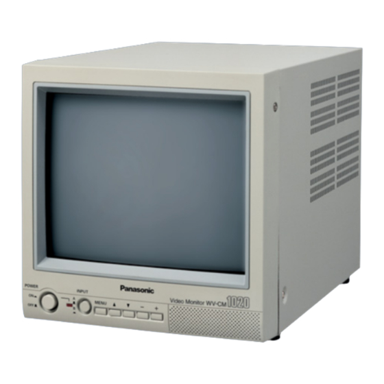
PREFACE The Panasonic‘s Video Monitor WV-CM1020 produces sharp color pictures and audio output. FEATURES • Approx. 223 mm (8-3/4” inches) actual diagonal visual size. • A or B channel selectable for input and output signals. • Looped through BNC connectors for video inputs and outputs. -
Page 4: Major Operating Controls And Their Functions
MAJOR OPERATING CONTROLS AND THEIR FUNCTIONS POWER INPUT MENU q Power Switch (POWER, ON/OFF) This is a push-push type switch which turns the power of this monitor on and off. Press once (switch remains down (;)) to turn on the power of the monitor. -
Page 5: Cable Informations
!1 Video A input Connector (VIDEO A IN) For input of the NTSC composite video signal from an outboard device. !2 Video A output Connector (VIDEO A OUT) The video input signal connected to the video input connector !1 is looped through to this connector and terminated automatically. -
Page 6: System Connection
SYSTEM CONNECTION Single Monitor Connection Connecting Cameras 1. Connect the Video Output terminal of the camera to the Video Input Connector A or B of the monitor with a 75- ohm coaxial cable. Note: Keep the Power Switch in the OFF position before connecting the camera. -
Page 7: Advanced Control Operation
ADVANCED CONTROL OPERATION Displaying the Setup Menu 1. Press the power switch once (switch remains down (;)) to turn on the power of the monitor. 2. Power Indicator is on. 3. Select the input channel by pressing the input signal select switch. Press the MENU button to open the setup menu. -
Page 8: Specifications
7. To reset the monitor to the default settings, move the cursor to NORMAL SETTINGS by pressing the (D) or (C) button. Then press the (–) or (+) button to restore the factory default settings. BRIGHT CONTRAST PICTURE COLOR TINT LANGUAGE NORMAL SETTINGS BRIGHT... - Page 9 Panasonic Security and Digital Imaging Company A Division of Matsushita Electric Corporation of America Executive Office: One Panasonic Way 3E-7, Secaucus, New Jersey 07094 Regional Offices: Northeast: One Panasonic Way, Secaucus, NJ 07094 (201) 348-7303 Southern: 1225 Northbrook Parkway, Suite 1-160, Suwanee, GA 30024 (770) 338-6838...