Table of Contents
Advertisement
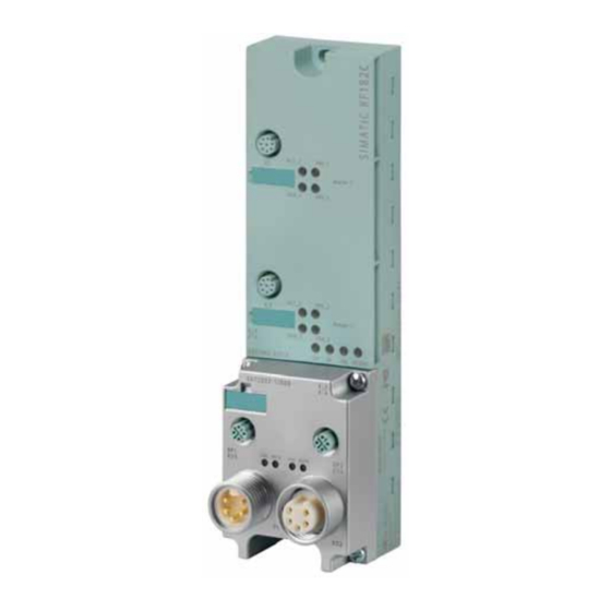
RF182C communication module
SIMATIC Sensors
RFID systems
RF182C communication module
Operating Instructions
10/2010
J31069-D0204-U001-A2-7618
___________________
Introduction
___________________
Description
___________________
Mounting
___________________
Connecting
___________________
Parameterizing
___________________
Communication interface
___________________
Maintenance and Service
___________________
Diagnostics
___________________
Error messages
___________________
Examples/applications
___________________
Technical data
___________________
Dimension drawings
Connecting cable to the
___________________
reader/SLG
___________________
Ordering data
Command and
___________________
acknowledgement telegrams
___________________
Addressing of the RFID tags
Transfer scheme for
___________
hexadecimal tag data via
XML
___________________
Service & support
1
2
3
4
5
6
7
8
9
10
11
12
13
14
A
B
C
D
Advertisement
Table of Contents

Related Manuals for Siemens RF182C


Summary of Contents for Siemens RF182C
- Page 1 ___________________ RF182C communication module Introduction ___________________ Description ___________________ Mounting ___________________ Connecting SIMATIC Sensors ___________________ Parameterizing ___________________ RFID systems Communication interface RF182C communication module ___________________ Maintenance and Service ___________________ Diagnostics Operating Instructions ___________________ Error messages ___________________ Examples/applications ___________________ Technical data ___________________...
- Page 2 Note the following: WARNING Siemens products may only be used for the applications described in the catalog and in the relevant technical documentation. If products and components from other manufacturers are used, these must be recommended or approved by Siemens. Proper transport, storage, installation, assembly, commissioning, operation and maintenance are required to ensure that the products operate safely and without any problems.
-
Page 3: Table Of Contents
Wiring connection block M12, 7/8"....................24 Wiring of the push-pull connection block ..................27 Loop-through of Ethernet and supply voltage................30 Wiring an RF182C to a controller with Ethernet connection............32 Connecting the RF182C to functional ground (PE) ..............33 Parameterizing ............................35 Address assignment for Ethernet....................35 Data communication between client and RF182C...............37... - Page 4 Example application for a PLC according to DIN IEC 61131............99 Technical data ............................101 Dimension drawings ..........................103 12.1 Dimension drawing for RF182C with fixing holes ..............103 Connecting cable to the reader/SLG...................... 105 13.1 Routing of standard cables ....................... 105 13.2...
-
Page 5: Introduction
Introduction Introduction Purpose of these operating instructions The information provided in these Operating Instructions enables you to operate the RF182C communication module on a standard PC or a PLC. Basic knowledge required These operating instructions assume general knowledge of automation engineering and identification systems. - Page 6 Introduction 1.1 Introduction Recycling and disposal ● Due to its environmentally compatible equipment, the RF182C communication module can be recycled. ● Contact a certified electronic-waste disposal company to recycle and dispose of your old equipment in an environment-friendly manner. RF182C communication module...
-
Page 7: Description
● MOBY U Features Up to 2 readers/SLGs can be operated on the RF182C at the same time. The user can issue a command on 2 readers/SLGs simultaneously. The tag data is accessed by means of physical addressing of the tag. - Page 8 ● Module supports SNMP Layout The RF182C has the same enclosure as the RFID communication module ASM 456 for PROFIBUS and the RFID communication module RF180C for PROFINET. For connecting to Ethernet, the RF182C communication module features a connection block in one of the following designs: ●...
- Page 9 Description The following figure shows the basic design of the RF182C. Figure 2-1 Basic design of the RF182C RF182C communication module Operating Instructions, 10/2010...
- Page 10 Description Potential Ungrounded installation of a system is possible with the RF182C. The following circuit shows the internal relationships of the reference potentials. Figure 2-2 Galvanic isolation of RF182C RF182C communication module Operating Instructions, 10/2010...
- Page 11 Description Integration The following figure shows how the RF182C with connection block M12, 7/8'' is integrated in an automation system. The push-pull connection block is integrated in the same manner as the connection block M12, 7/8''. PROFINET IO Master module...
- Page 12 Description RF182C communication module Operating Instructions, 10/2010...
-
Page 13: Mounting
The RF182C communication module is designed for easy assembly. Mounting position, mounting dimensions Mounting position There are no restrictions regarding the mounting position for the RF182C. Mounting dimensions and spacing Table 3- 1 Mounting dimensions of base module with connection block M12, 7/8'' (without... -
Page 14: Mounting The I/O Module
Note Functional ground (PE) If a grounded metal mounting surface is used, the bottom mounting screw of the RF182C module already establishes a reliable grounding connection. This eliminates the need for a separate grounding cable. If you use the fixing screw as grounding connection, the thread of the fixing screw or the contact facing of the fastening nut on the base must be unpainted. - Page 15 Fix the base unit onto a level surface using the screws. The base unit must be screwed to the surface (3 Nm tightening torque) at both fixing points (front, top and bottom). Figure 3-1 Mounting the I/O module RF182C communication module Operating Instructions, 10/2010...
-
Page 16: Mounting The Connection Block
Mounting 3.3 Mounting the connection block Mounting the connection block Features The connection block connects the RF182C with the Ethernet and supplies the base unit with voltage. Requirements The base unit is already mounted Required tools Cross-head screwdriver, medium. Mounting the connection block 1. - Page 17 Figure 3-3 Plug the push-pull connection block onto the base unit and screw it on Note IP65, IP66 or IP67 degree of protection only exists when the connection block is screwed to the base unit. RF182C communication module Operating Instructions, 10/2010...
-
Page 18: Replacing Labels
1. Push the screwdriver into the small opening of the label, and then lever it out. Figure 3-4 Removing labels 2. With your finger push the new label into the holder of the module. RF182C communication module Operating Instructions, 10/2010... -
Page 19: Disassembling The Rf182C
Procedure The RF182C is wired up and operating. 1. Switch off the supply voltage for the RF182C. 2. Disconnect the wiring on the connection block. 3. Remove the 4 fixing screws from the connection block and pull the connection block off the base unit. - Page 20 Mounting 3.5 Disassembling the RF182C RF182C communication module Operating Instructions, 10/2010...
-
Page 21: Connecting
Connecting Proper use When connecting non-specified devices to the RF182C, it is possible that the connected device may be destroyed. NOTICE The device must not be connected to the public telephone network without a HUB / Switch because the voltage intervals are designed for 500 V. - Page 22 Connecting PROFINET IO Master module SIMATIC S7 Figure 4-2 RF182C with STAR topology RF182C communication module Operating Instructions, 10/2010...
- Page 23 Connecting Reader/SLG connection system One reader/SLG always occupies one M12 connection socket on the RF182C. A pre- assembled cable therefore provides the optimum easy connection for the reader/SLG. The connection cable is 2 m long in the standard version. PROFINET IO...
-
Page 24: Wiring Connection Block M12, 7/8
Data line TxP Data line RxP Data line RxP Data line TxP Data line TxN Data line RxN Data line RxN Data line TxN Any connector can be used for infeed and looping through RF182C communication module Operating Instructions, 10/2010... - Page 25 (wiring side) Load voltage ground (2M) Ground for electronics/encoder supply (1M) Functional ground (PE) Electronics/encoder supply (1L+) (voltage supply for RF182C and reader/SLG) Load voltage supply (2L+) (unused on RF182C) Table 4- 3 Pin assignment of 7/8" connector, 4-pole (supply voltages) Assignment View of 7/8"...
- Page 26 Sealing unused sockets Always close all unused sockets using M12 or 7/8" seal caps in order to achieve the degree of protection IP65, IP66 or IP67. See section Ordering data (Page 109) for order numbers. RF182C communication module Operating Instructions, 10/2010...
-
Page 27: Wiring Of The Push-Pull Connection Block
– 5-core cable and push-pull cable connector for 1L+/2L+ – 4-core, shielded cable (bus cable) and push-pull cable connector for RJ45 Note Refer to the manufacturer's documentation if you are fabricating the cables with the push-pull cable connectors. RF182C communication module Operating Instructions, 10/2010... - Page 28 X01 DC 24 V for infeed X02 24 V DC for looping through Electronic/encoder supply 1L+ground Ground for electronic/encoder supply 2L+ load voltage supply Ground for load voltage supply 2M Functional ground (PE) RF182C communication module Operating Instructions, 10/2010...
- Page 29 Figure 4-5 Connecting push-pull cable connectors Sealing unused sockets Cover all unused push-pull sockets with caps in order to achieve degree of protection IP65, Ordering data IP66, or IP67. Refer to section for order numbers. RF182C communication module Operating Instructions, 10/2010...
-
Page 30: Loop-Through Of Ethernet And Supply Voltage
Data communication to subsequent devices will be interrupted from this module onwards. Figure 4-6 Loop-through of Ethernet and supply voltage CAUTION The IP65, IP66 or IP67 degree of protection is no longer guaranteed when the connection block is dismounted. RF182C communication module Operating Instructions, 10/2010... - Page 31 Notes for wiring ● If you are wiring your structure, then you must take into account the impact of cable length on supply voltage to the RF182C. Example: When using a 10 m long cable with a diameter of 1.5 mm , the voltage drop is 2.5 V with...
-
Page 32: Wiring An Rf182C To A Controller With Ethernet Connection
Connecting 4.4 Wiring an RF182C to a controller with Ethernet connection Wiring an RF182C to a controller with Ethernet connection A connection from Ethernet to an M12 connection can be easily implemented. Self-assembly of an Ethernet M12 cable ● You will need a pre-assembled PROFINET/Ethernet cable with M12 connectors at both ends twice the required length. -
Page 33: Connecting The Rf182C To Functional Ground (Pe)
Connecting the RF182C to functional ground (PE) Features ● You have to connect the RF182C to the functional ground (PE). For this purpose, a grounding screw for one grounding cable is provided on the communication module. ● If a grounded metal mounting surface is used, the bottom mounting screw of the RF182C module already establishes a reliable grounding connection. - Page 34 Connecting 4.5 Connecting the RF182C to functional ground (PE) Connecting the RF182C to functional ground (PE) Standard grounding via the fixing screw Optional grounding via a grounding cable 1. Mount the module on the grounded, metallic base as 1. Isolate the grounding cable and secure the cable lug.
-
Page 35: Parameterizing
An IP address may be present only once within a network. It must be parameterized in the RF182C. In the user application in the PC, the IP address is specified when establishing a connection. - Page 36 Port assignment via web server The assignment of the ports can be changed via the web server. If no connection could be established with the RF182C, check the port setting via the web server. The default port setting is: 10001/10002.
-
Page 37: Data Communication Between Client And Rf182C
(Page 41). ● Optionally, a configuration message frame (comDevSetConfig) can be sent to the RF182C to change the communication mode stored in the RF182C by default. The client that configures the RF182C first also defines the RF182C settings. Further configurations during operation are not possible. The module must be de- energized or restarted by means of a "Reset"... - Page 38 5.2 Data communication between client and RF182C ● If no configuration message frame is sent and the default port setting was not changed via the web server, the RF182C is operated in the default setting. The default values are shown in the following figure:...
- Page 39 If, in case of an error, no response is sent in answer to the heartbeat message frame from the RF182C, the client must then initiate further actions (disconnect/connect/parameterize the reader).
-
Page 40: Factory Setting Of The Rf182C
Therefore, you must first assign the IP address data (IP address and subnet mask) to the RF182C so that it can be used in the Ethernet network. An IP address can be assigned to the RF182C using the PST tool or via the web server. -
Page 41: Assigning The Ip Address
Assigning the IP address 5.4.1 Overview There are two ways of assigning an IP address to the RF182C communication module: ● Using the "Primary Setup Tool V4-0" ● Via the web server of the communication module Both alternative procedures are described in brief below. - Page 42 No contact with web server RF182C If the web server of the communication module does not open, you should make sure that all cables are correctly connected and check whether the RF182C communication module has powered up. 2. Check the IP address of the PC and the address of the subnet mask in the "Communication"...
- Page 43 Parameterizing 5.4 Assigning the IP address 3. In the "Settings" tab you will find the settings that are currently valid on the RF182C device. Here you can change the IP address, subnet mask, default router or the port numbers of the individual readers.
- Page 44 5.4 Assigning the IP address Resetting to factory settings Via the "Reset" menu, you can reset all settings to the factory settings. 1. To do this, click on the button "Reset RF182C to factory settings". Note Soft reset If serious communication errors occur, you can also execute a so-called "soft reset" using the "Reset 182C"...
-
Page 45: Primary Setup Tool
A window opens that indicates that a device was found in the network. If no RF182C communication module is shown, make sure that all cables are connected properly and check if the RF182C communication module has started. Check the IP address of the PC and the subnet mask. - Page 46 – If you want to change the data under "Assign IP Parameters", check the adjacent option. – Click the button "Assign Name" to explicitly assign a name to the device, e.g. RF182C. 4. If you want to transfer the changed data to the communication module, select the higher- level folder and select "Module >...
- Page 47 You can now address the device using a browser or user program. Note IP address stored on connection block The IP address is stored on the connection block. Therefore, if you replace the base module, no new IP address has to be assigned. RF182C communication module Operating Instructions, 10/2010...
-
Page 48: Troubleshooting: Assigning The Ip Address
Do not switch on the RF182C communication module yet. 2. Remove all other network cables from your PC/notebook and make sure that the RF182C is the only network device connected to your PC/notebook. -
Page 49: Communication Interface
The structure of the XML commands of this section can also be found in a text file (RF182C_XML_Commands.txt). You can find this file on the RFID CD "Software & Documentation". Follow the link "CM > ASM > RF182C > Tools". Thus you can transfer the basic structure of the commands to your application program by means of copy and paste. -
Page 50: Configuration Parameters Of The Rf182C
Communication interface 6.2 Configuration parameters of the RF182C Configuration parameters of the RF182C The RF182C is already configured at the factory. In most cases this command can therefore be omitted in the application. XML command <command> <comDevSetConfig> <signature>RF182C</signature> <protocolVersion>Version</protocolVersion> <parameter>... - Page 51 Communication interface 6.2 Configuration parameters of the RF182C Parameter Parameter Data type Values Version ASCII 0 ... 9, A ... Z Here you must enter the following version of the protocol as string: V1.0 • RF182C ASCII Here you must enter the following values: RF182C •...
-
Page 52: Input Parameters Of The Rf182C
Input parameters of the RF182C The RESET command is always required after switching on/run-up of the module. It contains the settings for the reader connected to the RF182C. Below the XML command for the RESET command is described: XML command <command>... -
Page 53: Commands Of The Communication Module
MOBY System Manual or Appendix B Addressing of the RFID tags (Page 123). Data ASCII hex 00...FF (ASCII string (max. 128 KB ASCII)) User data to be written to the tag. • RF182C communication module Operating Instructions, 10/2010... -
Page 54: Readtagdata
The contents of Datalength refer to the number of bytes to be read from the tag. Twice the number of characters is transmitted in the "Data" field of the XML response. Data ASCII hex max. 128 KB ASCII per command RF182C communication module Operating Instructions, 10/2010... -
Page 55: Initializetag
MOBY System Manual or Appendix B Addressing of the RFID tags (Page 123). Value ASCII hex 00 ... FF (2 x ASCII) Hex value that is written to the tag. • RF182C communication module Operating Instructions, 10/2010... -
Page 56: Getreaderstatus
An acknowledgment message frame on the reader status is returned via the "Data" parameter. Different acknowledgment message frames are returned depending on the set "mode". All available acknowledgment message frames can be found in section Command and acknowledgement telegrams (Page 111). RF182C communication module Operating Instructions, 10/2010... -
Page 57: Gettagstatus
04 = RF600: Diagnostic data Week ASCII hex 00 ... FF (2 x ASCII) Year ASCII hex 00 ... FF (2 x ASCII) Data ASCII hex 0000 ... FFFF (ASCII string: max. 400 x ASCII) RF182C communication module Operating Instructions, 10/2010... -
Page 58: Setant
00 = Antenna 1 off and Antenna 2 off 01 = Antenna 1 on and Antenna 2 off 02 = Antenna 1 off and Antenna 2 on 03 = Antenna 1 and 2 on RF182C communication module Operating Instructions, 10/2010... -
Page 59: Heartbeat
Below the XML command for monitoring the connection (heartbeat) is described: XML command <command> <heartbeat/> </command> XML response Below is the XML response without error entry <reply> <resultCode>0000</resultCode> <heartbeat/> </reply> See also Error messages (Page 71) RF182C communication module Operating Instructions, 10/2010... -
Page 60: Asynchronous Message Frames
0000 ... FFFF (4 x ASCII) The sequence number is a number that is automatically set to 0000 after switching on the RF182C. After sending a notification on the same TCPIP channel, the sequence number is increased by 1. After FFFF, this number is also set to 0000 again. -
Page 61: Alarm
Communication interface 6.5 Asynchronous message frames 6.5.2 alarm If no command is pending, the RF182C communication module sends an alarm. XML message frame <alarm> <id>Sequencenumber</id> <origin>Origin</origin> <deviceName>Devicename</deviceName> <deviceTime>Time</deviceTime> <content> <code>Errorcode</code> </content> </alarm> Parameter Parameter Data type Values Sequence number ASCII hex 0000 ... - Page 62 Communication interface 6.5 Asynchronous message frames RF182C communication module Operating Instructions, 10/2010...
-
Page 63: Maintenance And Service
RF182C communication module is included in the data communication by the Ethernet controller. Note If the connection block is replaced in addition to the base unit, the RF182C may not start up automatically. In this case, proceed as follows: RF182C communication module... - Page 64 What should I do if the RF182C can no longer be addressed If the connection block is replaced in addition to the base unit, it is possible that the RF182C can no longer be addressed. This is indicated by a permanently lit or flashing BF LED.
-
Page 65: Firmware Update
Maintenance and Service 7.2 Firmware update Firmware update The firmware for the RF182C communication module can be updated via the Ethernet interface. You can the start the firmware update via the web server of the communication module. Preconditions ● The communication module is connected to the PC via Ethernet. - Page 66 Maintenance and Service 7.3 Reader update RF182C communication module Operating Instructions, 10/2010...
-
Page 67: Diagnostics
Diagnostics Diagnostics using LEDs The following figure shows details of the LEDs of the RF182C. With connection block M12, 7/8'' With push-pull connection block RF182C communication module Operating Instructions, 10/2010... - Page 68 LEDs Meaning Lights up when the RF182C has completed start-up without errors. 24 V DC Lights up when the 24 V supply voltage is connected to the RF182C. ACT_1, ACT_2 Reserved ERR_1, ERR_2 A flashing pattern indicates the last error to occur. These flashing patterns are described in Section Error messages (Page 71).
- Page 69 Internal fault Checksum error of the firmware Slow Slow Firmware update flashin flashin (flashes with every described area) Flashe Flashe Flashe Run-up cannot be parameterized. No client has connected. acc. to acc. to table table RF182C communication module Operating Instructions, 10/2010...
- Page 70 Diagnostics 8.1 Diagnostics using LEDs RF182C communication module Operating Instructions, 10/2010...
-
Page 71: Error Messages
Below the XML response with error entry is described: XML response <reply> <resultCode>Errorcode</resultCode> <Name of the output command, e.g. reset/> </reply> The following table describes the possible error codes (resultCodes). The error codes are coded in 4 bytes. RF182C communication module Operating Instructions, 10/2010... -
Page 72: Error Messages Of The Rf182C
Error messages 9.3 Error messages of the RF182C Error messages of the RF182C Table 9- 1 Error messages of the RF182C via the "resultCode" variable Error code Flashing of Description ERR LED ASCII hex 0000 – No error Default value if everything is ok. - Page 73 Error messages 9.3 Error messages of the RF182C Error code Flashing of Description ERR LED ASCII hex 0005 Unknown command The client is sending an uninterpretable command to the communication module. Check the XML command • The MDS reported an address error •...
- Page 74 Error messages 9.3 Error messages of the RF182C Error code Flashing of Description ERR LED ASCII hex 000E ECC error (only possible when ECC_mode = TRUE) The data could not be read by the MDS. Data of the MDS have been lost (MDS defective).
- Page 75 Error messages 9.3 Error messages of the RF182C Error code Flashing of Description ERR LED ASCII hex 0019 Previous command is active or buffer overflow The user sent a new command to the communication module although the last command was still active.
- Page 76 Error messages 9.3 Error messages of the RF182C Table 9- 2 Error messages of the RF182C Error code Flashing of Description ERR LED 3214 Fatal Error. Internal firmware error of the communication module Turn the power supply of the communication module off and on again •...
- Page 77 Error messages 9.3 Error messages of the RF182C Error code Flashing of Description ERR LED 3424 Error when receiving the TCP channel Connection was aborted • TCP/IP protocol error • Permissible number of connections at one port was exceeded •...
-
Page 78: Diagnostics Via Web Server
Save data records Via the "Identification" menu in the "Settings" tab, various settings can be made and stored on the communication module. Use the "transmit and save" button to save the settings. RF182C communication module Operating Instructions, 10/2010... -
Page 79: Communication Status Query
"Readout" tab. 9.4.2 Communication status query You can query the communication status of the RF182C communication module via the menu "Communication" in the Connection "tab". You can see the status of the user connection. RF182C communication module... -
Page 80: Event And Message Frame Overview
Via the "Diagnostic" menu in the "Events " tab, you can query the events of the module. Message frame overview Via the "Diagnostic" menu in the "Traffic " tab, you can query the last twenty message frames of the communication module. RF182C communication module Operating Instructions, 10/2010... -
Page 81: Examples/Applications
● Sockets are used by many programming languages (e.g. C, C++, C#, Delphi, VB, Java). Other programming languages must be considered with regard to the usability of network programs. RF182C communication module Operating Instructions, 10/2010... -
Page 82: Basic Client/Server Principle
Receiving data Close() Closing the socket after completing data transmission. When working with the RF182C, a Close usually only occurs when the system is shut down. Note No parameters or return values of the individual functions are listed here since they may differ in the different operating systems/programming languages. -
Page 83: Partial Programming Example Of A Client In C/Windows Operating System
// Assignment of port number:10001 adr.sin_addr.s_addr = // Assignment of IP address: 192.168.0.100 /* Creation of a socket – function returns the handle from the socket SOCK_STREAM – connection-oriented protocol TCP*/ Client = socket( AF_INET, SOCK_STREAM, 0 ); RF182C communication module Operating Instructions, 10/2010... -
Page 84: Sending Data
> 0 ) // Data was received // The data can be read in the caBuf array else // Error occurred while receiving // Connection termination if applicable /*Close connection*/ closesocket( Client ); RF182C communication module Operating Instructions, 10/2010... -
Page 85: Rf182C User Application
PC in your development environment. This application can be used as a basis for your application. You can find the application on the RFID CD "Software&Documentation", Edition 2009 or later. On the user interface, follow the link "CM/ASM > RF182C > Demo". You can start the program directly. Requirements ●... -
Page 86: User Interface Layout
Examples/applications 10.2 RF182C user application 10.2.1 User interface layout ① IP address input window ② Port number input window ③ Button for connecting or disconnecting ④ Note: Connected or not connected ⑤ Note: Presence or no presence ⑥ Check box: The output window scrolls automatically or does not scroll automatically ⑦... -
Page 87: Extracts Example Code Of The User Application In C
Examples/applications 10.2 RF182C user application 10.2.2 Extracts example code of the user application in C# using System; using System.Collections.Generic; using System.ComponentModel; using System.Data; using System.Drawing; using System.Text; using System.Windows.Forms; using System.Net; using System.Net.Sockets; using System.Web; namespace RF182CApp public partial class MainForm : Format // Socket to realize TCP/IP connection private Socket Connection = null;... - Page 88 Examples/applications 10.2 RF182C user application SetConnectionState(false); else //not connected --> connect //Try to connect the socket as client. if (Connect() == true) // Connection was established successfully SetConnectionState(true); /* This function enables/disables controls needed to set up * the connection and those needed to communicate separately from * each other.
- Page 89 Examples/applications 10.2 RF182C user application SetTagDetectionState(TagDetectionState.UNDEFINED); //There may be uncollected data in the buffer --> call ParseBuffer() ParseBuffer(); // Visualization Enable(true, false); labelConnectionState.Text = "NOT CONNECTED"; labelConnectionState.BackColor = Color.Red; buttonConnect.Text = "Connect"; AsyncError = false; /* Connects a stream based TCP/IP socket as client. */ private bool Connect() //Collect port and IP from the window.
- Page 90 Examples/applications 10.2 RF182C user application //Start asynchronous receive ReceiveString s = new ReceiveString(); Connection.BeginReceive(s.buffer, 0, ReceiveString.BufferSize, 0, new AsyncCallback(ReceiveCallback), s); return true; catch (Exception ex) MessageBox.Show(ex.Message, "Connecting Failed"); return false; /* This routine is called if there is new data in the asynchronous * receive available.
- Page 91 Examples/applications 10.2 RF182C user application //only do something if there is a message specified if (editMessage.Text != "") // convert to byte array byte[] buffer = Encoding.ASCII.GetBytes(editMessage.Text.ToCharArray()); // Send! int count = Connection.Send(buffer); // Did we send everything? if (count != buffer.Length) MessageBox.Show("Sending failed!");...
- Page 92 Examples/applications 10.2 RF182C user application // (ReceiveCallback is asynchronous) lock (ReceiveBuffer) for (XMLTag tag = FirstTag(); tag != null; tag = FirstTag()) // Extract the parsed message and append it String message = ReceiveBuffer.Substring(tag.startIndex, tag.length); AppendInMessage(message); // Remove parsed message from ReceiveBuffer ReceiveBuffer = ReceiveBuffer.Substring(tag.startIndex + tag.length);...
- Page 93 Examples/applications 10.2 RF182C user application // first tag is a reply endTag = "</reply>"; tag.type = "reply"; tag.startIndex = index1; else if (index2 < index3) // first tag is a notification endTag = "</notification>"; tag.type = "notification"; tag.startIndex = index2;...
- Page 94 Examples/applications 10.2 RF182C user application switch (state) case TagDetectionState.YES: labelTagDetected.Text = "TAG(s) DETECTED"; labelTagDetected.BackColor = Color.Green; break; case TagDetectionState.NO: labelTagDetected.Text = "NO TAG DETECTED"; labelTagDetected.BackColor = Color.Red; break; case TagDetectionState.UNDEFINED: labelTagDetected.Text = ""; labelTagDetected.BackColor = BackColor; //Color of the dialog break;...
-
Page 95: Functions Of The Rf182C Applications
10.2 RF182C user application 10.2.3 Functions of the RF182C applications The following screenshots show the different functions of the RF182C application: Example of working with the application 1. First enter the IP address and port number in the corresponding entry fields. - Page 96 Examples/applications 10.2 RF182C user application 2. Then click "Connect". Figure 10-4 Connected successfully The connection to the RF182C has been established successfully. The send window is empty after sending successfully. RF182C communication module Operating Instructions, 10/2010...
- Page 97 Examples/applications 10.2 RF182C user application 3. Enter a RESET command in the input window. Click the "Send" button. Figure 10-5 RESET command The RF182C communication module operates in default mode. RF182C communication module Operating Instructions, 10/2010...
- Page 98 4. The next window shows that the RESET command has been sent successfully. The RF182C has sent an acknowledgement with the error code "0000" (everything OK). It is indicated that a tag has been detected in the antenna field of the reader (0001).
-
Page 99: Example Application For A Plc According To Din Iec 61131
5. The next window shows that the tag has exited the reader's antenna field again (0000) Figure 10-7 Tag exited the field 10.3 Example application for a PLC according to DIN IEC 61131 In preparation. RF182C communication module Operating Instructions, 10/2010... - Page 100 Examples/applications 10.3 Example application for a PLC according to DIN IEC 61131 RF182C communication module Operating Instructions, 10/2010...
-
Page 101: Technical Data
Maximum infeed current in the push- Up to 40 °C: Up to 60 °C: pull connection block 1L = 12 A 1L = 8 A 2L = 12 A 2L = 8 A Galvanic isolation RF182C communication module Operating Instructions, 10/2010... - Page 102 24 V DC supply: Safety (electrical) isolation of low voltage (SELV / PELV acc. to EN 60950) The power supply must provide the current required (max. 500 mA) during brief power failures of ≤ 20 ms. A cable cross-section of 2.5 mm² is mandatory for an amperage > 8 A. RF182C communication module Operating Instructions, 10/2010...
-
Page 103: Dimension Drawings
Dimension drawings 12.1 Dimension drawing for RF182C with fixing holes Dimension drawing of an RF182C with bus connection block M12, 7/8'' PN PN Figure 12-1 Dimension drawing of an RF182C with bus connection block M12, 7/8'' RF182C communication module Operating Instructions, 10/2010... - Page 104 Dimension drawings 12.1 Dimension drawing for RF182C with fixing holes Dimension drawing of an RF182C with push-pull bus connection block Figure 12-2 Dimension drawing of an RF182C with push-pull bus connection block RF182C communication module Operating Instructions, 10/2010...
-
Page 105: Connecting Cable To The Reader/Slg
Connecting cable M12 ↔ sub-D (MOBY D all SLGs except 6GT2602-0AB10-0AX0) Maximum cable length The RF182C can be operated with any reader/SLG configuration with a maximum cable length of 50 m. Longer connecting cables of up to 1000 m are possible in some instances. The current consumption of the connected reader/SLG must however be taken into account. - Page 106 Table 13- 3 Connecting cable M12 ↔ sub-D 9-pin M12 connector (male) Sub-D connector (female) – – 1, 8 Note: Reader/SLG with Sub-D connector must be supplied over an additional connector with 24 V DC. RF182C communication module Operating Instructions, 10/2010...
-
Page 107: Self-Assembled Cable
The pin assignment is listed in the following table. Table 13- 4 Pin assignment M12 connector (male) Signal Core color 1L+ (+ 24 V) Note data sheet provided by cable −RxD manufacturer −TxD Free Functional ground (PE)/shield RF182C communication module Operating Instructions, 10/2010... - Page 108 Connecting cable to the reader/SLG 13.2 Self-assembled cable RF182C communication module Operating Instructions, 10/2010...
-
Page 109: Ordering Data
Ordering data Table 14- 1 RF182C ordering data and accessories RF182C RF182C communication module 6GT2002-0JD10 max. 2 SLGs or readers can be connected Connection block M12, 7/8'' (5-pole) 6GT2002-1JD00 Connection block M12, 7/8'' (4-pole) 6GT2002-4JD00 Push-pull connection block, RJ45 6GT2002-2JD00... - Page 110 6GT2891-0FN50 50 m Reader cable for RF300; connector on the reader is angled; 2 m 6GT2891-0JH20 RFID CD "Software&Documentation" 6GT2080-2AA10 These cables are available in different lengths. See Catalog IK PI for more details RF182C communication module Operating Instructions, 10/2010...
-
Page 111: Command And Acknowledgement Telegrams
Communication interface (Page 49). Only those commands requiring a special coding of commands and results are described. Note Special information on telegram expansions for the RF620R/RF630R readers can be found in the Appendix of the "Configuration Manual RF620R/RF630R". RF182C communication module Operating Instructions, 10/2010... - Page 112 Command and acknowledgement telegrams RESET RF182C communication module Operating Instructions, 10/2010...
- Page 113 Semaphore control (synchronization with reader (RF300: res) Status of antenna stand_by Time of standby after command execution (RF300: res) MDS control Presence mode For detailed information, please refer to the respective reader description. RF182C communication module Operating Instructions, 10/2010...
- Page 114 Command and acknowledgement telegrams GetReaderStatus mode = 02 GetReaderStatus mode = 03 GetReaderStatus mode = 04 GetReaderStatus mode = 05 RF182C communication module Operating Instructions, 10/2010...
- Page 115 Reader status mode information = 06 Error counter, passive (errors during idle time) Abort counter Code error counter Signature error counter CRCFZ CRC error counter BSTAT Current command status ASMFZ Interface error counter for ASM res. Spare RF182C communication module Operating Instructions, 10/2010...
- Page 116 Multitag reader field_on_control Set communication type field_on_time Set channel expert Expert mode Status of antenna scanning_time Radio communication profile MDS control Presence mode For detailed information, please refer to the respective reader description. RF182C communication module Operating Instructions, 10/2010...
- Page 117 Date of last sleep-time change (week of year) Year Date of last sleep-time change (year) battery Battery left (percentage) Set sleep-time value on MDS For detailed information, please refer to the respective reader description. RF182C communication module Operating Instructions, 10/2010...
- Page 118 Tag status mode information = 01 UID 1 4 UID (tag number, EPC ID) UID 5 8 Lock_state EEPROM write protection status res. Spare For detailed information, please refer to the respective reader description. RF182C communication module Operating Instructions, 10/2010...
- Page 119 UID (tag number, EPC ID) UID 5 8 Relationship between power flow density limit and actual measured value Error counter, passive (errors during idle time) Error counter, active (errors during communication) ANWZ Presence error res. Spare RF182C communication module Operating Instructions, 10/2010...
- Page 120 Lock status, OTP information: per block (4x4 bytes or 2x8 bytes) one bit (bit=1: block is locked) block_size Block size of the transponder nr_of_blocks Number of blocks For detailed information, please refer to the respective reader description. RF182C communication module Operating Instructions, 10/2010...
- Page 121 UID (tag number, EPC ID) UID 5 8 Antenna that has detected the MDS RSSI RSSI threshold value hours Min. Minutes Seconds Spare res1 Spare res2 Spare For detailed information, please refer to the respective reader description. RF182C communication module Operating Instructions, 10/2010...
- Page 122 Command and acknowledgement telegrams RF182C communication module Operating Instructions, 10/2010...
-
Page 123: Addressing Of The Rfid Tags
ID No.: (4 fixed-coded bytes; can only be read with the MDS status command) Address space of the MDS versions for MOBY D For address space of the RF300 transponders, see MOBY D System Manual (http://support.automation.siemens.com/WW/view/en/13628689/0/en), section "Mobile data storage units > Introduction". Address space of the transponder versions for RF300 For address space of the RF300 transponders, see SIMATIC RF300 System Manual (http://support.automation.siemens.com/WW/view/en/21738946/0/en), section "RF300... - Page 124 Addressing of the RFID tags Address space of the transponder versions for RF600 For address space of the RF600 transponders, see SIMATIC RF620R/RF630R Parameterization Manual (http://support.automation.siemens.com/WW/view/de/33287195/0/en), section "Examples/applications > Memory configuration". RF182C communication module Operating Instructions, 10/2010...
-
Page 125: Transfer Scheme For Hexadecimal Tag Data Via Xml
The following example shows the coding scheme: Command to RF182C <readTagData> <startAddress>0000</startAddress> <dataLength>0004</dataLength> </readTagData> Data in tag Address Data Data [hex] [hex] [ADC] 0000 0001 0002 0003 Result of the RF182C <readTagData> <returnValue> <data>4D4F4259</data> </returnValue> </readTagDatat> RF182C communication module Operating Instructions, 10/2010... - Page 126 Transfer scheme for hexadecimal tag data via XML Optional: storage of the result data in the data block of a controller Address Data Data [dec] [hex] [ASC] RF182C communication module Operating Instructions, 10/2010...
-
Page 127: Service & Support
You can send a support query to: Online support request form: (www.siemens.com/automation/support-request) General information on new features of the RF182C communication module and an overview of our other identification systems can be found on the Internet at: RFID homepage (www.siemens.com/simatic-sensors/rf) - Page 128 Service & support RF182C communication module Operating Instructions, 10/2010...