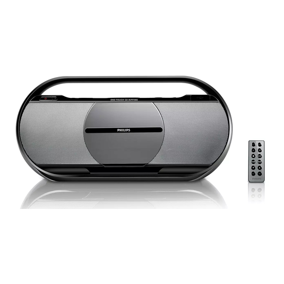
Philips AZ1880 Service Manual
Usb cd soundmachine
Hide thumbs
Also See for AZ1880:
- Quick start manual (1 page) ,
- User manual (18 pages) ,
- Service manual (20 pages)
Table of Contents
Advertisement
Quick Links
USB CD Soundmachine
CONTENTS
Disassembly diagram.....................................................................5-1
Main board
Circuit diagram ..................................................................6-1..6-4
Layout diagram ..................................................................6-5..6-6
MCU board
Circuit diagram .........................................................................7-1
Layout diagram ..................................................................7-2..7-3
Display board
Circuit diagram .........................................................................8-1
Layout diagram .........................................................................8-2
Jack board
Circuit diagram .........................................................................9-1
Layout diagram ..................................................................9-2..9-5
Exploded view diagram ...............................................................10-1
Service parts list .......................................................................... 11-1
©
Copyright 2009 Philips Consumer Electronics B.V. Eindhoven, The Netherlands
All rights reserved. No part of this publication may be reproduced, stored in a retrieval
system or transmitted, in any form or by any means, electronic, mechanical, photocopying,
or otherwise without the prior permission of Philips.
Published by LX 0911 Service Audio
Version 1.0
Subject to modification
AZ1880
-/12
3141 785 33710
Advertisement
Table of Contents

Summary of Contents for Philips AZ1880
-
Page 1: Table Of Contents
Service parts list ................11-1 © Copyright 2009 Philips Consumer Electronics B.V. Eindhoven, The Netherlands All rights reserved. No part of this publication may be reproduced, stored in a retrieval system or transmitted, in any form or by any means, electronic, mechanical, photocopying, or otherwise without the prior permission of Philips. - Page 3 CIRCUIT DIAGRAM - MAIN BOARD PART 1...
- Page 4 CIRCUIT DIAGRAM - MAIN BOARD PART 2...
- Page 5 CIRCUIT DIAGRAM - MAIN BOARD PART 3...
- Page 6 CIRCUIT DIAGRAM - MAIN BOARD PART 4...
- Page 7 LAYOUT DIAGRAM - MAIN BOARD TOP SIDE...
- Page 8 LAYOUT DIAGRAM - MAIN BOARD BOTTOM SIDE...
-
Page 9: Circuit Diagram
CIRCUIT DIAGRAM - MCU BOARD... -
Page 10: Layout Diagram
LAYOUT DIAGRAM - MCU BOARD TOP SIDE... - Page 11 LAYOUT DIAGRAM - MCU BOARD BOTTOM SIDE...
-
Page 12: Circuit Diagram
CIRCUIT DIAGRAM - DISPLAY BOARD... -
Page 13: Layout Diagram
LAYOUT DIAGRAM - DISPLAY BOARD... -
Page 14: Circuit Diagram
CIRCUIT DIAGRAM - JACK BOARD&POWER SWITCH BOARD... -
Page 15: Layout Diagram
LAYOUT DIAGRAM - DC JACK BOARD... -
Page 16: Layout Diagram
LAYOUT DIAGRAM - USB JACK BOARD... - Page 17 LAYOUT DIAGRAM - HEADPHONE JACK BOARD...
- Page 18 LAYOUT DIAGRAM - POWER SWITCH BOARD...
-
Page 19: Exploded View Diagram
10-1 10-1 SET EXPLODED VIEW DIAGRAM... -
Page 20: Service Parts List
11 - 1 Service parts list 0007 996510022421 REMOTE CONTROL 0080 994000005085 CD MECHANISM DA11B3VZ (BALL) 0114 996510022422 CD DOOR SPRING 0204 996510022426 BATTERY DOOR 0208 996510022423 CD DOOR 0210 996510029726 SCREW HOLE COVER 0211 994000001295 DAMPER GEAR ASS'Y J005 996510002103 CONN.

