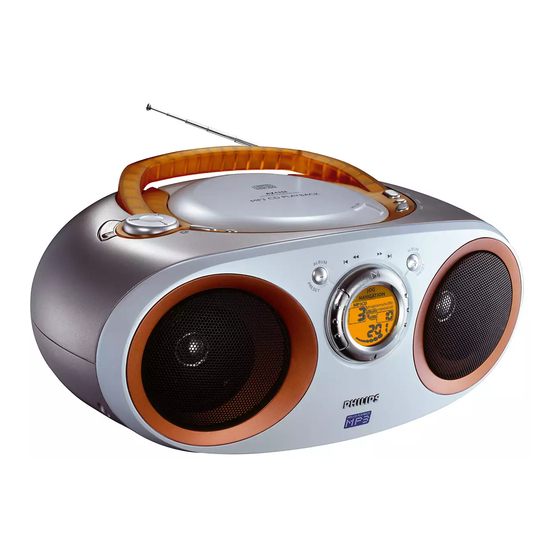
Philips AZ1150 Service Manual
Mp3-cd soundmachine
Hide thumbs
Also See for AZ1150:
- Manual (20 pages) ,
- Manuale utente (17 pages) ,
- Specifications (1 page)
Table of Contents
Advertisement
Quick Links
MP3-CD Soundmachine
TABLE OF CONTENTS
Handling chip components ............................................................1-1
Technical specification...................................................................1-2
Service tools ..................................................................................1-2
Service measurement setup ..........................................................1-3
Connections and controls ......................................................2-1...2-2
Disassembly diagram ....................................................................3-1
Service Test Program ....................................................................4-1
Pin description of ICs.............................................................4-2...4-3
Set block diagram ..........................................................................5-1
Set wiring diagram .........................................................................5-2
KEY BOARD
circuit diagram ..........................................................................6-1
layout diagram ..........................................................................6-1
FRONT BOARD
circuit diagram ..........................................................................7-1
layout diagram ..........................................................................7-2
FEATURE BOARD
circuit diagram ..........................................................................8-1
layout diagram ..........................................................................8-2
TUNER BOARD
circuit diagram ..........................................................................9-1
layout diagram ..........................................................................9-2
tuner adjustment table ..............................................................9-2
©
Copyright 2001 Philips Consumer Electronics B.V. Eindhoven, The Netherlands
All rights reserved. No part of this publication may be reproduced, stored in a retrieval
system or transmitted, in any form or by any means, electronic, mechanical, photocopying,
or otherwise without the prior permission of Philips.
Published by YT 0141 Service Audio
Printed in The Netherlands
Subject to modification
CD99/MP3 BOARD
circuit diagram I ......................................................................10-1
circuit diagram II .....................................................................10-3
layout diagram ........................................................................10-4
MP3 DECODER BOARD
circuit diagram ........................................................................11-1
layout diagram ........................................................................11-2
AMPLIFIER BOARD
circuit diagram ........................................................................12-1
layout diagram ........................................................................12-2
SUPPLY BOARD
circuit diagram ........................................................................13-1
layout diagram ........................................................................13-2
Exploded view..............................................................................14-1
Mechanical partslist .....................................................................14-2
Electrical partslist.............................................................15-1...15-11
AZ1150
AZ1155
all versions
CLASS 1
LASER PRODUCT
© 3140 785 22691
Advertisement
Table of Contents

Related Manuals for Philips AZ1150


Summary of Contents for Philips AZ1150
- Page 1 LASER PRODUCT © Copyright 2001 Philips Consumer Electronics B.V. Eindhoven, The Netherlands All rights reserved. No part of this publication may be reproduced, stored in a retrieval system or transmitted, in any form or by any means, electronic, mechanical, photocopying, or otherwise without the prior permission of Philips.
-
Page 2: Handling Chip Components
HANDLING CHIP COMPONENTS © ñ WARNING WAARSCHUWING All ICs and many other semiconductors are susceptible to Alle IC´s en vele andere halfgeleiders zijn gevoelig voor electrostatic discharges (ESD). Careless handling during electrostatische ontladingen (ESD). repair can reduce life drastically. Onzorgvuldig behandelen tijdens reparatie kan de levensduur When repairing, make sure that you are connected with the drastisch doen vermindern. -
Page 3: Service Tools
SPECIFICATIONS GENERAL TUNER - FM SECTION Mains voltage -/00 : 230 V -/01 : 120 / 230 V Tuning range : 87.5 - 108 MHz : 10.7 MHz ± 0.03 MHz -/05 : 240 V IF frequency -/17 : 120 V Sensitivity : 18 dB at 26dB S/N Mains frequency... - Page 4 SERVICE MEASUREMENT Bandpass Tuner SW LF Voltmeter 250Hz-15kHz Aerial replacement e.g. PM2534 e.g. 7122 707 48001 RF Generator Capacitor e.g. PM5326 S/N and distortion meter e.g. Sound Technology ST1700B To avoid atmospheric interference all AM-measurements have to be carried out in a Faraday´s cage. Use a bandpass filter (or at least a high pass filter with 250Hz) to eliminate hum (50Hz, 100Hz).
-
Page 5: Back Panel
CONTROLS & Top and front panels 11 - ALBUM, PRESET – MP3-CD only: selects previous album 1 2; – starts or pauses MP3-CD/CD playback – TUNER: selects previous preset station 2 OPEN•CLOSE – press to open/close CD door 12 SOURCE – selects sound source for MP3-CD/CD or TUNER 3 BAND –... -
Page 6: Remote Control
13 ¡ , ™ – skips to the beginning of a current track previous/ subsequent track 14 MUTE – interrupts/ resumes sound 15 REPEAT – repeats a track/ program/ entire MP3-CD/CD For more information onoperation instruction please visit Philips Audio internet site : http://www.audio.philips.com... -
Page 7: Disassembly Diagram
DISASSEMBLY DIAGRAM 1. TO REMOVE TOP CABINET ASEMBLY 2. TO REMOVE FRONT CABINET ASSEMBLY A. Remove Volume Knob (423) A. Remove screws 3x12 - 2 pcs B. Remove screws 3x8 - 2 pcs. and battery Door (432) B. Remove screws 3x10 - 2 pcs. -
Page 8: Service Test Program
4 - 1 4 - 1 SERVICE TEST PROGRAM * Door switch is ignored → CD door can be opened. To enter Service Testprogram hold * In CD- and Tuner tests the sound settings Volume up/down , CD MODE & UB 2 buttons DSC , IS and DBB function as in normal mode, depressed and but flags will not be indicated on the display in all steps. - Page 9 4 - 2 4 - 2 Abbreviations and Pin-description of CD Ics Abbreviations and Pin-description of CD Ics SERVO PROCESSOR SAA7325H SERVO PROCESSOR SAA7325H SYMBOL DESCRIPTION SYMBOL DESCRIPTION HFREF comparator common mode input microcontroller interface R/W and load control line input (4-wire bus mode) HFIN comparator signal input SILD...
- Page 10 4 - 3 4 - 3 CK DIAGRAM OF INTEGRATED CIRCUIT PINS DESCRIPTION OF IC 7400 TMP87CM23F 400 TMP87CM23F...
-
Page 11: Set Block Diagram
5 - 1 5 - 1 SET BLOCK DIAGRAM +A_ON CD Supply +A_ON From CD99 / MP3-TI Processor MUTE From MODULE Processor BUFFER BUFFER POWER AMP MIXER DIGITAL 8 OHM VOLUME MUTE (5V4) SOURCE CONTROL SELECTOR VREF1 TUNER (5V4) From ECO6 Processor TUNER MODULE... - Page 12 5 - 2 5 - 2 WIRING DIAGRAM FRONT BOARD BOARD Switch Backlight CD DOOR LATCH SWITCH FEATURE BOARD CD99/MP3-TI BOARD ECO-6-PA 8802 1900 SECONDARY MP3 DECODER BOARD POWER TRANSFORMER BOARD AMPLIFIER BOARD (for non /01 /11) (for /01 /11) (for /01 /11)
-
Page 13: Layout Diagram
6 - 1 6 - 1 CIRCUIT DIAGRAM - KEY BOARD KEY BOARD - LAYOUT DIAGRAM 1990 B1 1991 A1 1992 A1 1993 A3 1994 A2 1995 A2 1990 A2 1992 C4 1994 C3 2990 C4 3991 C3 T990 A2 T992 B2 T994 C4 1991 A4... - Page 14 7 - 1 7 - 1 CUIT DIAGRAM - FRONT BOARD 1414 F1 3479 F10 1415 I2 3480 G13 1416 C14 3481 G13 1418 F14 3482 F13 1430 I14 3483 F12 2402 B10 3484 F10 2403 C10 3485 G13 2404 D10 3486 F13 2405 D10 3487 F10...
-
Page 15: Layout Diagram
7 - 2 7 - 2 LAYOUT DIAGRAM - FRONT BOARD 1414 A2 3402 E3 3438 E4 3462 B1 3480 B2 5400 F4 9403 B4 9413 B5 9423 E5 2403 E3 2421 A2 2440 E3 3403 B3 3421 A5 3434 B2 3450 C2 3484 D2 4402 C3... - Page 16 8 - 1 8 - 1 CUIT DIAGRAM - FEATURE BOARD 1501 E1 3501 A3 3582 C6 7514-B H4 1502 F1 3502 C3 3583 G7 7514-C E8 +A_ON 1503 F11 3503 A4 3584 G7 7514-D E4 3540 CD ON OFF VREF1 VREF1 LOW BATTERY INDICATOR...
- Page 17 8 - 2 8 - 2 LAYOUT DIAGRAM - FEATURE BOARD 1501 A2 2600 A7 3607 A7 9513 A6 1502 A3 2603 A7 3609 A6 9514 B7 1503 A1 2607 C7 3623 B1 9515 A7 1504 A6 3513 B3 3624 C2 9516 A7 1505 A3 3514 D5...
- Page 18 9 - 1 9 - 1 1105 A1 5121 E11 1121 F14 5122 H5 1122 E14 5123 G5 TUNER BOARD ECO6 / 2101 A3 5130 E6 PORTABLE AUDIO 2103 C7 5131 C6 AM-IF1 VERSION PROGRAMMING COMPONENTS 2104 A3 6103 A3 5111 450kHz 2106 B4...
-
Page 19: Tuner Adjustment Table
9 - 2 9 - 2 TUNER ADJUSTMENT TABLE ( ECO6 FM/MW- and FM/MW/LW - versions with ferrite antenna) 1105 B7 2106 D6 2129 C5 2155 C5 2191 A2 5102 D7 5110 B3 5114 B3 5122 B6 5131 E5 9101 B2 9104 B7 9107 D5 9110 E2... - Page 20 10 - 1 10 -1 CUIT DIAGRAM - CD99 / MP3 PART 1 CP1 B14 2814 E9 2822 B11 2830 G13 2838 G4 2865 C5 2876 G12 3764 C2 3824 E9 3832 C14 3843 G14 3854 F4 3863 G5 3895 A5 3904 D8 3916 C14 3932 F12...
- Page 21 10 - 2 10 - 2 LAYOUT DIAGRAM - CD99 / MP3 CP1 B3 2810 B14 3838 B15 3933 B15 2811 B14 3839 B15 3934 B15 CP3 B2 2813 C13 3840 B15 3935 B15 1800 E3 2814 C13 3841 B14 3936 B15 1801 A5 2815 C13...
- Page 22 10 - 3 10 - 3 CUIT DIAGRAM - CD99 / MP3 PART 2 1820 C3 2844 A5 2849 C5 2854 D6 3868 A5 3873 B4 3879 C8 3884 D6 3937 E2 7810-A A5 MP864 B9 MP898 C9 MP925 C2 MP934 D9 1821 C10 2845 A5...
- Page 23 10 - 4 10 - 4 LAYOUT DIAGRAM - CD99 / MP3 CP1 B3 2810 B14 3838 B15 3933 B15 2811 B14 3839 B15 3934 B15 CP3 B2 2813 C13 3840 B15 3935 B15 1800 E3 2814 C13 3841 B14 3936 B15 1801 A5 2815 C13...
- Page 24 11 - 1 11 - 1 CUIT DIAGRAM - MP3 DECODER BOARD 1900 C2 2904 I3 2911 G8 2917 E2 2923 F3 2929 B4 2935 A12 3903 C6 3909 C7 3915 D3 3921 G6 3927 C12 3933 F1 3940 A3 3952 A6 3958 D8 4904 D12...
- Page 25 11 - 2 11 - 2 LAYOUT DIAGRAM - MP3 DECODER BOARD DECODER BOARD - LAYOUT DIAGRAM 1901 C13 2900 D12 2901 C12 2903 C12 2905 D13 2936 A1 2937 A2 2938 A2 5908 A1 7906 B3 2906 C13 7906 A14 7907 C14 7910 C13 5908...
- Page 26 12 - 1 12 - 1 CUIT DIAGRAM - AMPLIFIER BOARD 1001 D14 1301 D13 2301 C5 2305 D9 2309 D10 2313 D11 2319 D7 2338 C7 3302 E5 3306 E8 3310 F11 3342 F5 6301 G11 7300 B9 7333 G5 T254 B4 T303 D3 T307 D13...
- Page 27 12 - 2 12 - 2 LAYOUT DIAGRAM - AMPLIFIER BOARD 2301 A1 1250 D2 2302 A1 1300 A2 2303 B2 1301 B2 2304 C2 2250 C2 2305 B2 2251 C1 2306 C2 2300 D2 2315 B1 2307 B1 2316 B1 2308 C1 2319 A1 2309 B1...
- Page 28 13 - 1 13 - 1 CUIT DIAGRAM - SUPPLY BOARD 1650 A4 1660 F12 2656 E13 2660 E14 3651 G4 3654 E5 3657 F5 3660 G7 3663 D5 3666 G4 3669 D13 6653 G2 6657 F13 6660 G5 7650 F5 7654 F7 7657 F4 7661 D3...
- Page 29 13 - 2 13 - 2 LAYOUT DIAGRAM - SUPPLY BOARD 2660 D1 1650 A1 3648 F2 1651 H3 3653 F2 1655 A2 3659 H2 1660 A3 3668 E2 2650 D2 6650 E2 2655 C3 6651 E2 2656 B2 6659 F2 2657 B3 6660 F2 2658 B2...
- Page 30 14 - 1 14 - 1 LODED VIEW DIAGRAM (3x) (2x) (4x) SCREW LIST : C M2 x 10 (4x) 413(4x) T2 x 6 T2.5 x 7.5 T2.5 x 10 (4x) (4x) (4x) (3x) T3 x 6 T3 x 8 T3 x 10 T3 x 12 T3 x 20...
-
Page 31: Mechanical Partslist
MAINS CORD SET (/05) 3140 117 60520 FRONT CABINET ASSY (AZ1155) 2422 070 98148 MAINS CORD SET (/10) 3140 117 61620 FRONT CABINET ASSY (AZ1150) 3140 114 37350 MINUS KNOB 3140 114 36360 TOP FIXING BRACKET 3140 115 28560 IFU (/00, /05) - Page 32 15 - 1 ELECTRICAL PARTSLIST - FRONT BOARD - CAPACITORS - - RESISTORS - 100 µF 20% 10V 2402 4822 124 23432 3410 4822 116 52175 100 R 5% 0,5W 2403 4822 126 14305 100 nF 10% X7R 16V 3411 4822 117 13632 100 K 5% 0,16W 100 µF 20% 10V...
- Page 33 FFC Socket 12P 4402 4822 051 30008 0 R JUMPER 7404 9322 155 82667 IR RECEIVER TSOP2236 7410 3140 110 51130 LCD PANEL AZ1150 7411 3140 110 51110 BACKLIGHT ASSY Note: Only these parts mentioned in the list are normal service parts.
- Page 34 15 - 3 ELECTRICAL PARTSLIST - TUNER CAPACTORS RESISTORS 2101 4822 126 13692 47pF 1% 63V 3187 4822 051 10102 1K 2% 0,25W 2103 5322 122 31647 1nF 10% 63V 3181 4822 051 10182 1,8K 2% 0,25W 2104 5322 122 32531 100pF 5% 50V 4104 4822 051 20008...
- Page 35 15 - 4 ELECTRICAL PARTSLIST - TUNER COILS AND FILTERS 5104 2422 535 91074 Coil MW ANT 5109 4822 242 70665 Filter SFE10,7MS3-A 5110 4822 242 70665 Filter SFE10,7MS3-A 5111 9965 000 10685 Ind Var 450kHz 5112 9965 000 10686 AM IFT yellow 5114 9965 000 10686...
- Page 36 15 - 5 ELECTRICAL PARTSLIST - CD99 / MP3 BOARD - CAPACITORS - - CAPACITORS - 2813 2238 786 11554 2,2 nF 5% NP0 16V 2873 4822 126 13883 220 pF 5% 50V 2814 5322 126 11583 10 nF 10% X7R 50V 2874 4822 126 13883 220 pF 5% 50V...
- Page 37 15 - 6 ELECTRICAL PARTSLIST - CD99 / MP3 BOARD - RESISTORS - - RESISTORS - 3857 4822 117 13632 100K 1% 0.62W 3932 4822 051 30109 10 R 5% 0,1W 3858 4822 051 30392 3,9 K 5% 0.1W 3933 4822 051 30471 470 R 5% 0,1W 3859...
- Page 38 15 - 7 ELECTRICAL PARTSLIST - CD99 / MP3 BOARD - DIODES - 6877 4822 130 11564 UDZ3.9B - IC & TRANSISTORS - 7800 9352 684 20557 SAA7325H/T/M2B 7802 9352 622 36118 TZA1025T/V2 7808 4822 209 32852 TDA7073A/N2 7809 4822 209 32852 TDA7073A/N2 7810 4822 209 33165...
- Page 39 15 - 8 ELECTRICAL PARTSLIST - COMBI BOARD - CAPACITORS - - CAPACITORS - 2200 µF 20% 16V 2250 4822 123 14025 2543 4822 122 31765 100 pF 2% NP0 63V 2200 µF 20% 16V 2251 4822 123 14025 2544 4822 122 31765 100 pF 2% NP0 63V 220 µF 20% 25V...
- Page 40 15 - 9 ELECTRICAL PARTSLIST - COMBI BOARD - RESISTORS - - RESISTORS - 3513 4822 116 52234 100 K 5% 0,5W 3564 4822 116 52272 330 K 5% 0,5W 3514 4822 050 11002 1 K 1% 0,4W 3565 4822 117 12925 47 K 1% 0,1W 3515 4822 050 11002...
- Page 41 15 - 10 ELECTRICAL PARTSLIST - COMBI BOARD - RESISTORS - - DIODES - 3615 4822 051 30681 680 R 5% 0,1W 6300 4822 130 83757 BAS216 3616 4822 117 12971 15 R 5% 0,62W 6301 4822 130 83757 BAS216 3617 4822 051 30102 1 K 5% 0,1W...
- Page 42 15 - 11 ELECTRICAL PARTSLIST - COMBI BOARD - IC & TRANSISTORS - - MISCELLANEOUS - 7514 4822 209 63709 LM324D 1501 4822 267 10731 6P FFC CONNECTOR 7515 4822 130 60511 BC847B 1502 4822 265 11183 4P FFC CONNECTOR (H) 7517 4822 130 60511 BC847B...