Table of Contents
Advertisement
Advertisement
Table of Contents

Related Manuals for Icom IC-M200


Summary of Contents for Icom IC-M200
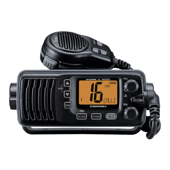
- Page 1 INSTRUCTION MANUAL VHF MARINE TRANSCEIVER iM200...
-
Page 2: In Case Of Emergency
Thank you for choosing this Icom product. CLEAN THE TRANSCEIVER THOROUGHLY WITH This product is designed and built with Icom’ s state of FRESH WATER after exposure to saltwater, and dry the art technology and craftsmanship. With proper care, it before operating. Otherwise, the transceiver's keys,... -
Page 3: Table Of Contents
PRECAUTIONS R WARNING! NEVER connect the transceiver to an AC outlet. BE CAREFUL! The transceiver and the hand microphone meet This may pose a fire hazard or result in an electric shock. IPX7 requirements for waterproof protection. However, once the transceiver or the microphone has been dropped, waterproof R WARNING! NEVER connect the transceiver to a power source protection cannot be guaranteed because of possible damage to... -
Page 4: Operating Rules
OPERATING RULES D PRIORITIES (2) OPERATOR’S LICENSE A Restricted Radiotelephone Operator Permit is • Read all rules and regulations pertaining to priorities the license most often held by small vessel radio and keep an up-to-date copy handy. A Distress call operators when a radio is not required for safety takes priority over all others. -
Page 5: Panel Description
PANEL DESCRIPTION ■ Front panel t CHANNEL KEY [CHAN] While pushing, push [16/C] to edit the channel name. (p. 7) Speaker Function display (p. 3) y SCAN KEY [SCAN]•[TAG] z Push to start or stop a scan. (p. 10) z Hold down for 1 second to set or clear the displayed channel as a TAG channel. -
Page 6: Panel Description
PANEL DESCRIPTION ■ Function display t CALL CHANNEL ICON Displayed when the Call channel is selected. (p. 4) y TAG CHANNEL ICON Displayed when a TAG channel is selected. (p. 10) u LOW POWER ICON Displayed when low power is selected. i DUPLEX ICON Displayed when a duplex channel is selected. -
Page 7: Basic Operation
BASIC OPERATION ■ Selecting a channel D Channel 16 D Call channel Channel 16 is a Distress and safety channel. It is used Each regular channel group has a separate Call to make an initial contact with a station or to make channel (Default: Channel 9*). - Page 8 The 4 digit channels are displayed as shown below. channels The channel number is displayed in the channel name The IC-M200 has 67 USA, 67 international, and 71 readout (at the bottom right) and the last 2 digits are Canadian preset channels.
-
Page 9: Receiving And Transmitting
BASIC OPERATION ■ Receiving and transmitting CAUTION: Transmitting without an antenna will TIP: To maximize the readability of your transmitted damage the transceiver. signal at a receiver station, pause a second after pushing [PTT], and then hold the microphone 5 to 10 cm from your mouth and speak at your normal 1. - Page 10 BASIC OPERATION ■ Setting a Call channel ■ Entering a channel name The Call channel is used to select Channel 9 (default). You can enter a channel name of up to 10 characters However, you can set another channel as the Call each.
- Page 11 BASIC OPERATION ■ The Microphone Lock function ■ The AquaQuake function The Microphone Lock function locks [▲], [▼], and You can use the AquaQuake function to clear water [HI/LO] on the supplied microphone. The function away from the speaker grill. The function helps drain prevents from accidentally changing channels or water away from the speaker housing by emitting a functions.
-
Page 12: Scan Operation
SCAN OPERATION ■ Scan types You can find ongoing calls by scanning the channels. PRIORITY SCAN CH 01 CH 02 NOTE: Before starting a scan • Set the channels you want to scan as TAG channels. CH 06 CH 16 CH 03 (p. -
Page 13: Setting Tag Channels
SCAN OPERATION ■ Setting TAG channels ■ Starting a scan For more efficient scanning, you can set the desired NOTE: Select the scan type from "Normal (default)" channel as a TAG channel or remove it from the or "Priority." (p. 13) TAG channels. -
Page 14: Dualwatch/Tri-Watch
DUALWATCH/TRI-WATCH Dualwatch and Tri-watch are convenient to monitor NOTE: Select Dualwatch or Tri-watch in the Set Channel 16 while you are operating on another mode. (p. 13) channel. 1. Select the desired channel. 2. Push [DW] to start Dualwatch or Tri-watch. DUALWATCH/TRI-WATCH SIMULATION •... -
Page 15: Set Mode
SET MODE ■ Set mode D Set mode sequence In the Set mode, you can change the settings of the transceiver’s functions. • Scan type • Scan resume timer NOTE: Available functions may differ depending on the dealer setting. Ask your dealer for details. D Set mode operation Starts with this item 1. -
Page 16: Scan Type
BASIC OPERATION ■ Set mode items D Dual/Tri-watch Select whether to start Dualwatch or Tri-watch after Push [▲] or [▼] to change the setting pushing [DW]. (p. 11) D Scan type Select whether to start the Normal scan or Priority scan after pushing [SCAN]. -
Page 17: Connections And Maintenance
CONNECTIONS AND MAINTENANCE ■ Connections w DC POWER CONNECTORS Connects the supplied DC power cable to an external 13.8 V DC power source. CAUTION: After connecting the DC power cable and external speaker lead, cover the connector and leads with a vulcanizing tape, as shown below, to prevent water seeping into the connector. -
Page 18: Supplied Accessories
CONNECTIONS AND MAINTENANCE ■ Supplied accessories ■ Replacing a fuse If a fuse blows, or the transceiver stops functioning, find and repair the cause of the problem. Then replace For the mounting bracket the damaged fuse with a new, adequately rated fuse. Mounting bracket Knobs Screws (5×20 mm) -
Page 19: Mounting The Transceiver
CONNECTIONS AND MAINTENANCE ■ Mounting the transceiver The universal mounting bracket supplied with your transceiver enables dashboard or overhead mounting. • Mount the transceiver fi rmly with the 2 supplied screws (5×20 mm) on only a fl at hard board that the knob screws won't penetrate. -
Page 20: Troubleshooting
TROUBLESHOOTING PROBLEM POSSIBLE CAUSE SOLUTION REF. Power does not come Power cable is improperly Reconnect the DC power cable p. 14 on when turning ON the connected. correctly. transceiver. No sound is heard from the Volume level is too low. Rotate [VOL] to a suitable listening p. -
Page 21: Channel List
CHANNEL LIST Channel number Frequency (MHz) Channel number Frequency (MHz) Channel number Frequency (MHz) Channel number Frequency (MHz) CAN Transmit Receive CAN Transmit Receive CAN Transmit Receive CAN Transmit Receive 156.050 160.650 157.050 161.650 156.425 156.425 157.375 161.975 156.050 156.050 21A 157.050 157.050 156.475 156.475 157.375 157.375... -
Page 22: Specifications And Options
• Maximum frequency deviation: ±5.0 kHz • Frequency tolerance: ±5.0 ppm Icom is not responsible for the destruction or damage to the Icom • Spurious emissions: Less than –70 dBc (High) transceiver, if the malfunction is because of: Less than –56 dBc (Low) •... -
Page 23: Index
Fuse, Replacing......... 15 Supplied accessories......15 High power .......... 6 Icom, Icom Inc. and Icom logo are registered trademarks of Icom Incorporated (Japan) in Japan, the United States, the United Kingdom, Germany, France, Spain, Russia, Australia, New Zealand, and/or other countries. - Page 24 A-7299H-1EX-q Printed in Japan 1-1-32 Kamiminami, Hirano-ku, Osaka 547-0003, Japan © 2016 Icom Inc.