Worcester 50/70 Installation And Servicing Instructions
Floor standing oil-fired pressure jet appliances
Hide thumbs
Also See for 50/70:
- User instructions & customer care manual (13 pages) ,
- Installation and servicing instrucnions (33 pages) ,
- Installation and servicing instructions (28 pages)
Table of Contents

Related Manuals for Worcester 50/70


Summary of Contents for Worcester 50/70
-
Page 1: Servicing Instructions
WORCESTER BOSCH 50/70, 70/90, 90/110 FLOOR STANDING OIL-FIRED PRESSURE JET APPLIANCES INSTALLATION AND SERVICING INSTRUCTIONS THESE INSTRUCTIONS ARE TO BE LEFT WITH THE APPLIANCE This appliance must be installed and serviced by a competent person... -
Page 2: Table Of Contents
1. Installation Regulations 2. General Information 1.1 General installation information and advice may be obtained 2.1 The Worcester Bosch range of appliances covered in these from the Oil Firing Technical Association for the Petroleum instructions have been designed to serve domestic central Industry (OFTEC). - Page 3 CONTROL THERMOSTAT DIFFERENTIAL 5°C HIGH LIMIT THERMOSTAT SET POINT 100°C +0/-6°C MANUAL RESET OVERHEAT THERMOSTAT 110°C +0/-6°C 50/70 Table 2. Electro Oil Inter B9B Burner (See Fig. 13) NOMINAL BOILER RATING AT NORMAL OPERATING TEMPERATURE Appliance Pump Fuel Flow Flue Gas Approx.
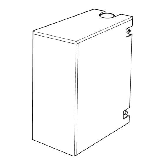
- Page 4 Fig. 2. General Assembly. Control Box Assembly Manual reset over- heat thermostat phial Split pin Phial retaining plug Control thermostat Automatic reset high phial limit thermostat phial Top panel Fire valve clip Manual reset overheat High limit thermostat thermostat Burner plug-in connector Strain relief bush...
-
Page 5: Siting The Appliance
High Level Low Level High Level Low Level 4.2 The appliance should be positioned on a non-combustible 50/70 209cm 314cm 105cm 209cm solid base as near to the flue location as possible. Care should be... - Page 6 taken beyond the eaves of the building. Where down-draught is Fig. 4. Flue Installation (Rear Discharge). experienced a suitable anti down-draught terminal should be fitted to the flue termination. Flue guard See Fig. 5 for The natural flue draught must be checked in the flue pipe flue terminating immediately above the appliance or in the hole provided in the positions.
-
Page 7: Oil Supply
Fig. 6. Oil Pump. 8. Oil Supply (a) Danfoss BFP 41. See Figs. 6 and 7. Cartridge filter 1 INLET 8.1 The oil storage tank must be installed in accordance with 2 RETURN BS 799 Part 5. The tank should be arranged with a slope of 1 in 24 away from the outlet valve with a sludge cock at its lower 3 BLEED AND PRESSURE GAUGE PORT... -
Page 8: Heating And Hot Water System
Fig. 7. Oil Supply. (a) Single pipe system Maximum oil level Isolating Wall valve Fire detection Oil tank Filter element Fire valve to BS 799 Part 2 Shut off valve Sludge cock Tank raised 1 in 24 Paper Burner (40 mm per metre) element oil filter Fire detection... - Page 9 Fig. 8. Typical Open Vent Gravity Primary System. Feed and Vent Cistern S.H. – Minimum static head 1m (3ft) measured from the top surface of the Primary cold Heating vent S.H. appliance or highest point in the feed (15mm min.) (22mm min.) heating system to the water level in the feed and expansion tank...
-
Page 10: Electrical
10.4 Programmer (See Fig. 11 and 12). 10. Electrical A time clock or programmer may be added to the control system. A two channel programmer will allow independent control of the central heating and hot water. However, it must be (See Figs. - Page 11 Fig. 11. Basic control. Room thermostat Time clock/ Circulating pump programmer 5 Amp Central Mains heating supply 230/ Hot water 240V 50Hz Control box Double outlet connector block frost thermostat Fig. 12. Off On No Demand. Circulating pump Cylinder Room thermostat thermostat Time clock/...
-
Page 12: Installation
5. The primary system should be flushed and treated in 11. Installation accordance with the recommendations of BS 7593: 1992. 11.5 Oil supply installation (See Fig. 7). 11.1 After unpackaging the appliance it is recommended that all Note: Never route the oil supply pipe/hose directly below the cabinet panels are removed, as described in Section 5, and combustion chamber base. -
Page 13: Commissioning The Appliance
runs in a steady state. This may take several attempts 12. Commissioning the Appliance depending on the oil pipe length and height. 12.10 Adjust the air shutter and pump pressure to the settings A qualified engineer must commission the appliance before recommended in Tables 2 to 4. - Page 14 Fig. 13. Electro Oil Inter B9 Burner. (50/70 Model). Locking screw Combustion Head Combustion head Spark gap 2 mm 2.0 - 2.5 mm Photocell 10 mm Adjusting disc Transformer Draught tube Nozzle Nozzle block Pressure adjustment screw Output Combustion Dimension Head PL 6/7/21.5/10 x 78 mm...
-
Page 15: Instructions To The User
13.2 Advise the user or purchaser of the precautions necessary Worcester Heat Systems Limited will be pleased to discuss and to prevent damage to the heating/hot water system and to the offer a comprehensive maintenance contract. -
Page 16: Routine Cleaning And Inspection
(c) Note the position of the air damper adjustment and check 14. Routine Cleaning And Inspection the air damper moves freely. (d) Check the air path to the burner head is clear. 14.1 The following should be carried out at least once per year (e) Clean both sides of the fan impeller and remove any debris for 28 second Kerosene and twice per year for 35 second Gas Oil, from the burner housing. -
Page 17: Short Parts List
2. Remove and clean the baffle retainer (70/90 and 90/110 element located within the appliance case. A fire valve clip is models only). See Fig. 16b. provided for this purpose as shown in Fig. 2. test the operation of the fire valve to ensure that the mechanism operates and that 3. -
Page 18: Fault Finding
LOCKOUT INDICATED BY RED LAMP ON CONTROL BOX To Re-set wait 2 minutes and press re-set button Ignition failure No oil delivery Air adjustment fault. Flame detection fault. Burner motor fails Intermittent Pulsation from nozzle. should be to operate. lockout. on start. - Page 19 NOTES:...
- Page 20 Worcester Heat Systems Limited, Cotswold Way, Warndon, Worcester WR4 9SW. Telephone: (01905) 754624. Fax: (01905) 754619. www.worcester-bosch.co.uk This booklet is accurate at the date of printing but will be superseded and should be disregarded if specifications and/or appearances are changed in the interests of continued improvement.