Table of Contents
Advertisement
Quick Links
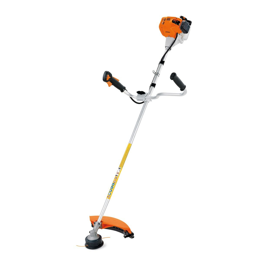
FS 75
Contents
1.
2.
2.1
2.2
2.3
2.4
2.5
Cutting attachment
2.6
2.6.1
2.6.2
2.7
3.
3.1
3.2
Assembly
4.
4.1
4.2
4.2.1
4.2.2
4.2.3
4.3
4.4
4.5
4.5.1
4.5.2
4.6
4.7
4.7.1
shaft
4.7.2
5.
5.1
5.2
5.2.1
5.2.2
5.3
2
6.
6.1
3
6.2
6.3
3
6.3.1
3
6.3.2
4
6.4
4
(ElastoStart)
5
6.5
6
6
6.6
6
7
7.
9
7.1
9
10
7.2
short-circuit wire
7.3
11
11
7.4
11
lever (throttle cable with
12
12
7.5
13
14
7.6
15
16
16
8.
16
18
8.1
18
8.2
8.2.1
18
8.2.2
8.2.3
23
8.2.4
23
8.3
24
8.4
24
8.5
25
26
27
9.
27
9.1
27
28
28
10.
28
10.1
29
10.2
10.3
30
30
10.4
31
11.
11.1
11.2
11.3
32
11.4
12.
Cutting device (HL 75)51
33
12.1
12.2
12.3
34
13.
34
13.1
35
13.2
35
35
35
36
38
39
39
40
© 1996, Andreas Stihl AG & Co., Waiblingen
41
41
43
43
43
45
46
47
47
47
48
50
51
51
53
55
55
57
1
Advertisement
Table of Contents

Related Manuals for Stihl FS 75


Summary of Contents for Stihl FS 75
-
Page 1: Table Of Contents
Adjustment (two adjusting screws) 37 Ignition system 8.2.4 Adjustment (one adjusting screw) Spark plug terminal Tank vent Ignition module Pickup body 5.2.1 Ignition timing Fuel tank/hoses 5.2.2 Removal and installa- tion Flywheel © 1996, Andreas Stihl AG & Co., Waiblingen... -
Page 2: Introduction
The tools can also series of power tools. be identified in the manual of Repairs to be undertaken on stan- "STIHL tools" on the basis of their dard parts and assemblies which part number. are used in several STIHL power... -
Page 3: Specifications
Specifications Engine STIHL single-cylinder two-stroke engine with special impregnated cylinder bore Displacement: 25.4 ccm Bore: 34 mm Piston stroke: 28 mm Power output to ISO 8893: 0.9 kW (1.2 HP) at 8000 rpm Max. permissible engine speed without cutting blades (cut-off speed): 10500 rpm (+ 000 rpm) Max. -
Page 4: Ignition System
M14 x 1.25 Length of thread: 9.5 mm Gearbox * Type: Helical-toothed bevel gears Gear ratio: 1.4 ** 1.24 *** Bearing: Deep groove ball bearing Lubrication: STIHL gear lubricant FS 75 only has a bearing housing FS 80, 85 FC 75... - Page 5 Cutting attachment * FS 75 FS 80 FS 85 FC 75 STIHL "Supercut 10-1" mowing head STIHL "Supercut 20-2" STIHL "Supercut 20-2" mowing head mowing head STIHL "Autocut 11-2" mowing head STIHL "Autocut 21-2" STIHL "Autocut 30-2" mowing head mowing head STIHL "Autocut 30-2"...
-
Page 6: Special Accessories
Special accessories 2.6.1 For the user Safety harness Safety goggles Bar scabbard for metal cutting tools STIHL multi-purpose grease (80 g tube) 0781 120 1109 STIHL gear lubricant (80 g tube) 0781 120 1117 2.6.2 For service Carburetor parts kit... -
Page 7: Tightening Torques
Tightening torques DG and P-type (Plastoform) screws are used in thermoplastic and alloyed materials. These screws cut a thread in the material when they are screwed in for the first time. The material is permanently deformed. The screws can be removed and refitted as often as desired. The strength of the screw connection is not impaired if the spe- cified tightening torque is maintained. - Page 8 This ensures that the screw engages the existing thread and does not cut a new thread, thus preserving the strength of the screw connection, 1) With washer 2) FS 75 3) FS 80, 85 4) FC 75 5) HL 75 Note: Screwdriver speed when working in plastic: Plastoform screws max.
-
Page 9: Clutch
Clutch Disassembly Refer to manual "Troubleshooting, standard repairs" for troubleshoo- ting procedures.. 100% • Remove screws. Important! The remaining wall thickness must be measured if the - Pull off fan housing with protec- inside diameter is distinctly worn. tive tube and set it aside. A new clutch drum must be fitted - see 11.4 - if the wall thickness has... - Page 10 Installation - Insert screws in fan housing and torque down to 5.5 Nm. - Remove locking strip from cylinder. - Screw in spark plug and torque down to 20 Nm. Important! Check that the separa- te connecting nut is securely loca- ted on the screw thread of spark •...
-
Page 11: Engine
Engine Muffler/spark arrester screen Leakage testing Defective oil seals and gaskets or cracks in castings cause leaks. Such faults allow supplementary air to enter the engine and thus impair the fuel-air mixture. This makes adjustment of the specified idle speed difficult, if not impossible. -
Page 12: Preparations
4.2.1 Preparations 4.2.2 Pressure test - Remove carburetor, see 8.2.2. - Remove outer screw on muffler. - Carry out preparatory steps, see 4.2.1. • Fit gasket in front of spacer - Back off inner screws half-way. • flange. Slide pressure hose of tester •... -
Page 13: Vacuum Test
4.2.3 Vacuum test Oil seals tend to fail when sub- Note: The oil seals are in good jected to a vacuum, i.e. the sealing condition if the indicated vacuum lip lifts away from the crankshaft is maintained or if the pressure during the piston’s induction stroke rises to no more than 0.3 bar because there is no internal coun-... -
Page 14: Oil Seals
Oil seals It is not necessary to disassemble the complete engine if only the oil seals have to be replaced. Clutch side: - Remove flywheel, see 5.3. - Lightly tap the oil seal with a suitable tube or punch to knock it out of its seat. -
Page 15: Exposing The Cylinder/ Spacer Flange
Exposing the cylinder/ spacer flange Always check and repair the fuel system, carburetor, air filter and ignition system before looking for faults on the engine. Refer to manual "Troubleshooting, standard repairs" for troubleshoo- ting procedures. - Remove fan housing with pro- tective tube, see 3.1. -
Page 16: Cylinder And Piston
Cylinder and piston 4.5.1 Removal 4.5.2 Installation • • - Preparations, see 4.4. Push piston pin (1) out of the Thoroughly clean sealing area piston with assembly drift (2) (1). • Unscrew cylinder base screws. 1114 893 4700. • Wet needle cage (2) with oil and Note: The two screws at the back Note: If the piston pin is stuck, it fit it in the small end. - Page 17 Note: Refer to manual "Trouble- shooting, standard repairs" for in- formation on using the assembly tool. • • Fit piston pin (1) on stub of as- Line up the piston rings so that sembly drift (2) and slide it into the radii at the ring gap meet at the piston (the pin slides home the fixing pin in the piston groove.
-
Page 18: Piston Rings
Piston rings Crankcase 4.7.1 Removing the crankshaft - Remove piston, see 4.5.1. Note: Coking residues must not be allowed to enter the crankcase when fitting the piston rings and/or cleaning the grooves. - Remove piston rings from piston. • Slide cylinder over piston; the - Remove cylinder, see 4.5.1 clamping strap slips downward... - Page 19 - Partly unscrew spindle of assem- bly tool ZS 5910 007 2220 (left- hand thread). • Hold assembly tool ZS against housing half on starter side so that the notch marked "1" is at the bottom. • • Remove piston, see 4.5.1.
-
Page 20: Installing The Crankshaft20
4.7.2 Installing the crankshaft Both halves of the crankcase can be replaced if the crankcase is da- maged. Each half of the crankcase is supp- lied with fitted deep groove ball bearing. If the original crankcase is used again, remove the gasket residues and clean the mating surfaces. - Page 21 Note: The bearing must be pres- sed in very quickly, as it imme- diately absorbs heat and begins to expand. • • Press deep groove ball bearing Insert the shorter stub of the into crankcase by hand as far as crankshaft into the deep groove possible.
- Page 22 • • • Hold spindle and turn sleeve Slide the clutch-side half of the Hold sleeve and turn spindle anticlockwise until it rests housing over crankshaft stub. clockwise until the two halves of against the deep groove ball the housing have come together. bearing.
-
Page 23: Ignition System
Ignition system Spark plug terminal Important! Great care must be taken when carrying out main- tenance and repair work or trou- bleshooting on the ignition system. The high voltages can cause serious or even fatal accidents! Troubleshooting on the ignition system should always start with the spark plug. -
Page 24: Ignition Module
Ignition module 5.2.1 Ignition timing The ignition timing is fixed and cannot be adjusted. Since there is no mechanical wear in these systems, the ignition timing cannot become maladju- sted. An internal fault in the circuit can, however, alter the switching point in such a way that a spark test will still show the system to be in order although timing is outside... -
Page 25: Removal And Installation
5.2.2 Removal and installation • - Remove fan housing with pro- Remove screws. - Position ignition module and tective tube, see 3.1. insert screws, but do not tighten them yet. • Disconnect short-circuit wire • from socket on ignition module. Secure ground wire (1) and connector tab (2) for short-circuit wire to upper screw. -
Page 26: Flywheel
Flywheel - Press ignition module against Unscrew the puller when the setting gauge and tighten screws flywheel has loosened. to a torque of 4.5 Nm. Remaining parts are installed in reverse order. Removing the flywheel: • Remove clutch, see 3.1. •... -
Page 27: Rewind Starter
All parts must be washed in paraf- fin or white spirit. The rewind spring and starter post must be lubricated with STIHL special lubricant, 13.2, before being installed. • Replace insert in starter cover if necessary. -
Page 28: Rewind Spring
- It should be lubricated with a few drops of STIHL special lubricant - see 13.2 - before being installed. • •... -
Page 29: Starter Rope
Starter rope (ElastoStart) - Hold starter grip firmly to keep - Remove starter cover, see 6.2. rope tensioned. - Remove starter rope from rope - Release rope rotor and let starter rotor, see manual "Troubleshoo- rope rewind slowly. ting, standard repairs". •... -
Page 30: (Elastostart)
Starter grip (ElastoStart) Starter carrier/pawl The starter grip is supplied with starter rope. - Remove starter cover, see 6.2. - Remove rope rotor, see manual "Troubleshooting, standard repairs". • Thread starter rope into hole in - Block piston with the aid of the side of rope rotor. -
Page 31: Throttle Control
Throttle control Throttle trigger / interlock lever Throttle cable with one short- circuit wire • • Slightly pull up interlock lever (1) Unhook throttle cable from and turn it aside until torsion throttle trigger. spring (2) is relaxed. The parts are assembled in rever- •... - Page 32 Throttle cable with one short-circuit wire • • - Remove shroud, see 3.1. Disconnect plug of short-circuit Ensure that throttle cable (1), wire from socket on ignition contact spring (2), protective • Remove screw (1). module. tube (3) and insulating element (4) are correctly seated.
-
Page 33: Throttle Cable With One
Contact spring/detent spring in control handle Throttle trigger / interlock lever Throttle cable with one short- Throttle cable with two short- circuit wire circuit wires - Refer to the manual "Trouble- shooting, standard repairs" with regard to changing the throttle trigger, interlock lever, contact spring and detent spring. -
Page 34: Throttle Cable With Two Short-Circuit Wires
Throttle cable with two short-circuit wires Adjusting the throttle cable Note: The throttle lever must butt against the stop on the carburetor body when the throttle trigger is in the full throttle position and against the idle speed adjusting screw when the trigger is in the idle position. -
Page 35: Fuel System
Fuel System Carburetor Air filter 8.2.1 Leakage testing Dirty and clogged air filters reduce - Wash foam filter in dry, non-flam- Refer to the manual "Trouble- engine power, increase fuel con- mable liquid (e.g. warm soapy shooting, standard repairs" for sumption and make starting more water) and dry it. -
Page 36: Removal And Installation
8.2.2 Removal and installation The carburetor is airtight if this value remains constant. If it drops, however, this may be due to two main reasons: 1. Inlet needle does not seal pro- perly (impurities in valve seat or sealing cone of inlet needle damaged or inlet control lever jammed). -
Page 37: Adjustment (Two Adjusting Screws)
8.2.3 Adjustment (two adjusting screws) The maximum speed of the carbu- Minor corrections may be neces- retors is mechanically limited by a sary at great altitudes (mountain cut-off valve. Unlike the case in regions), at sea level or when machines without cut-off valve, the changing the cutting attachment - maximum speed cannot be set to fitting a mowing head instead of... -
Page 38: Adjustment (One Adjusting Screw)
8.2.4 Adjustment (one adjusting screw) The carburetor does not have an Set idle speed adjusting screw for the maximum speed (H ). Engine stops when idling: The carburetor is tuned to ensure - Adjust to standard setting! that the engine is supplied with an optimum fuel/air mixture in all ope- LA = Turn idle speed adjusting rating conditions. -
Page 39: Tank Vent
Tank vent Pickup body Correct operation of the carburetor The diaphragm pump draws fuel is only possible if atmospheric out of the tank and into the carbu- pressure and internal fuel tank retor via the fuel hose. Any impuri- pressure are equal at all times. ties in the fuel are retained by the This is ensured by the tank vent. -
Page 40: Fuel Tank/Hoses
Fuel tank/ hoses - Drain fuel tank. - Remove starter cover, see 6.2. - Pull fuel hoses off elbow con- nectors on carburetor, see 8.2.2. Pickup body Fuel hoses • Draw pickup body out of fuel - Unscrew fuel filler plug and re- tank with assembly hook (1) move with chain. -
Page 41: Av System
AV system Repair The vibration damping connection between engine and protective tube is effected by a rubber buffer (AV system) in the fan housing. - Remove shroud, see 3.1. • • Release screws securing the Prise circlip out of fan housing. clamping collars of the control handle on machines with looped - Remove circlip above AV sleeve. - Page 42 • - Apply a few drops of lubricant - Pull rubber buffer off AV sleeve. Press rubber buffer into fan (e.g. washing-up liquid) between housing as far as possible so fan housing and rubber buffer. that the slit (1) is on the round side (2) of the housing.
-
Page 43: Shaft
Shaft 10.1 Cowhorn handle 10.2 Looped handle - Remove control handle, see 9.1. Looped handle without U-bar Looped handle with U-bar • • • Unscrew nuts (1). Unscrew nuts (1). Remove screws (1). • • • Remove lower clamping element Remove lower bracket (2). - Page 44 • • Looped handle with handle hose Line looped handle up at a Turn upper part of looped handle distance A = 15 cm in front of a little to the side and pull off • Remove screw (1). control handle and secure it in handle hose.
-
Page 45: Drive Shaft/Insulating Tube
Pull rigid drive shaft out of tube until it protrudes 20 mm protective tube. (FS 85) or 17 mm (FS 75, 80, FC 75) (value "A") at the end of the protective tube. If neces- sary, rotate the shaft slowly while... -
Page 46: Protective Tube
10.4 Protective tube - Remove drive shaft, see 10.3. - Remove cowhorn handle or looped handle, see 10.1 or 10.2. • - Pull out protective tube. Pully carrying ring apart and remove it. • On machines with looped hand- le, pull protective tube (1) out of The parts are installed in reverse control handle (2) at the same order. -
Page 47: Cutting Tool Drive
Cutting tool drive 11.1 Bearing housing (FS 75) 11.2 Gearbox (FS 80, 85) Refer to manual "Troubleshooting, standard repairs" for trouble- shooting procedures. • Deflector for mowing heads Undo clamping screws on gear- box. • Remove screws (1). - Pull gearbox off protective tube. -
Page 48: Gearbox (Fc 75)
11.3 Gearbox (FC 75) • • • Lock output shaft with pin, Unscrew clamping screw (1) and Unscrew bearing bolt. dia. 5 mm. knurled screw (2). - Remove wheel. • • Unscrew collar nut in the direc- Remove clamping element (3). tion of the arrow (left-hand thread). - Page 49 - Refer to manual "Troubleshoo- ting, standard repairs" for further details on disassembly and assembly. - Slide gearbox onto protective tube, turning the output shaft of the gear back and forth at the same time so that the square on the flexible input shaft can enga- ge the inner square of the drive pinion.
-
Page 50: Clutch Drum
11.4 Clutch drum • - Remove rubber buffer (AV sy- Press clutch drum in as far as stem) from fan housing, see 9.1. possible with assembly drift (1) 1108 893 4700. • Remove circlip for output stub of clutch drum with pliers (1) The remaining parts are installed 0816 610 1495. -
Page 51: Cutting Device
Cutting device (HL 75) 12.2 Cutting blade 12.1 Gearbox • • Undo clamping screws on Remove circlip with pliers (1) - Remove gearbox, see 12.1. straight gearbox. 0811 611 8200. • Remove screws. - Pull gearbox with cutting blade off protective tube. - Remove gearbox cover. - Page 52 • • • Remove gasket. Remove cutting device. Place guide (1) on workbench with screw heads (2) facing downwards. • Slip band spring (3) onto the screws with the pockets facing upwards. • Secure both blades (4) on the pockets with cutting edges wor- king against one another.
-
Page 53: Gearwheel
• tube scale. This forces approx. Remove gear wheel from gear 20 g of grease into the gearbox. housing. Note: Use STIHL multi-purpose grease - see 13.2 - to lubricate the gearbox. •... - Page 54 • Fit thrust plate with bent corners pointing towards gear housing. • Fit conrod with marking upwards. - Fit gear wheel with bevelled side of teeth pointing towards conrod.
-
Page 55: Special Service Tools And Aids
Special service tools and aids 13.1 Special tools Designation Part No. Remarks Locking strip for piston 0000 893 5903 Blocking crankshaft Press sleeve 4112 893 2401 Fitting oil seal (clutch side) Press sleeve 1115 893 4600 Fitting oil seal (starter side) Assembly sleeve 4112 893 2400 Protecting oil seal... - Page 56 Designation Part No. Remarks Assembly tool 4126 893 4900 Removing rubber buffer in AV sleeve Pliers A19 0816 610 1495 Removing external circlip from clutch drum Screwdriver QI-T27x150 5910 890 2400 For all socket head screws Press arbor 1108 893 4700 Removing and installing clutch drum Assembly stand...
-
Page 57: Servicing Aids
(370 g tube) Commercially available solvent- Cleaning crankshaft stub based degreasing agent without CFCs and halocarbons STIHL special lubricant 0781 417 1315 Bearing bore in rope rotor, rewind spring in rope rotor Ignition lead HTR (10 m) 0000 930 2251...