Table of Contents
Advertisement
Advertisement
Table of Contents
Troubleshooting

Related Manuals for Harman Kardon HK BDS 270


Summary of Contents for Harman Kardon HK BDS 270
-
Page 1: Service Manual
Service Manual HK BDS 270 2.1-channel 3-D Blu-ray home cinema receiver HK BDS 570 5.1-channel 3-D Blu-ray home cinema receiver CONTENTS OWNER’S MANUAL 2-34 EXPLODED VIEW AND PARTS, BDS 570 48 TROUBLESHOOTING GUIDE EXPLODED VIEW AND PARTS, BDS 270 50... - Page 2 harman/kardon BDS 270 + 570 Service Manual BDS 270/BDS 570 Blu-ray Disc receiver ™ Owner’s Manual Page 2 of 90...
-
Page 3: Table Of Contents
harman/kardon BDS 270 + 570 Service Manual BDS 270/BDS 570 Table of Contents IMportant Safety InStructIonS IntroDuctIon VerIfy LIne VoLtage Before uSIng unpackIng InStaLLatIon LocatIon cLeanIng MoVIng tHe receIVer SuppLIeD acceSSorIeS receIVer front-paneL controLS receIVer rear-paneL connectIonS reMote controL functIonS connectIonS preparIng tHe reMote controL SettIng up tHe receIVer... -
Page 4: Important Safety Instructions
15 of the fcc rules. operation cet appareil numérique de la classe B est conforme à la or repair, please contact your local Harman kardon service is subject to the following two conditions: (1) this device norme nMB-003 du canada. -
Page 5: Introduction
If any of these items are missing, please contact Harman kardon customer Service via www.harmankardon.com. -
Page 6: Receiver Front-Panel Controls
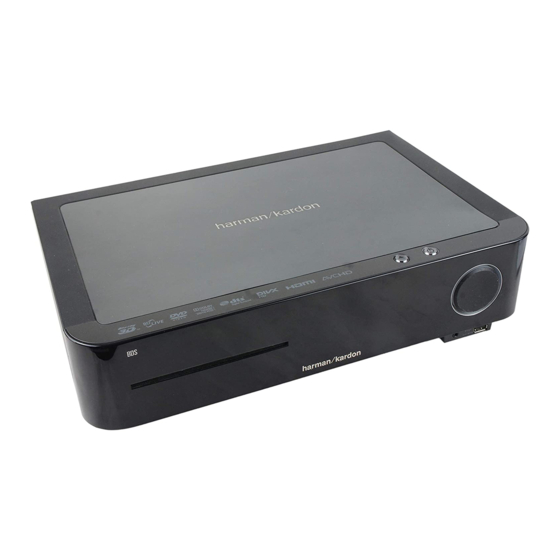
harman/kardon BDS 270 + 570 Service Manual BDS 270/BDS 570 Receiver Front-Panel Controls Receiver Front-Panel Controls Disc Slot Information Display eject Button Standby Button (on top panel) (on top panel) Headphone Jack uSB port Volume control Disc slot: Insert a compatible disc into the slot. the BDS receiver’s disc player will Headphone jack: Insert the 1/8-inch (3.5mm) stereo mini connector from a set accept 5-inch (12cm) and 3-inch (8cm) discs. -
Page 7: Receiver Rear-Panel Connections
harman/kardon BDS 270 + 570 Service Manual BDS 270/BDS 570 Receiver Rear-Panel Connections Receiver Rear-Panel Connections coaxial BD-Live Digital Input connector connector component HDMI Video Input Main Speaker HDMI Input Monitor out connector power Switch connectors Vents connectors connector ac power analog the Bridge IIIp optical... - Page 8 harman/kardon BDS 270 + 570 Service Manual BDS 270/BDS 570 Receiver Rear-Panel Connections The Bridge IIIP connector: connect the Bridge IIIp ipod/iphone dock (available note: See the Connections section, on page 10, for detailed information about making connections. separately) to this terminal. Main Power switch: this mechanical switch turns the BDS receiver’s power supply Analog Audio Output connector: connect this output to an analog recorder’s input on or off.
-
Page 9: Remote Control Functions
harman/kardon BDS 270 + 570 Service Manual BDS 270/BDS 570 Remote Control Functions Remote Control Functions Power button: pressing this button toggles the BDS receiver between the on and Standby modes. TV Power button: after you program the remote control, pressing this button turns power Button tV power Button the tV’s power on and off. - Page 10 harman/kardon BDS 270 + 570 Service Manual BDS 270/BDS 570 Remote Control Functions OK button: press this button to select the highlighted item on the on-screen menu. Program (Red) button: press this button to create a programmed playback list for the currently-playing disc.
-
Page 11: Connections
harman/kardon BDS 270 + 570 Service Manual BDS 270/BDS 570 Connections Connections Connecting the Receiver Terminals CAUTION: Before making any connections to the BDS receiver, ensure that the receiver’s AC cord is unplugged from the receiver and the AC outlet. Making speaker connections with the receiver plugged in and turned on could damage the speakers. - Page 12 harman/kardon BDS 270 + 570 Service Manual BDS 270/BDS 570 Connections Connecting a TV or Video Display Connecting Your Component Video Source Device If you have a video source device that has a component video connector (and does not use the supplied HDMI cable to connect the BDS receiver’s HDMI output to your tV/video have an HDMI connector), using the component video connector will provide superior display’s HDMI input.
- Page 13 harman/kardon BDS 270 + 570 Service Manual BDS 270/BDS 570 Connections Connecting Your Coaxial Digital Audio Source Device Connecting Your Analog Recorder If one of your non-HDMI source devices has a coaxial digital output, connect it to the connect an analog audio recorder’s inputs to the receiver’s analog audio output receiver’s coaxial Digital Input connector.
- Page 14 Ir receiver, such as the optional network wall jack that has Internet access. Harman kardon He 1000, to the receiver's remote Ir Input connector. note: the BDS receiver can not access content on other networked devices. the network connection enables only the receiver’s BD-Live features.
-
Page 15: Preparing The Remote Control
harman/kardon BDS 270 + 570 Service Manual BDS 270/BDS 570 Preparing the Remote Control Preparing the Remote Control 6. If you run out of codes for a component, you can search through all of the codes in the remote’s library for that component type. Installing the Batteries a) press and hold the aux button for three seconds. -
Page 16: Setting Up The Receiver
Please see the owners manual for additional explanation. 4:3 Pan & Scan 4:3 Letterbox Welcome to the Harman Kardon BDS Setup Wizard. Some simple information is needed to ensure you get the best experience from your product. You can adjust these settings later in addition top making changes to more advanced settings by selecting ‘Settings’... - Page 17 System Upgrade: Select this option when you want to install a firmware upgrade for your Select to adjust display settings BDS receiver that you’ve downloaded from a Harman kardon Web site or other Harman kardon source. TV: this option allows you to set the following display parameters: Setup Wizard: this option activates the receiver’s Setup Wizard (see Setup Wizard, on...
- Page 18 harman/kardon BDS 270 + 570 Service Manual BDS 270/BDS 570 Setting Up the Receiver Resolution: this option lets you select your tV’s highest resolution. “auto” automatically Dynamic Range Control: this setting makes the loud and quiet parts of a movie or music closer to the same volume (a process known as compression).
-
Page 19: Using The Receiver
harman/kardon BDS 270 + 570 Service Manual BDS 270/BDS 570 Setting Up the Receiver and Using the Receiver Setting the speaker distances: Information Menu 1. the front left and front right speakers will be highlighted. press the ok button. the Level and Distance selection screen will appear. - Page 20 harman/kardon BDS 270 + 570 Service Manual BDS 270/BDS 570 Using the Receiver to select a source from the list, use the cursor up/Down buttons to highlight the desired 5. Make sure that Level is highlighted, and press the ok button. the Volume adjustment source, then press the ok button to select it.
-
Page 21: Using The Disc Player
harman/kardon BDS 270 + 570 Service Manual BDS 270/BDS 570 Using the Receiver and Using the Disc Player Surround-Sound Modes Using the Disc Player your BDS receiver can decode and play audio programs in these native audio formats: Disc Handling Precautions •... - Page 22 harman/kardon BDS 270 + 570 Service Manual BDS 270/BDS 570 Using the Disc Player Supported Media Codecs Top Menu button: pressing this button displays the top menu for the Blu-ray Disc recording or DVD that is currently playing. note: this feature is disc-dependent. not all the BDS receiver can play media recorded in the following audio/video codecs: DVDs have top menus.
-
Page 23: Listening To Your Ipod/Iphone Device
harman/kardon BDS 270 + 570 Service Manual BDS 270/BDS 570 Using the Disc Player, Listening to Your iPod/iPhone Device and Using the Radio Playing Music CDs Receiver Information Display When the BDS receiver is playing a music cD, the top bar shows the current playback- When songs are playing, the display’s top line will scroll “artist <artist name>,”... -
Page 24: Listening To Audio Sources
harman/kardon BDS 270 + 570 Service Manual BDS 270/BDS 570 Using the Radio, Listening to Audio Sources and Playing Files from USB Devices and CD Data Discs Playing Files from USB Devices and CD Data Discs To listen to a preset station: press the channel + or channel –... -
Page 25: Playing Files From Usb Devices And Cd Data Discs
harman/kardon BDS 270 + 570 Service Manual BDS 270/BDS 570 Playing Files from USB Devices and CD Data Discs Viewing Photos Thumbnail (Yellow) button: pressing this button while playing a slide show displays thumbnail images of all photos in the slide show. use the cursor and ok buttons to In the top directory, select “photo.”... -
Page 26: Using Playlists
harman/kardon BDS 270 + 570 Service Manual BDS 270/BDS 570 Playing Files from USB Devices and CD Data Discs, and Using Playlists If a selected Mp3 file has an album cover-art ID3 tag, the art will be displayed on the Options button: pressing this button displays any available options for the song screen. -
Page 27: Troubleshooting
Troubleshooting Troubleshooting If your BDS receiver isn’t performing the way you think it should, check to see if the problem is covered in this section before calling your dealer or contacting a Harman kardon representative. Problem Solution the receiver won’t power up (the power indicator is not lit): •... -
Page 28: Aux Component Remote-Control Code List
0121 0087 0029 BrockSonIc 0206 0205 grunDIg 0193 BuSH 1010 1020 1040 1043 1092 HaLL Mark 0128 BuSH (uk) 1044 Harman kardon 0201 century 1023 1088 HItacHI 0147 0144 0132 0128 0123 cItIZen 0132 0128 0123 0045 Hytek 0016 coMteL... - Page 29 harman/kardon BDS 270 + 570 Service Manual BDS 270/BDS 570 Aux Component Remote-Control Code List TV/DVR Manufacturer Code Numbers Manufacturer Code Numbers Lg (goLDStar) 0132 0128 0122 0110 0101 0002 SaMSung 0145 0132 0128 0124 0022 0020 0013 2004 2003 LLoytron 0173 0172...
- Page 30 harman/kardon BDS 270 + 570 Service Manual BDS 270/BDS 570 Aux Component Remote-Control Code List Cable Tuners Manufacturer Code Numbers Manufacturer Code Numbers 3011 3001 3220 3197 aLLegro 3111 pace 3179 aMerIcaSt 3212 panaSonIc 3214 3189 3177 3176 3053 arcHer 3112 pantHer 3114...
- Page 31 harman/kardon BDS 270 + 570 Service Manual BDS 270/BDS 570 Aux Component Remote-Control Code List Satellite Tuners Manufacturer Code Numbers Manufacturer Code Numbers aIWa 6041 HItacHI 5055 5004 6006 6011 akaI 6033 HouSton 5063 tracker aLBa 6001 6011 HugHeS 5089 5037 5005 5006...
- Page 32 harman/kardon BDS 270 + 570 Service Manual BDS 270/BDS 570 Aux Component Remote-Control Code List Satellite Tuners Manufacturer Code Numbers Manufacturer Code Numbers panaSonIc 5069 5066 5057 5053 6024 6031 6006 panSat 5020 Sky MaSter 6033 perSonaL 5018 SkyLaB 6021 caBLe Sony 5005...
-
Page 33: Specifications
harman/kardon BDS 270 + 570 Service Manual BDS 270/BDS 570 Specifications Specifications BDS 570 Receiver BDS 270 Receiver Audio Section continuous average power, stereo model: 65 watts per channel, 20Hz – 20kHz, @ <0.1% tHD, both channels driven into 6 ohms Multichannel power (BDS 570 only): 65 watts per channel, 20Hz –... - Page 34 © 2011 HarMan International Industries, Incorporated. all rights reserved. Harman kardon is a trademark of HarMan International Industries, Incorporated, registered in the united States and/or other countries. ezSet/eQ is a trademark of HarMan International Industries, Incorporated. Blu-ray Disc and BD-Live are trademarks of the Blu-ray Disc association.
-
Page 35: Software Upgrade
harman/kardon BDS 270 + 570 Service Manual Software upgrade Preparation to upgrade software 1) Power on and press "SETTINGS" button and ‘Left’ button on the remote control to check the SW version info . 2) Select and match upgrade package by the SW version info, for example , BDS270_EU VX.XX.XX, you must select the package HK_BDS270_EU_VX.XX.XX 3) Unzip the package, copy the ‘UPG’... - Page 36 harman/kardon BDS 270 + 570 Service Manual Trouble shooting Chart Power on led doesn't work power on led doesn't work Switch performance check change switch Check the c able XS603 is Reconnect the cable connect well to po wer board CN501 Check+5V,+12V,+5VSTB voltage on the power and...
- Page 37 harman/kardon BDS 270 + 570 Service Manual Trouble shooting Chart No display on VFD No display on VFD Check every supply Refer to Power supply board part voltage on AM board is normal Check+5V,+12V,+5VSTB Fix the connection XS603 on front board voltage on the power and and CN501 on power board, and 20pin front board...
- Page 38 harman/kardon BDS 270 + 570 Service Manual Trouble shooting Chart Remote control does not work Remote control does not work Check whether the remote Replace the battery for remote controller’s battery controller exhausted or not. Check the 2pi n FFC cable from AM to BD board is Reconnect the cable connect wenll...
- Page 39 harman/kardon BDS 270 + 570 Service Manual Trouble shooting Chart Can’t read disc or can’t eject Can’t read disc or can’t eject Check whether Check the co nnection 4pin cable from the DVD loader running is BD board normal Check 45pin 5pin cable...
- Page 40 harman/kardon BDS 270 + 570 Service Manual Trouble shooting Chart 5.1/2.1 channel no audio output 5.1/2.1 channel no audio output Check the 10pin/4pin cable is Reconnect well connect well from AM to JC board Check XP701 is short Replace the AM board to GND Check +32V at XP702 on Refer to Power supply board...
- Page 41 harman/kardon BDS 270 + 570 Service Manual Trouble shooting Chart BD/DVD/CD no audio output BD/DVD/CD audio output Check HDMI audio is ok Check the sof tware setup HDMI audio output is ON or OFF Turn to ON Check the 22pin cable from BD to AM board is Reconnect well connect well...
- Page 42 harman/kardon BDS 270 + 570 Service Manual Trouble shooting Chart Tuner FM does not work Tuner FM does not work Check the DVD mode is Replace the AM board OK,audio output is ok Check Tuner module Check AM boa rd tuner volt age supply pin5 supply voltage is circuit.
- Page 43 harman/kardon BDS 270 + 570 Service Manual Trouble shooting Chart AUX in does not work AUX in does not work Check the D VD mode is Replace the AM board OK,audio output is ok Check the AM board U 18 Check main board...
- Page 44 harman/kardon BDS 270 + 570 Service Manual Trouble shooting Chart IPOD in does not work IPOD in does not work Check the D VD mode is Replace the AM board OK,audio output is ok Check whether bad so lder Correct connection exists on pins of BRIDGE Ⅲ...
- Page 45 harman/kardon BDS 270 + 570 Service Manual Trouble shooting Chart COAX/OPTICAL does not work COAX/OPTICAL does not work Check the D VD mode is Replace the AM board OK,audio output is ok Check coax/optical Replace the RCA connector RCA connector is ok Check U714 Check...
- Page 46 harman/kardon BDS 270 + 570 Service Manual Trouble shooting Chart Fan can not rotate FAN can not rotate Check the F AN Check the voltage power supply circuit of FAN Replace a new fan Ihdmi input does not output HDMI input does not output check connector is HDMI IN OUT Correct connection...
- Page 47 harman/kardon BDS 270 + 570 Service Manual Trouble shooting Chart Line out does not output Line out does not output Check the D VD mode is Replace the AM board OK,audio output is ok check BDSX70 is working Replace P4 RCA Page 47 of 90...
- Page 48 harman/kardon BDS 270 + 570 Service Manual Page 48 of 90...
- Page 49 harman/kardon BDS 270 + 570 Service Manual BDS570EU Spare parts list Spec Description Part Number BDS270 Spare parts (the Location refer to exploded view) ASSY-MAIN BOARD 08-BDS570-MA0 ASSY-POWER BOARD 08-BDS570-PW0 ASSY-AMPLIFIER BOARD 08-BDS570-AM0 ASSY-LOADER 08-LV0300-BD310 ASSY-LOADER CONNECTION 08-VSHM93-IN0 BOARD ASSY1 ASSY-FRONT PANEL ASSEMBLY 08-BDS7F1-001 KONB ASSEMBLY...
- Page 50 harman/kardon BDS 270 + 570 Service Manual Page 50 of 90...
- Page 51 harman/kardon BDS 270 + 570 Service Manual Exploded view for BDS270: This is general mechanical exploded view for BDS270. Please refer to the model set for detail information. ASSY1 includes components:18,19,20,21,22,23,24,25,26,33,34,35,36 Page 51 of 90...
- Page 52 harman/kardon BDS 270 + 570 Service Manual BDS270 SERVICE PARTS Location No. TCL P/N Description ASSY-MAIN BOARD 08-BDS570-MA0 ASSY-AMPLIFIER BOARD 08-BDS270-AM0 HDMI HDMI GOLD CABLE,1.5M 46-HDI015-19G FM CABLE 47-ANT022-XX0 51-DC0180-0KEM9-M EUROPEAN POWER CORD 1.8m FOOT A 56-BDS8E1-0HA FOOT B 56-BDS8E2-0HA RUBBER PAD 59-993700-000 REAR PANEL...
- Page 53 harman/kardon BDS 270 + 570 Service Manual Spec Description Part Number BDS270 Spare parts (Location refers to exploded view) 08-BDS570-MA0 ASSY-MAIN BOARD D303 09-LL4148-ATX SMD. SWITCHING DIODE LL4148 LL-34 Q1,Q2,Q206,Q2 13,Q215,Q217, NPN TRANSISTOR 3DG3904M SOT-23 Q5,Q6,Q800,Q8 02,Q803 12-BT3904-0BX Q804,Q805,Q80 PNP TRANSISTOR 2SB1132 SOT89 12-SB1132-QBX Q207 12-SM3403-0BX...
- Page 54 harman/kardon BDS 270 + 570 Service Manual U714 13-CS8422-00B DIGITAL ICCS8422 IC CW1117 13-CW1117-18B U712,U713 13-DRV602-00B LINE DRIVER DRV602 U732 IC EUP3482 13-EUP348-2DB U729 MCU PIC24FJ256GA108 TQFP80 13-P24FJ2-56B 13-S1206S-00B IC S-1206B33-M3T1G SOT-23-3 U731 TAS5352 125 W STEREO DIGITAL AMPLIF 13-TAS535-20B U711 8-CHANNEL DIGITAL AUDIO PWM 13-TAS550-80B...
- Page 55 harman/kardon BDS 270 + 570 Service Manual D609 10-1N4148-ABX DIODE 1N4148 DO-35 ZD602 10-79C39V-DBX ZENER DIODE BZX79C39V ZD603,ZD604 10-HS3V3A-DBX DIODE ZENER 3.3HSA 3.3V ±5% DO-35 Q609,Q610,Q61 4,Q615,Q619,Q NPN TRANSISTOR MMBT8050C SOT-23 620,Q621 12-BT8050-CBX Q611,Q612 12-BT8550-CBX PNP TRANSISTOR MMBT8550C SOT-23 Q601,Q602,Q60 N-channel MOSFET 2SK3018 SOT-323 12-SK3018-0BX U602...
- Page 56 harman/kardon BDS 270 + 570 Service Manual U501 13-TNY180-PNB POWER CONTROL INTEGRATE CITCUIT TR501 22-NTC030-MX0-M THERMISTOR NTC030 CE501,CE502 25-GNF101-M1X CAP. ELEC 100uF ±20% 450V 105℃ C538 26-AKA100-JZX-M CERAMIC CAPACITOR 10PF ±5% 1KV C521 26-AKA102-KBX-M CERAMIC CAPACITOR 1000PF ±10% 1KV C505 26-AKA222-KBX-M CERAMIC CAPACITOR 2200pF ±10% 1KV 26-AKK101-KBX-M...
- Page 57 harman/kardon BDS 270 + 570 Service Manual 7-26 7-26 Front Control Board Print-layout(top side): Page 57 of 90...
- Page 58 harman/kardon BDS 270 + 570 Service Manual 7-27 7-27 Front Control Board Print-layout(bottom side): Page 58 of 90...
- Page 59 harman/kardon BDS 270 + 570 Service Manual 7-28 7-28 Amplifier Control Board Print-layout(top side): Page 59 of 90...
- Page 60 harman/kardon BDS 270 + 570 Service Manual 7-29 7-29 Front Control Board Print-layout(bottom side): Page 60 of 90...
- Page 61 harman/kardon BDS 270 + 570 Service Manual 7-30 7-30 Power Supply Print-layout(top side): Page 61 of 90...
- Page 62 harman/kardon BDS 270 + 570 Service Manual 7-31 7-31 Power Supply Print-layout(bottom side): Page 62 of 90...
- Page 63 harman/kardon BDS 270 + 570 Service Manual 7-32 7-32 Main Board Print-layout(top side): Page 63 of 90...
- Page 64 harman/kardon BDS 270 + 570 Service Manual 7-33 7-33 Main Board Print-layout(bottom side): Page 64 of 90...
-
Page 65: Wiring Diagram
harman/kardon BDS 270 + 570 Service Manual WIRING DIAGRAM OUTPUT BOARD 10P/2.0MM BRIGHE III LIN1 LIN2 OPTI OPTI IR_IN 47-BRI001-XX0 CAL1 CAL2 RIN1 RIN2 TUNER IPOD_LROUT COAX LOUT ROUT TRIGGER 6P/2.0MM TL072C 07-KSTS78-00S 13-TL072B-00B MIC_IN TL072C 10P/2.0MM 13-TL072B-00B SPDIF IPOD_IN MIC_IN 13-TPA611-2A2 AKM5367... - Page 66 harman/kardon BDS 270 + 570 Service Manual Front Control Board Circuit Diagram: VFD SCH VC3.3V R657 R657 R684 R684 TO POWER BOARD XP807 XP807 TP61 TP61 VR601 VR601 TP62 TP62 VOL_+ R679 R679 TP63 TP63 VOL_+ VOL+ TP64 TP64 VOL_- R661 R661 TP66...
- Page 67 harman/kardon BDS 270 + 570 Service Manual FB15 FB15 Front Control Board Circuit Diagram: VOL FB500/0.5A FB500/0.5A R614 27K R614 27K +12V_MIC REFM R695 R695 R606 R606 HP_ROUT CE603 CE603 C611 C611 R615 R615 CE604 CE604 C606 C606 CE602 CE602 470uF/16V 470uF/16V 47uF/16V...
- Page 68 harman/kardon BDS 270 + 570 Service Manual Inter.Control Board Circuit Diagram: 4PIN/1.0mm 4PIN/1.0mm sled motor connector 4PIN/1.0mm 4PIN/1.0mm COMMON 8pin/1.0mm 8pin/1.0mm COMMON Page 68 of 90...
- Page 69 harman/kardon BDS 270 + 570 Service Manual BDS270 JACK Output Board Circuit Diagram: Linewidth 2mm XP711 XP711 L/R SPK JACK L/R SPK JACK P750 P750 3.96 PIN 3.96 PIN Page 69 of 90...
- Page 70 harman/kardon BDS 270 + 570 Service Manual Power Supply Board Circuit Diagram: C521 C521 1000pF/1KV 1000pF/1KV R540 R540 D507 D507 SR3100/3A/100V SR3100/3A/100V Q505 Q505 P_AP6679GI P_AP6679GI +12V D501 D501 1N5407/3A/800V 1N5407/3A/800V CY503 CY503 470pF/250VAC 470pF/250VAC ZD505 ZD505 Q508 Q508 R542 R542 FB501 FB501...
- Page 71 harman/kardon BDS 270 + 570 Service Manual Main Board Circuit Diagram:POWER +12V 135MA 5V_STB R296 R296 1.1V GND1 GND1 5V_STB 5V_STB 1.1V NC/20K NC/20K POWER +12V +12V TM64 TM64 behind of Caps 1.1V R295 R295 NC/100K NC/100K 0.1uF/25V/Y5V 0.1uF/25V/Y5V 2D BD R294 R294 Close to DC-DC...
- Page 72 harman/kardon BDS 270 + 570 Service Manual Main Board Circuit Diagram:MT8555.DDR Part1 1.2V U101 U101 U102 U102 R101 R101 AVDD12_MEMPLL 1.5V A_DQ3 A_RA0 A_DQ18 A_RA0_2R C101 C101 C102 C102 AA25 A_DQ7 A_RA1 A_DQ23 A_RA1_2R DVCC18_IO_1 AE10 A_DQ1 A_RA2 A_DQ19 A_RA2_2R DVCC18_IO_1 0.1uF/16V/Y5V 0.1uF/16V/Y5V...
- Page 73 harman/kardon BDS 270 + 570 Service Manual Main Board Circuit Diagram:MT8555.DDR Part2 1.1V 1.1V B_DQ0 DVCC10_K RDQ0_B B_DQ1 U201 U201 U202 U202 DVCC10_K RDQ1_B B_DQ2 DVCC10_K RDQ2_B B_DQ3 B_DQ1 B_RA0 B_DQ19 B_RA0_2R DVCC10_K RDQ3_B C201 C201 C202 C202 C212 C212 C203 C203 C204...
- Page 74 harman/kardon BDS 270 + 570 Service Manual Main Board Circuit Diagram:HDMI_OUTPUT AVDD33_VDAC_R AVDD33_VDAC_R AOMCLK AVSS33_VDAC_R AOBCK AOLRCK AOLRCK 3.3V AVDD33_VDAC_X AOSDATA0 AVDD33_VDAC_X AOSDATA0 AOSDATA1 AVSS33_VDAC_X AOSDATA1 AOSDATA2 AOSDATA2 AVDD33_VDAC_R AVDD33_VDAC_BG AVDD33_VDAC_BG AOSDATA3 AVSS33_VDAC_BG AOSDATA4 C302 C302 AVDD33_XTAL AVDD33_XTAL 0.1uF/16V/X7R 0.1uF/16V/X7R AVSS33_XTAL SPDIF 3.3V...
- Page 75 harman/kardon BDS 270 + 570 Service Manual 7-10 7-10 Main Board Circuit Diagram:MT8555.FLASH NAND Flash 3.3V 3.3V 3.3V 3.3V U401 U401 DVCC33_IO_5 STXN DVCC33_IO_5 STXP R402 R402 DVCC33_IO_2 DVCC33_IO_2 SRXP DVCC33_IO_3 SRXN C400 C400 C401 C401 DVCC33_IO_3 R406 R406 0.1uF/16V/X7R 0.1uF/16V/X7R 4.7uF/10V/Y5V 4.7uF/10V/Y5V...
- Page 76 harman/kardon BDS 270 + 570 Service Manual 7-11 7-11 Main Board Circuit Diagram:MT8555_VFD/IR 3.3V_STBY DVCC33_IO_STB DVCC33_IO_STB GPIO8 24PIN/0.5mm 24PIN/0.5mm DVCC33_IO_STB ETCOL ETCRS ETMDC INT_7181 ETMDIO_AO2MCK ETMDIO OPEN ETRXCLK TM42 TM42 3.3V_STBY MCLK_OUT TM45 TM45 3.3V_STBY ETRXD0 HMCLK 22*4 22*4 SCLK_OUT TM44 TM44 ETRXD1...
- Page 77 harman/kardon BDS 270 + 570 Service Manual 7-12 7-12 Main Board Circuit Diagram:Audio_DAC 1.2V R651 R651 AVDD12_HDMI_RX VDINHS RN126 RN126 VDD12_HDMI_RX VDINHSYNC VDINVS VDD12_HDMI_RX VDINVSYNC 22*4 22*4 VDINCLK VDINCLK C652 C652 VDINDE C653 C653 VDINDE 5 RN125 RN125 VDINVS 0.1uF/16V/X7R 0.1uF/16V/X7R 22*4 22*4...
- Page 78 harman/kardon BDS 270 + 570 Service Manual 7-13 7-13 Main Board Circuit Diagram:Video/SD_Output Differential Signal ! V3.3V No Through Hole ! HDMI TX 100 ohm - Impedance HDMI Port V3.3V V7622 D314 D314 NC/1N4007/1A/1000V NC/1N4007/1A/1000V NC/1N4007/1A/1000V NC/1N4007/1A/1000V ACM2012H-900-2P ACM2012H-900-2P PESD_TPD4S010B PESD_TPD4S010B TX2+ F_TX2+...
- Page 79 harman/kardon BDS 270 + 570 Service Manual 7-14 7-14 Main Board Circuit Diagram:MT8555_FE FE RS232 Port 3.3V NC1206/SMD NC1206/SMD A1.2V TRINA TRINA TRINA TRINB TRINB TRINB FE_GND 0603-R 0603-R URXD C227 C227 TRINC TRINC TRINC UTXD TRIND NC1206/SMD NC1206/SMD FE_GND C223 C223 0.1uF/25V/Y5V...
- Page 80 harman/kardon BDS 270 + 570 Service Manual 7-15 7-15 Main Board Circuit Diagram:MOTOR_Driver M12V_T V14REF_R 90MA GAINSW3 GAINSW3 C262 C262 4.7uF/10V/Y5V 4.7uF/10V/Y5V VCC_D C263 C263 0.1uF/25V/Y5V 0.1uF/25V/Y5V C19V SLED2_N FB15 FB15 10/2A 10/2A C265 C265 FOC1- MVCC_R SLED2_P FOC1- 0.1uF/25V/Y5V 0.1uF/25V/Y5V FOC1+ P12V_3...
- Page 81 harman/kardon BDS 270 + 570 Service Manual 7-16 7-16 Amplifier Board Circuit Diagram:AMP+DSP +3.3V TAS5352DDV6EVM +3.3V R732 R732 R701 R701 R703 R703 R704 R704 R705 R705 RN704 RN704 47*4 47*4 /HP_SELO CE717 CE717 C710 C710 /BKND_ERR BKND_ERR /BKND_ERR 47uF/16V 47uF/16V 0.1uF/50V/Y5V 0.1uF/50V/Y5V PWM5...
- Page 82 harman/kardon BDS 270 + 570 Service Manual 7-17 7-17 Amplifier Board Circuit Diagram:L+SL OUT XP701 XP701 10PIN/3.96mm 10PIN/3.96mm TP116 TP116 C776 C776 TP117 TP117 TP118 TP118 0.1uF/50V/X7R 0.1uF/50V/X7R TP119 TP119 TP122 TP122 TP123 TP123 R746 R746 TP124 TP124 D711 D711 TP125 TP125 TP126...
- Page 83 harman/kardon BDS 270 + 570 Service Manual 7-18 7-18 Amplifier Board Circuit Diagram:R+SR OUT C737 C737 0.1uF/50V/X7R 0.1uF/50V/X7R FB80@100MHz FB80@100MHz R750 R750 C1003 C1003 CE747 CE747 FAN_CT# 0.1uF/50V/Y5V 0.1uF/50V/Y5V D705 D705 C738 C738 1000uF/50V 1000uF/50V 0.1uF/50V/X7R 0.1uF/50V/X7R CE730 CE730 C792 C792 R785 R785...
- Page 84 harman/kardon BDS 270 + 570 Service Manual 7-19 7-19 Amplifier Board Circuit Diagram:C OUT PVDD TP34 TP34 C756 C756 C799 C799 0.1uF/50V/Y5V 0.1uF/50V/Y5V 0.01uF/50V/Y5V 0.01uF/50V/Y5V R763 R763 R760 R760 XP702 XP702 6PIN/2.5mm 6PIN/2.5mm LAYOUT NOTE: LAYOUT NOTE: LAYOUT NOTE: EMI SNUBBER EMI SNUBBER EMI SNUBBER PLACE TO THE...
- Page 85 harman/kardon BDS 270 + 570 Service Manual 7-20 7-20 Amplifier Board Circuit Diagram:Main Power CE39 CE39 SD+3.3V 70/1A 70/1A 470uF/16V 470uF/16V +12VIN 70/1A 70/1A PNP_3CA8550C PNP_3CA8550C VCC_FAN 0.1uF/25V/Y5V 0.1uF/25V/Y5V CS3.3V 1.1A +3.3V 70/1A 70/1A C101 C101 CE24 CE24 U733 U733 AT1529 AT1529 CE65...
- Page 86 harman/kardon BDS 270 + 570 Service Manual 7-21 7-21 Amplifier Board Circuit Diagram:AK5367 33pF/50V/NP0 33pF/50V/NP0 33pF/50V/NP0 33pF/50V/NP0 C122 C122 C153 C153 1.74K/0.1% 1.74K/0.1% 49.9k/0.1% 49.9k/0.1% 0.1uF/25V/Y5V 0.1uF/25V/Y5V 39pF/50V/NP0 39pF/50V/NP0 IPOD_LOUT A-12V A-12V R175 R175 /RST TUNER_reset R176 R176 TL072 TL072 49.9k/1% 49.9k/1% TUNER_SEN...
- Page 87 harman/kardon BDS 270 + 570 Service Manual 7-22 7-22 Amplifier Board Circuit Diagram:74LVC541 +3.3V +3.3V_LINEOUT 70/1A 70/1A C755 C755 C149 C149 1uF/16V/Y5V 1uF/16V/Y5V R834 R834 0.1uF/25V/Y5V 0.1uF/25V/Y5V 100K 100K R843 R843 R847 R847 2.2K 2.2K 2.2K 2.2K LINE_MUTE R841 R841 C793 C793 100K...
- Page 88 harman/kardon BDS 270 + 570 Service Manual 7-23 7-23 Amplifier Board Circuit Diagram:DSP CS3.3V ONLY 1 SPI FLASH POPULATED BOTH FOOTPRINTS REPRESENTED R144 R144 2.7K 2.7K 2.7K 2.7K SD_A12 is used only on FLASH 2.7K 2.7K CSD+3.3V SPI_FLASH_CS IC_128P_CS495314 IC_128P_CS495314 so route length is not critical SCLK_CS SCPI_CLK...
- Page 89 harman/kardon BDS 270 + 570 Service Manual 7-24 7-24 Amplifier Board Circuit Diagram:SPDIF 0.01uF/50V/X7R 0.01uF/50V/X7R C1082 C1082 C1083 C1083 C1084 C1084 TP114 TP114 1.8uH/25mA 1.8uH/25mA R35 0 R35 0 SD+3.3V RN124 RN124 TP90 TP90 C779 C779 56*4 56*4 1uF/16V/Y5V 1uF/16V/Y5V TP103 TP103 AD_LRCK...
- Page 90 harman/kardon BDS 270 + 570 Service Manual 7-25 7-25 Amplifier Board Circuit Diagram:MCU +3.3V_STB 3.3V_MCU 400/200mA 400/200mA C1078 C1078 C104 C104 BD MUTE 2.2uF 2.2uF 0.1uF/25V/Y5V 0.1uF/25V/Y5V CE20 CE20 L BD MUTE 3.3V_MCU R236 R236 R223 R223 HP_DET HP_SELO R231 R231 0.1uF/25V/Y5V 0.1uF/25V/Y5V...