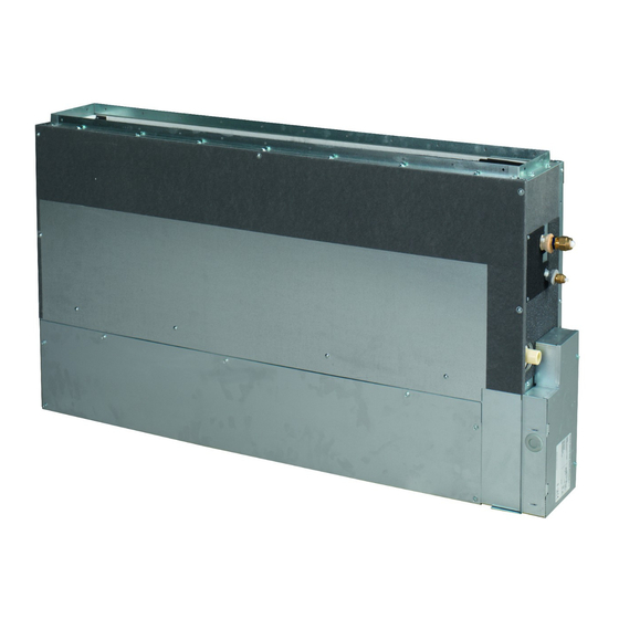
Summary of Contents for Daikin VRV SYSTEM FXNQ20A2VEB
-
Page 1: Installation Manual
INSTALLATION MANUAL System Inverter Air Conditioners FXNQ20A2VEB FXNQ25A2VEB FXNQ32A2VEB FXNQ40A2VEB FXNQ50A2VEB FXNQ63A2VEB... - Page 2 3P323721-8J...
-
Page 3: Table Of Contents
VRV SYSTEM Inverter Air Conditioners Installation manual A foundation of insufficient strength may result in the equip- CONTENTS ment falling and causing injury. 1. SAFETY PRECAUTIONS..........1 • Carry out the specified installation work after taking into 2. BEFORE INSTALLATION..........2 account strong winds, typhoons or earthquakes. -
Page 4: Before Installation
• Do not install the air conditioner in the following locations: 2-2 ACCESSORIES Where there is a high concentration of mineral oil spray Check the following accessories are included with your unit. or vapour (e.g. a kitchen). Metal Drain Insulation Plastic parts will deteriorate, parts may fall off and water Sealing pad Name... -
Page 5: Selecting Installation Site
(2) Use suspension bolts for installation. Check whether Is something blocking the air It may result in insufficient the wall/floor is strong enough to support the weight of outlet or inlet of either the cooling. the unit or not. If there is a risk, reinforce the wall/floor indoor or outdoor units? before installing the unit. -
Page 6: Indoor Unit Installation
■ Removing the legs If it is necessary to remove the legs, follow these instructions: [ How to secure washers ] [ Securing the hanger bracket ] • In case of bottom suction (1) Remove the air filter Washer for Insert below (2) Unscrew 4 screws which hold both legs on the bottom hanging bracket... -
Page 7: Outdoor Unit Installation
NOTE: The unit must be installed within a fully enclosed 3) Floor standing concealed installation casing built by others. The casing shall include as minimum Install the unit according to the figures below. a removable access panel, suction air grille and discharge Unit of measurement = mm air grille. - Page 8 • For the gas piping, wrap the mid. sealing pad (6) over the CAUTION insulation for fitting (4) (flare nut part). Follow the points at below. • Use a pipe cutter and flare suitable for the type of refrigerant. Liquid Piping Insulation Procedure •...
-
Page 9: Drain Piping Work
When you keep on tightening the flare nut with a spanner, there end. Tighten the metal clamp (1) until the screw head is less is a point where the tightening torque suddenly increases. From than 4 mm from the hose. (Refer to the following pictures) that position, further tighten the flare nut by the angle shown •... -
Page 10: Installing The Duct
INSTALLING THE DUCT • To avoid short circuiting the power supply wire, be sure to use insulated terminals. • Do not turn on the power supply (circuit breaker or earth leak- Air outlet side age breaker) until all other work is done. Insulation material 10-2 SPECIFICATIONS FOR FIELD SUPPLIED FUSES (Field supply) -
Page 11: Wiring Example
11. WIRING EXAMPLE CAUTION 11-1 HOW TO CONNECT WIRINGS • Be sure to attach power supply wiring and earth wire to the control box with the clamp. • Wire only after removing the control box lid as shown in the picture below, referring to view A or B depending on the •... - Page 12 Precautions when laying power supply wiring No. 2 system For group control or use with 2 remote controllers • Wiring of different thicknesses cannot be connected to the Power supply power supply wiring terminal block. (Slack in the power sup- single phase ply wiring may cause abnormal heat.) 50Hz 220-240V...
-
Page 13: Field Setting And Test Run
The remote controller PC board is attached to the upper • See the “13. FIELD SETTING AND TEST RUN” for part of remote controller. details on operation. Upper part of remote controller REMOTE FORCED TRANSMISSION CONTRL WIRING Input A Wire specification Sheathed vinyl cord or cable (2 wires) Lower part of remote controller... - Page 14 12-4 SETTINGS FOR SEPARATELY SOLD Forced off 12(22) ACCESSORIES ON/OFF operation • See the instruction manuals included with separately sold • Input A of forced off and ON/OFF operation work as shown in accessories for the necessary settings. the table below. ...
-
Page 15: Wiring Diagram
13. WIRING DIAGRAM : FIELD WIRING : BLACK : PURPLE : CONNECTOR : BLUE : RED : WIRE CLAMP : BROWN : WHITE : PROTECTIVE EARTH (SCREW) : GREY : YELLOW : LIVE : ORANGE : GREEN : NEUTRAL : PINK INDOOR UNIT RECEIVER/DISPLAY UNIT A1P......PRINTED CIRCUIT BOARD... - Page 16 4P393318-1B 2015.03...


