
Related Manuals for Omega Engineering CDE681 Series


Summary of Contents for Omega Engineering CDE681 Series
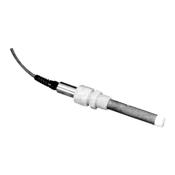
- Page 1 Shop online at (omega.com@j wwbv.omega.cum e-mail: info@omega. cor n STAMFORO.CT MAKCHESlEfl.UK CDE68 1 SERIES Conductivity/Resistivity Sensors...
- Page 2 M3594-0603-CDE681Series.qxd l/11/03 OMEGAnet@ Online Service USA : Certified 9001 Canada: For immediate technical or application assistance: and Canada: Mexico: Benelux: Czech Republic: France: Germany/Austria: United Kingdom: 9002 Ce rtifi ed It i s t h e po li cy o f OMEGA t o co m p l y w it h a ll wo rl dw i d e sa...
- Page 3 -ies.qxd 7/17/03 M3594-060%CDE681Ser CDE68 1 Series Conductivity/Resistivity Sensors IDENTIFIERS HELPFUL In addition to information on installation and operation, this instruction manual may contain WARNINGS pertaining to user safety, CAUTIONS regarding possible sensor malfunction, and NOTES on important, useful operating guidelines. 2:14 PM Page i warning looks like this.
-
Page 4: Table Of Contents
M3594-0603-CDEhElSeries.qxd 7/17/03 Table of Contents Part One - Introduction Part Two - Installation - Service and Maintenance Part Three 2:14 PM Page ii Section 1 General Information 1.1 Description: Benefits of Enhanced Performance Design ................Compatible Meters . - Page 5 M3594-0603-CDE681Series.qxd 7/17/03 CDE68 1 Series Conductivity/Resistivity Sensors List of Figures Figure 2-l General Dimensions and Cable Wire Details Figure 2-2 Insertion Mounting Details Fi ure 2-3 Corn Figure 2-4 Figure Table Table A 2:14 PM Page iii ression Fitting Parts Arrangement or Insertion R ounting .
- Page 6 M3594-0603-CDE681Series.qxd 7/17/03 2:14 PM Pageiv f-t-? CDE68 1 Series Conductivity/Resistivity Sensors ’ ‘ NOTES:...
-
Page 7: Part One - Introduction
The hardware material usually limits the system rating. Refer to Section 2 for complete specifications. 2:14 PM Page 1 CDE681 Part 1 compression fitting style sensors are manufactured to exacting Individually tested to determine its absolute cell constant (shown on its label as K = ), and its temperature element value (to the nearest 1.0 ohm). -
Page 8: Section 2 Specifications
M3594-0603mCDE681Series.qxd 7/17/03 CDE681 Part SECTION 2 - SPECIFICATIONS Wetted Materials. Maximum Temperature Maximum Pressure. Flow Rate. Temperature Compensator Sensor Cable: 2:14 PM Page 2 Introduction . Titanium electrodes (316 stainless steel outer electrode for extended sensor body style used with ball valve... -
Page 9: Part Two - Installation
Insertion Mounting 2. 1 To ensure optimum measurement performance, follow these guidelines when insertion mounting the sensor: 2:14 PM Page 3 CDE681 Part 2 CDE681-series compression fitting style sensor may be insertion mounted CONSTANT l/ 2 ’ 3 /4 ’... - Page 10 M3594-0603-CDE681Series.qxd 7/17/03 CDE681 Part 2 1. Install a pipe tee of appropriate size 2. Remove the compression fitting from the sensor and screw it into the pipe tee 3. Electrically connect sensor to analyzer. Refer to analyzer instruction manual 4. Calibrate analyzer using procedure in analyzer instruction manual.
- Page 11 1 to 1% turns. This should provide an effective process seal. Also, the crimped ferrule becomes a convenient reference indicator for insertion depth when re-inserting the sensor after cleaning. CDE681 Part 2 lnsta~~ation I ON...
- Page 12 M3594-0603-CDE681Series.qxd 7/17/03 CDE681 Part 2 - Installation Installation Tip! Re-using Compression Fitting, Nut, and Crimped Ferrule: If the sensor is re-installed, the compression fitting and nut can be re-used. The crimped ferrule, however, may need to be cut away from the sensor to remove it, making it unusable.
- Page 13 M3594-0603-CDE681Series.qxd l/17/03 Route the sensor cable through a pipe of an appropriate material and length. Screw the compression fitting onto the end of the pipe (or coupling, if used). 4. Fasten a Unilet junction box onto the other end of the pipe. 5.
-
Page 14: Section 3 Sensor/Interconnect Cable Details
M3594m0603mCDE681Series.qxd 7/17/03 CDL681 Part 2 - Installation SENSOR/INTERCONNECT CABLE DETAILS SECTION 3 Sensor Cable Details The sensor’ s integral cable is a 6-wire crosslinked polyethylene-jacketed cable with 4 conductors and two isolated shield wires. Refer to Figure 2-l for the function and color of each wire in the sensor ’... -
Page 15: Connecting Interconnect
M3594m0603mCDE681Series.qxd 7/17/03 5. Carefully position a sensor shield wire %-inch from the end as shown in Figure 2-6 to insulate and distinguish it from the inner shield wire. Doing this exposes X-inch of bare shield wire beyond the tubing or tape for connection purposes. 6. -
Page 16: Section 1 Recommended Cleaning Procedure
M3594&0603-CDE681Series.qxd 7/17/03 CDE681 Part 3 PART THREE - SERVICE AND MAINTENANCE SECTION 1 - RECOMMENDED CLEANING PROCEDURE Keep the sensor reasonably clean to maintain measurement accuracy. The time between cleanings (days, weeks, etc.) is affected by the characteristics of the process solution and can only be determined by operating experience. -
Page 17: F 2.1 Checking Sensor Operation
M3S94m0603-CDE681Series.qxd 7/17/03 Checking Sensor Operation Use the troubleshooting section in the analyzer instruction manual to determine whether the sensor or analyzer is in-operative. If you suspect the sensor, check it using this procedure: 1. Disconnect the sensor from the analyzer (or junction box, if using interconnect cable). -
Page 18: Customer Assistance
M3594-0603-CDE681Series.qxd 7/17/03 CDE681 Part 3 - Service and Maintenance Customer Assistance If you need assistance in troubleshooting or repair service, please contact your local OMEGA representative, or the OMEGA Customer Service Department at: l-800-633-2378 or l-203-359-1660. We can also be reached on the Internet at email: info at omega.com... - Page 19 OMEGA is a registered trademark of OMEGA ENGINEERING, INC. 0 Copyright 2003 OMEGA ENGINEERING, INC. All rights reserved. This document may not be copied, photocopied, reproduced, translated, or reduced to any electronic medium or machine-readable form, in whole or in part, without the prior written consent of OMEGA ENGINEERING, INC.
- Page 20 M3594-0603-CDE681Series.qxd l/17/03 Where Do Process Measurement and Control? TEMPERATURE m Wire: Thermocouple, RTD @ Calibrators @ Recorders, Controllers G? Infrared Pyrometers PRESSURE, STRAIN AND FORCE B’ [a Load Cells @ Displacement Transducers 0’ Instrumentation FLOW/LEVEL m Air Velocity Indicators II?t’ Ji? Totalizers pH/CONDUCTIVITY lZi’...