
Related Manuals for Meyer Sound RMServer

Summary of Contents for Meyer Sound RMServer
- Page 1 HARDWARE GUIDE COMPASS RMS RMServer Keep this important user guide. Check www.meyersound.com for updates.
- Page 2 Meyer Sound. MEYER SOUND and the Meyer Sound wave logo are trademarks of Meyer Sound Laboratories Inc. and are registered in the United States Patent and Trademark Office, as well as in other countries.
-
Page 3: Table Of Contents
Workflow for Compass RMS Configurations Chapter 2: Installing and Configuring RMServer About RMServer RMServer Features and Functions Installation and Mounting Setting Up an RMS Network with RMServer Connecting RMServer Configuring the RMServer Web Server Chapter 3: Connecting RMS Networks Network Specifications... - Page 4 Appendix A: Comparison of RMS Modules Appendix B: Troubleshooting RMS Problems Appendix C: External Muting and External Warning Relays Wiring RMServer for External Muting and External Warning Relays Configuring External Muting in the RMServer Web server Configuring Warning Relays in the RMServer Web Server...
-
Page 5: Chapter 1: Introduction
Compass control software. The RMS module stores the type of loudspeaker in which it is installed, a loudspeaker ID, and a user-assigned name. Some Meyer Sound loud- TIP: A tip offers a helpful tip relevant to the topic speakers come standard with an RMS module installed at hand. - Page 6 Compass software as icons or meter views with pop-up text displays; they are automatically added to Compass RMS Software System Require- the RMServer inventory and Compass Project. ments Compass RMS software runs as a tab within the Compass software environment.
-
Page 7: Workflow For Compass Rms Configurations
Mounting” on page 10 Transitioning from a Legacy iLON System 3. Attach RMServer to the computer’s Ethernet port or to a Upgrading from a legacy, iLON-based system to a Com- network router or network switch as described in the pass-based RMS network is not difficult. - Page 8 CHAPTER 1: INTRODUCTION ■ For loudspeakers requiring an UltraSeries RMS module, see “Installing the UltraSeries RMS Module” on page 37. To enable mute and solo capabilities in these loudspeak- ers, see “Installing the Mute Jumper on the UltraSeries RMS Module” on page 38. ■...
-
Page 9: Chapter 2: Installing And Configuring Rmserver
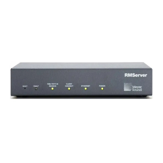
Relay Outputs: Alert conditions can be signaled to external devices by changing the state of two onboard relays. Figure 1: The RMServer front panel The RMServer front panel contains a Reset button and a +12V Output: Provides voltage for outboard contact closure number of indicators. -
Page 10: Installation And Mounting
+12 V, Inputs 1 and 2) are optically iso- lated from the RMServer circuitry. In addition, each To connect RMServer into your system and set up an RMS COM pin is isolated to allow for the use of appropri-... - Page 11 Connecting RMServer to the MPS-488HP Connecting RMServer directly to your computer If you are using only a single RMServer unit and no Galileo or other Meyer Sound device, you can connect it directly to your computer's Ethernet port. This is the simplest possible connection.
-
Page 12: Configuring The Rmserver Web Server
For more information on wiring and configuring RMServer for use with fire alarm muting systems, see Appendix C, “External Muting and External Warning Relays” Figure 5: RMServer can be reached from any browser by using its host name. CONFIGURING THE RMSERVER WEB SERVER Communication with RMServer by its host name is accom- plished using IPv6. - Page 13 IPv4 settings. In order for users employing IPv4 to communicate with RMServer, the computer, router, and RMServer all need to be set to the same IP network range. To set RMServer's IPv4 address: 1. Login to RMServer's web server page.
- Page 14 Fault)] Firmware Displays the firmware version currently running in RMServer. Basic Settings Figure 7: The Dashboard in RMServer's web server displays essential setup parameters for RMServer. Host and Network Information: Device Name: The name assigned by the user to the RMServer unit.
- Page 15 (**) take effect after RMServer has been restarted. Host Information and Network Information**: Device Name: The name that will appear for RMServer in the Network page of the RMS tab of Compass. [RMServer #n] Figure 9: The user name and password are edited in the Security Settings dialog.
- Page 16 Relay 2 Displays current settings for relay 1. SMTP Configuration: In order to send email notifications, RMServer must be configured to communicate with an (Set to trigger on (Speaker Offline) (Load Fault)) SMTP server than can send mail. These are the same...
- Page 17 Instantly (no threshold) Load faults repeat 3 times within 1 minute. Recovery Conditions Figure 12: The Advanced Settings page of RMServer's web server. This section provides check boxes for the conditions indi- NOTE: Changes to settings in this section that are...
- Page 18 RMServer problems, such There are four ways to restart RMServer. The front panel as a failed firmware update or an inability of RMServer to Reset button is recessed, so a paper clip or similarly small boot properly.
- Page 19 (along with updating instructions). If RMServer cannot load the most recent firmware when it boots up, it will try the previous version that was installed. If neither one works, it will boot into failsafe mode on its own.
- Page 20 CHAPTER 2: INSTALLING AND CONFIGURING RMSERVER...
-
Page 21: Chapter 3: Connecting Rms Networks
If the network is ■ Ethernet: Category 5 (Cat 5) or higher specification overloaded, critical data may reach the host com- puter very slowly, or not at all. Meyer Sound recom- NOTE: The maximum length for Ethernet mends that Ethernet-based RMS configurations be cables is 328 ft (100 m). -
Page 22: Ethernet Hubs And Switches
To reduce the amount of twisted-pair cabling in an RMS net- work, groups of neighboring loudspeakers can be daisy chained. In addition, a twisted-pair cable connected directly to RMServer can be spliced at a junction box or breakout panel with multiple outputs that can be patched to multiple loudspeaker destinations. -
Page 23: Design Tips For Rms Networks
■ Use a single twisted-pair run from the RMServer location to a breakout panel. Locate RMServer as close as possi- ble to the breakout panel, which should itself be located as close as possible to the loudspeakers. If you are receiving poor data or experiencing other com- ■... -
Page 24: Ethernet Configurations
Compass Control Software Mac or Windows Network Switch CAT 5E or Better Network Cable RMS FT-10 Twisted Pair Network Cable Belden® 8205 Figure 4: Basic RMS network with a single RMServer (top) and with multiple RMServers, Callisto, and a router (bottom). - Page 25 RMS USER GUIDE Compass Control Software Mac or Windows Intranet CAT 5E or Better Network Cable RMS FT-10 Twisted Pair Network Cable Belden® 8205 Figure 5: Basic Ethernet Configuration Using Existing Intranet Infrastructure...
- Page 26 In large systems, long cable runs can be required from an hotels, and theme parks, systems using multiple RMServers RMServer to the loudspeaker locations. One or more FTR- are preferred for increased network speed. 120 repeaters can be incorporated to extend the maximum cable run length.
- Page 27 RMS USER GUIDE Star Topology with Low Voltage Systems and Junction Point The MPS-488HP power supply is used in low-voltage sys- tems. It is important to note that each MPS-488HP con- sumes four RMS nodes, regardless of how many loudspeakers are actually connected to it. The junction point illustrates the flexibility of a free topology network.
- Page 28 CHAPTER 3: CONNECTING RMS NETWORKS...
-
Page 29: Chapter 4: Hp/Mp Rms Module
96 or a lower number require retrofitting. For informa- When equipped with an RMS module, Meyer Sound loud- tion, contact Meyer Sound Technical Services. speakers can be connected to an RMS network and moni- tored with Compass control software. - Page 30 CHAPTER 4: HP/MP RMS MODULE 2. To remove the amplifier from the loudspeaker cabinet: ■ While carefully removing the user panel, disconnect from the user panel the signal cable from the input board (with ■ Remove the eight large screws that secure the amplifier the gray connector), and disconnect from the AC mains to the cabinet.
- Page 31 RMS USER GUIDE ® ® module standoff), remove the paint with a Dremel tool 7. Apply one drop of Loctite to each of the four standoffs or sandpaper. Make sure to remove all debris from the on the HP/MP RMS module and then place the module chassis before proceeding.
- Page 32 CHAPTER 4: HP/MP RMS MODULE 8. Attach the short 9-wire gray ribbon cable from the 10. Attach the 26-pin connector from the long ribbon cable HP/MP RMS module to the connector on the power sup- to the HP/MP RMS module connector. Make sure to fully ply board.
-
Page 33: Installing The Mute Jumper On The Hp/Mp Rms Module
“ME” sticker on the HP/MP RMS user panel. Older RMS-equipped loudspeak- ers can be easily mute-enabled by installing the Mute Jumper, available from Meyer Sound in a mute jumper kit, P/N 476.005 RMS Mute Enable Replacement Upgrade Jumper. -
Page 34: Hp/Mp Rms User Panel
The NID should be discovered automatically by the damaged (contact Meyer Sound Technical Support). RMServer to which it is connected, but can be entered man- ually, if necessary. The NID for the HP/MP RMS module is located on the user panel below the orange RMS Network Service Button connectors (see Figure 8 on page 34). -
Page 35: Resetting The Hp/Mp Rms Module
3. After releasing the Reset button, continue holding down the Service button for 5 seconds. The HP/MP RMS mod- ule is reset and the loudspeaker is undiscovered and removed from the RMServer inventory. The HP/MP RMS module’s red Service LED blinks. - Page 36 CHAPTER 4: HP/MP RMS MODULE...
-
Page 37: Chapter 5: Ultraseries Rms Module
Acheron Studio NOTE: If you want to enable muting capability When equipped with an RMS module, Meyer Sound loud- for the loudspeaker, make sure to install the speakers can be connected to an RMS network and moni- Mute Jumper on the RMS module before installing it. -
Page 38: Installing The Mute Jumper On The Ultraseries Rms Module
“ME” sticker on the UltraSeries RMS user panel. Older RMS-equipped loud- speakers can be easily mute-enabled by installing the Mute Jumper, available from Meyer Sound in a mute jumper kit, P/ N 476.005 RMS Mute Enable Replacement Upgrade Copper strip Jumper. -
Page 39: Ultraseries Rms User Panel
You can simultaneously press the Reset and Service buttons to reset the UltraSeries RMS module, undiscover the loudspeaker, and remove it from the RMServer inventory (see “Resetting the UltraSeries RMS Module” on page 40). UltraSeries (UX) RMS Module Mute Jumper Pins... -
Page 40: Neuron Id For Ultraseries Rms Modules
Neuron ID (NID) that identifies the loudspeaker on the net- work. The NID should be discovered automatically by the RMServer to which it is connected, but can be entered man- ually, if necessary. The NID for the UltraSeries RMS module... -
Page 41: Chapter 6: Dx Rms Module
■ MJF-210 stage monitor (optional) MINA, and X-400C cannot be interchanged When equipped with an RMS module, Meyer Sound loud- with modules for other loudspeaker models. speakers can be connected to an RMS network and moni- tored with Compass control software. Some Meyer Sound... -
Page 42: Neuron Id For Dx Rms Modules
Each DX RMS module has a unique 12-character Neuron ID loudspeaker: (NID) that identifies the loudspeaker on the network. The NID should be discovered automatically by the RMServer to ■ During startup, the LED blinks 10 times. which it is connected, but can be entered manually, if neces- ■... -
Page 43: Chapter 7: Mx Rms Module
■ 1100-LFC loudspeaker (comes standard) driver. When equipped with an RMS module, Meyer Sound loud- To install the MX RMS module: speakers can be connected to an RMS network and moni- 1. Remove the loudspeaker’s AC power cable and audio tored with Compass control software. - Page 44 CHAPTER 7: MX RMS MODULE 4. Lift out the user panel. 7. Unplug the user panel from the primary AC mains PCMA board. Lift the user panel Lift to disconnect user panel from AC mains power 8. Disconnect the ribbon cable from the control card. NOTE: Make sure to hold the MX RMS module by its edges.
-
Page 45: Installing The Mute Jumper On The Mx Rms Module
Disconnect the user panel. Older RMS-equipped loudspeakers can be eas- power harness ily mute-enabled by installing the Mute Jumper, available from Meyer Sound in a mute jumper kit, P/N 476.005 RMS Mute Enable Replacement Upgrade Jumper.. Lift the connector ME Sticker... -
Page 46: Mx Rms User Panel
Each MX RMS module has a unique 12-character Neuron ID The Identify button serves the following functions: (NID) that identifies the loudspeaker on the network. The NID should be discovered automatically by the RMServer to If the loudspeaker has not yet been discovered (Wink/ ■... - Page 47 RMS USER GUIDE 4. After the Wink/Status LED blinks on and off, release the Identify button. The MX RMS module is reset and the loudspeaker is undiscovered and removed from the RMServer inventory.
- Page 48 CHAPTER 7: MX RMS MODULE...
-
Page 49: Chapter 8: Lyon Rms Module
This section documents installing the LYON RMS mod- ule.This installation procedure requires a standard #2 Phil- When equipped with an RMS module, Meyer Sound loud- lips screwdriver. speakers can be connected to an RMS network and moni- tored with Compass control software. -
Page 50: Lyon Rms User Panel
CHAPTER 8: LYON RMS MODULE 4. Remove the panel completely from the amplifier assem- 6. Install the new LYON RMS 4.1 module..bly (there should be enough room to reach the flat cable that connects the module to the digital control card.) LYON RMS USER PANEL NOTE: Make sure to hold the LYON RMS mod-... -
Page 51: Neuron Id For Lyon Rms Modules
Each LYON RMS module has a unique 12-character Neuron ID (NID) that identifies the loudspeaker on the network. The NID should be discovered automatically by the RMServer to which it is connected, but can be entered manually, if neces- sary. The NID for the LYON RMS module is located on the user panel below the orange RMS Network connectors (see Figure 1 on page 50). - Page 52 CHAPTER 8: LYON RMS MODULE 4. After the Wink/Status LED blinks on and off, release the Identify button. The LYON RMS module is reset and the loudspeaker is undiscovered and removed from the RMServer inventory.
-
Page 53: Chapter 9: Mps-488Hp External Power Supply With Rms
To undiscover the MPS-488HP and remove it from the ■ “The MPS-488HP in Compass Software” on page 54 RMServer inventory, press and hold the Identify button during startup (see “Resetting the MPS-488HP RMS NOTE: The RMS module is only available as a Module”... -
Page 54: Neuron Id For Mps-488Hp Rms Module
LED flashes continuously and flashes more rapidly with For the MPS-488HP to be recognized and identified by an increased data activity. RMServer, it must be powered on and connected to the net- ■ When the MPS-488HP is winked, either by clicking the work. -
Page 55: Appendix A: Comparison Of Rms Modules
APPENDIX A: COMPARISON OF RMS MODULES Table 3 documents the differences between the RMS modules. Loudspeakers with asterisks (*) come standard with the RMS module. Table 3: RMS Module RMS Module LEDs Buttons RMS Network Mute Connectors Enable HP/MP Service LED (Red): Service Button: 2 Weidmuller Jumper... - Page 56 APPENDIX A: COMPARISON OF RMS MODULES Table 3: RMS Module RMS Module LEDs Buttons RMS Network Mute Connectors Enable MPS-488HP Wink/Activity LED (Green): Identify Button: 2 Weidmuller None (HMS-5, HMS-10, HMS- ■ Blinks 10 ten times when powering up ■ Press to identify the MPS-488HP on connectors (Always...
-
Page 57: Appendix B: Troubleshooting Rms Problems
Enter. The computer’s IPv4 address, subnet mask, and default gateway are returned. 3. If the computer’s IPv4 address range does not match the RMServer’s and you want to change the address for the computer, do the following: ■ From the Windows taskbar, choose Start > Control ■... - Page 58 To verify RMServer’s IPv4 address: 1. From the Apple menu, choose System Preferences. 1. Access the RMServer web server from your browser as described in the section “Configuring the RMServer Web 2. Click the Network control panel to open it.
- Page 59 RMS USER GUIDE ■ The following example illustrates when the Ping com- ■ The following example illustrates when the Ping com- mand cannot reach its intended address, usually indicat- mand is returned successfully. The time for the Ping is ing an incorrect IPv4 address or a bad network indicated in milliseconds.
- Page 60 APPENDIX B: TROUBLESHOOTING RMS PROBLEMS ■ The following example illustrates when the Ping com- mand is not returned in the allowed time. Ping timeouts generally indicate a problem with the network, such that the network hardware is incorrectly configured, not pow- ered on, or not connected.
-
Page 61: Appendix C: External Muting And External Warning Relays
To ensure safety at venues with high-level sound reinforce- ment, some venues require automatic muting of audio sys- tems when a fire alarm or other emergency signal is triggered. RMServer can be configured for external muting of RMS-equipped devices when a fire alarm or external relay is triggered. -
Page 62: Wiring Rmserver For External Muting And External Warning Relays
12 MPS-488HP CAT 5E or Better Network Cable RMS FT-10 Twisted Pair Network Cable Belden® 8205 Figure 2: Connection diagram for relay operation of RMServer with external systems for fire alarm muting. Device with Contact Closure Opto Isolator Input... -
Page 63: Configuring External Muting In The Rmserver Web Server
RMServer's web server. For more information on config- mute functions to operate. uring onboard relay operation, see the section “Configur- ing Warning Relays in the RMServer Web Server” on To enable externally triggered muting by RMServer: page 64 and the section “Basic Settings” on page 14. -
Page 64: Configuring Warning Relays In The Rmserver Web Server
If you do not see the login page by 30 sec- onds after initiating restart, access the web server Figure 6: The Edit Relay setup dialog of RMServer’s web server. again from your browser and it will appear (assuming... -
Page 65: Email Notification For Externally Triggered Muting And Warning Relays
Figure 7: Email Notification section of the Basic Settings page of RMServer’s web server. Figure 8: Edit Email Notification dialog of RMServer’s web server. 3. To setup or change the events that trigger email notifica- tions and the email server and address configurations, click the Setup button in the Email Notification section to 8. - Page 66 APPENDIX C: EXTERNAL MUTING AND EXTERNAL WARNING RELAYS...
-
Page 67: Appendix D: Ftr-120 Free Topology Repeater
APPENDIX D: FTR-120 FREE TOPOLOGY REPEATER This chapter documents the FTR-120 Free Topology INSTALLING AND USING THE FTR-120 Repeater and includes the following topics: ■ “About the FTR-120” on page 67 FTR-120 Physical Installation “Installing and Using the FTR-120” on page 67 ■... - Page 68 APPENDIX D: FTR-120 FREE TOPOLOGY REPEATER When installing an FTR-120 network repeater on a Com- Network 1-4 are the network connections. Network 1 is the pass-based RMS network, avoid using the twisted wire ter- channel 1 network connection. Connect the first network minator (provided in the RMS peripheral kit) on the network twisted pair to the terminal block NET1 positions.
-
Page 69: Rms Configuration Sheet
RMS CONFIGURATION SHEET Customer Name Venue Date Loudspeaker Model Serial Number Neuron ID # Loudspeaker Name Notes/Location... - Page 71 MX RMS module 43 UltraSeries RMS module 38 email notifications 65 IPv4 address Ethernet computer 57 hubs 22 RMServer 58 switches 22 external muting 61 loudspeakers email notifications 65 DX RMS module 41 external warning relays 61, 64 HP/MP RMS module 29...
- Page 72 MPS-488HP 53 resetting 46 MX RMS module 46 user panel 46 UltraSeries RMS module 39 Wink/Activity LED 46 RMServer 5 connecting to a remote computer 10 Network connectors connecting to loudspeakers 11 DX RMS module 42 connecting to the MPS-488HP 11...
- Page 73 Service button 39 Service LED 39 user panel 39 verifying computer IPv4 address 57 network connections with Ping command 58 RMServer IPv4 address 58 Wink LED 6 DX RMS module 42 HP/MP RMS module 34, 40 LYON RMS module 51 MPS-488HP 54...
- Page 76 Meyer Sound Laboratories Inc. 2832 San Pablo Avenue Berkeley, CA 94702 www.meyersound.com © 2014 T: +1 510 486.1166 Meyer Sound Laboratories Inc. F: +1 510 486.8356 05.222.024.01 A...