
Related Manuals for Acer Extensa 5635


Summary of Contents for Acer Extensa 5635
- Page 1 Extensa 5635/5635Z/5235 Service Guide Service guide files and updates are available on the ACER/CSD web; for more information, please refer to http://csd.acer.com.tw...
- Page 2 PRINTED IN TAIWAN...
-
Page 3: Revision History
Revision History Please refer to the table below for the updates made to this Series service guide. Date Chapter Updates... - Page 4 Copyright Copyright © 2009 by Acer Incorporated. All rights reserved. No part of this publication may be reproduced, transmitted, transcribed, stored in a retrieval system, or translated into any language or computer language, in any form or by any means, electronic, mechanical, magnetic, optical, chemical, manual or otherwise, without the prior written permission of Acer Incorporated.
- Page 5 Conventions The following conventions are used in this manual: SCREEN MESSAGES NOTE WARNING CAUTION IMPORTANT Denotes actual messages that appear on screen. Gives bits and pieces of additional information related to the current topic. Alerts you to any damage that might result from doing or not doing specific actions.
- Page 6 DIFFERENT part number code to those given in the FRU list of this printed Service Guide. You MUST use the list provided by your regional Acer office to order FRU parts for repair and service of customer machines.
-
Page 7: Table Of Contents
System Block Diagram ......4 Acer Notebook tour ....... . . 5 Front View . - Page 8 LCD Assembly ......117 Extensa 5635/5635Z/5235 FRU List ....118 Screw List .
- Page 9 Model Definition and Configuration ....128 Extensa 5635/5635Z/5235 Series ....128 Test Compatible Components .
- Page 10 Table of Contents...
-
Page 11: System Specifications
• Intel® Pentium® mobile processor* • Intel® Celeron® mobile processor* • Mobile Intel® GM45/GL40 Express Chipset* • Acer InviLink™ Nplify™ 802.11b/g/Draft-N* • Acer InviLink™ 802.11b/g* System Memory • Dual-Channel SDRAM support • • Up to 2 GB of DDR3 800 MHz memory, upgradeable to 4 GB using two soDIMM modules* •... -
Page 12: Special Keys And Controls
Storage subsystem • 2.5" hard disk drive • DVD-Super Multi double-layer drive* • 5-in-1 card reader Communication • Integrated Acer Crystal Eye webcam • WLAN: • Intel® Wireless WiFi Link 5100/5300* • Acer InviLink™ Nplify™ 802.11b/g/Draft-N* • Acer InviLink™ 802.11b/g* •... - Page 13 Environment • Temperature: • Operating: 5 °C to 35 °C (41 °F to 95 °F) • Non-operating: -20 °C to 65 °C (-4 °F to 149°F) • Humidity (non-condensing): • Operating: 20% to 80% • Non-operating: 20% to 80% Chapter 1...
-
Page 14: System Block Diagram
System Block Diagram BOM MARK IV@: INT VGA EV@: STUFF FOR EXT VGA SP@: STUFF FOR UMA or VGA X'TAL 14.318MHz CLOCK GENERATOR ICS: SELGO: SLG8SP512TTR DDRIII Dual Channel DDR3 HDD (SATA) *1 Ext USB Port x 2 USB 0,1 ODD (SATA) Int USB Port x 1 USB 7... -
Page 15: Acer Notebook Tour
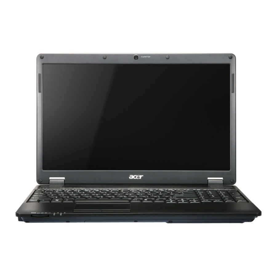
Acer Notebook tour Front View Icon Chapter 1 Item Acer Crystal Eye Web camera for video communication (only for webcam certain models). Display screen Also called Liquid-Crystal Display (LCD), displays computer output (Configuration may vary by models). Speakers Left and right speakers deliver stereo audio output. - Page 16 Click buttons The left and right buttons function like the left (left, center* and and right mouse buttons. right) *The center button serves as Acer Bio- Protection fingerprint reader supporting Acer FingerNav 4-way control function (only for certain models). Palmrest Comfortable support area for your hands when you use the computer.
-
Page 17: Hot Keys
Hot Keys The computer employs hotkeys or key combinations to access most of the computer's controls like screen brightness and volume output. To activate hotkeys, press and hold the <Fn> key before pressing the other key in the hotkey combination. Hotkey Icon <Fn>... -
Page 18: Rear View
Rear View Icon Left View Icon Item DC-in jack Connects to an AC adapter. Item Ethernet (RJ-45) Connects to an Ethernet 10/100/1000-based port network. Ventilation slots Enable the computer to stay cool, even after prolonged use. External display Connects to a display device (VGA) port (e.g. -
Page 19: Right View
Right View Icon Bottom View Icon Chapter 1 Item USB 2.0 port Connect to USB 2.0 devices (e.g. USB mouse, USB camera). Optical drive Internal optical drive; accepts CDs or DVDs. Optical disk access Lights up when the optical drive is active. indicator Optical drive eject Ejects the optical disk from the drive. - Page 20 Icon Item Battery lock Locks the battery in position. Ventilation slots Enable the computer to stay cool, even after and cooling fan prolonged use. Note: Do not cover or obstruct the opening of the fan. Description Chapter 1...
-
Page 21: Touchpad Basics
Touchpad Basics The following items show you how to use the touchpad: Move your finger across the touchpad (1) to move the cursor. • Press the left (2) and right (3) buttons located beneath the touchpad to perform selection and •... -
Page 22: Using The Keyboard
Using the Keyboard The keyboard has full-sized keys and an embedded numeric keypad, separate cursor, lock, Windows, function and special keys. Lock Keys and embedded numeric keypad The keyboard has three lock keys which you can toggle on and off. Lock key Caps Lock When Caps Lock is on, all alphabetic characters typed are in uppercase. -
Page 23: Windows Keys
Windows Keys The keyboard has two keys that perform Windows-specific functions. Windows key Pressed alone, this key has the same effect as clicking on the Windows Start button; it launches the Start menu. It can also be used with other keys to provide a variety of functions: : Open or close the Start menu <... -
Page 24: Special Key
Special Key You can locate the Euro symbol and the US dollar sign at the upper-center and/or bottom-right of your keyboard. The Euro symbol Open a text editor or word processor. Hold <Alt Gr> and then press the <5> key at the upper-center of the keyboard. NOTE: Note: Some fonts and software do not support the Euro symbol. -
Page 25: Acer Gridvista (Dual-Display Compatible)
Apply to confirm the new settings and click OK to complete the process. Acer GridVista is a handy utility that offers four pre-defined display settings so you can view multiple windows on the same screen. To access this function, please go to Start... -
Page 26: Hardware Specifications And Configurations
Hardware Specifications and Configurations Processor Item CPU Manufacturer CPU package Core Logic Chipset Features Processor Specifications Item Cores Speed P7450 2.13 GHz P8600 2.4 GHz P8700 2.53 GHz P9500 2.53 GHz T6400 2.0 GHz Specification Intel Micro-FCPGA packaging, 479-pin • NB Chipset Intel CS GM45NB / PM45NB •... - Page 27 Item Cores Speed T6600 2.2 GHz T9550 2.66 GHz T9600 2.8GHz T9800 2.93 GHz CPU Fan Tru Value Table CPU Temperature at Diode (°C) • Throttling 50%: On= 84°C; OFF=86°C • OS shut down at 100°C; H/W shut down(PH1) at 110°C Graphics Item Graphics...
- Page 28 Item External • 2048 x 1536: 75/60 Hz resolution/refresh • 1920 x 1440: 85/75/60 Hz rate • 1920 x 1200: 75/60 Hz • 1920 x 1080: 100/85/75/60 Hz • 1680 x 945: 100/85/75/60 Hz • 1600 x 1200: 120/100/85/75/60 Hz •...
- Page 29 Item Drive Format Disks Spindle speed 5400 (RPM) Performance Specifications Buffer size 8 MB Interface SATA Fast data transfer rate (Mbits/sec, max) Media data transfer rate (Mbytes/sec max) DC Power Requirements Voltage 5V ±5% tolerance Item Vendor & Hitachi Model Name HTS545032B9 A300 Capacity (GB)
- Page 30 Item Buffer size 8 MB Interface SATA Fast data transfer rate (Mbits/sec, max) Media data transfer rate (Mbytes/sec max) DC Power Requirements Voltage tolerance 5V ±5% Optical Disk Drive Item Manufacturer Sony 30656330, PLDS Corp., TS-L633B, Panasonic UJ880ADAA-A Type 8X DVD-Super Multi double-layer drive Performance Specification Transfer rate (MB/ 10.8...
- Page 31 Item Typical Power Consumption (watt) Weight (without inverter) Physical Size (mm) Electrical Interface Viewing Angle (degree) Horizontal (Right)/CR = 10 (Left) Vertical (Upper)/CR = 10 (Lower) Audio Interface Item Audio Controller Audio onboard or option Mono or Stereo Resolution Compatibility Sampling Rate.
- Page 32 Keyboard Item Type Total number of keypads Windows logo key Internal & external keyboard work simultaneously Mini Card Item Number Supported Features 3G Card Item Features Bluetooth interface Item Chipset Features Wireless LAN Item Type Features Battery Item Vendor & model name Battery Type Pack capacity Number of battery cell...
-
Page 33: System Utilities
System Utilities BIOS Setup Utility The BIOS Setup Utility is a hardware configuration program built into your computer’s BIOS (Basic Input/ Output System). Your computer is already properly configured and optimized, and you do not need to run this utility. However, if you encounter configuration problems, you may need to run Setup. -
Page 34: Information
Information The Information screen displays a summary of your computer hardware information. Information Main Security C P U T y p e C P U T y p e C P U S p e e d C P U S p e e d I D E 0 M o d e l N a m e : I D E 0 M o d e l N a m e : I D E 0 S e r i a l N u m b e r :... -
Page 35: Main
Main The Main screen allows the user to set the system time and date as well as enable and disable boot option and recovery. Information Main S y s t e m T i m e : S y s t e m T i m e : S y s t e m D a t e : S y s t e m D a t e : T o t a l M e m o r y :... -
Page 36: Security
Security The Security screen contains parameters that help safeguard and protect your computer from unauthorized use. Information Main Security S u p e r v i s o r P a s s w o r d I s : S u p e r v i s o r P a s s w o r d I s : U s e r P a s s w o r d I s : U s e r P a s s w o r d I s :... -
Page 37: Removing A Password
Setting a Password Follow these steps as you set the user or the supervisor password: Use the ↑ and ↓ keys to highlight the Set Supervisor Password parameter and press the Enter key. The Set Supervisor Password box appears: C o n f i r m N e w P a s s w o r d Type a password in the “Enter New Password”... -
Page 38: Changing A Password
Changing a Password Use the ↑ and ↓ keys to highlight the Set Supervisor Password parameter and press the Enter key. The Set Password box appears. E n t e r C u r r e n t P a s s w o r d C o n f i r m N e w P a s s w o r d Type the current password in the Enter Current Password field and press Enter. -
Page 39: Boot
Boot This menu allows the user to decide the order of boot devices to load the operating system. Bootable devices includes USB drives, the onboard hard disk drive and the DVD drive in the module bay. Information Main Security B o o t p r i o r i t y o r d e r : B o o t p r i o r i t y o r d e r : 1 . -
Page 40: Exit
Exit The Exit screen allows you to save or discard any changes you made and quit the BIOS Utility. Information Main Security E x i t S a v i n g C h a n g e s E x i t S a v i n g C h a n g e s E x i t D i s c a r d i n g C h a n g e s E x i t D i s c a r d i n g C h a n g e s L o a d S e t u p D e f a u l t s... -
Page 41: Bios Flash Utility
BIOS Flash Utility The BIOS flash memory update is required for the following conditions: • New versions of system programs • New features or options • Restore a BIOS when it becomes corrupted. Use the Flash16 utility to update the system BIOS flash ROM. NOTE: Do not install memory-related drivers (XMS, EMS, DPMI) when you use the Flash16 Utility. -
Page 42: Winflash Utility
WinFlash Utility Perform the following steps to use the WinFlash Utility: Copy the BIOS file into the Winflash folder. Double-click the WinFlash executable file. Chapter 2... - Page 43 Click OK to begin the update. A progress screen displays. When the process is complete, close all programs and applications and reboot the system. Chapter 2...
-
Page 44: Remove Hdd/Bios Password Utilities
Remove HDD/BIOS Password Utilities To reset a hard drive or BIOS password you require an additional PC. The utilities run on a DOS prompt on the second machine. This section provides instructions on how to remove a HDD password. If you enter the wrong hard drive password three times, the system reports the following error code: To reset the HDD password, run HDD_PW.EXE on a second machine as follows: At a command prompt, type hdd_pw 15494 0... - Page 45 Removing BIOS Passwords: If you key in the wrong Supervisor Password three times, System Disabled displays on the screen as below. To reset the BIOS password, run BIOS_PW.EXE on a second machine as follows: 1. At a command prompt, type bios_pw 14452 0. 2.
- Page 46 3. Reboot the system and type the selected string (in this example qjjg9vy or 07yqmjd etc.) for the BIOS user password. Cleaning BIOS Passwords To clear the password, perform the following steps: From a DOS prompt, Execute clnpwd.exe Press 1 or 2 to clean the desired password shown on the screen. The onscreen message determines whether the function is successful or not.
-
Page 47: Miscellaneous Utilities
Miscellaneous Utilities Using Boot Sequence Selector Boot Sequence Selector allows the boot order to be changed without accessing the BIOS. To use Boot Sequence Selector, perform the following steps: Enter into DOS. Execute BS.exe to display the usage screen. Select the desired boot sequence by entering the corresponding sequence, for example, enter BS2 to change the boot sequence to HDD|CD ROM|LAN|Floppy. -
Page 48: Using The Lan Mac Utility
Manufacturer (Type1, Offset04h): Acer Product Name (Type1, Offset05h): Aspire one xxxxx Serial Number (Type1, Offset07h): 01234567890123456789 UUID String (Type1, Offset08h): xxxxxxxx-xxxx-xxxx-xxxx-xxxxxxxxxxxx Asset Tag (Type3, Offset04h): Acer Asstag Example 2: Write Product Name to EEPROM Input: dmitools /wp Acer Example 3: Write Serial Number to EEPROM... -
Page 49: Machine Disassembly And Replacement
Machine Disassembly and Replacement This chapter contains step-by-step procedures on how to disassemble the notebook computer for maintenance and troubleshooting. Disassembly Requirements To disassemble the computer, you need the following tools: Wrist grounding strap and conductive mat for preventing electrostatic discharge •... -
Page 50: General Information
General Information Pre-disassembly Instructions Before proceeding with the disassembly procedure, make sure that you do the following: Turn off the power to the system and all peripherals. Unplug the AC adapter and all power and signal cables from the system. Place the system on a flat, stable surface. -
Page 51: External Module Disassembly Process
External Module Disassembly Process External Modules Disassembly Flowchart Remove RTC Battery Screw List Step Lower Door M2.5*5 ODD Module M2.5*5 ODD Bracket M2*3 HDD Carrier M3*3 WLAN Module M2.5*4 Chapter 3 Turn off system and peripherals power Disconnect power and signal cables from system Remove Battery... -
Page 52: Removing The Battery Pack
Removing the Battery Pack Turn the computer over. Slide the battery lock to the unlocked position. Slide and hold the battery release latch to the release position (1), then lift out the battery pack from the main unit (2). Chapter 3... -
Page 53: Removing The Sd Dummy Card
Removing the SD Dummy Card Push the SD Dummy Card all the way in to eject it. Pull the card out from the slot. Chapter 3... -
Page 54: Removing The Lower Door
Removing the Lower Door See “Removing the Battery Pack” on page 42. Remove the eight screws securing the Lower Door to the Lower Cover. Step Lower Door M2.5*5 Remove the Lower Door as shown. Size Quantity Screw Type Chapter 3... -
Page 55: Removing The Rtc Battery
Removing the RTC Battery IMPORTANT: Follow local regulations for disposal of all batteries. See “Removing the Lower Door” on page 44. IMPORTANT: Do not pry the battery out of the socket. Using force may permanently damage the battery socket. Slide the RTC Battery to the right to release the securing clips in the battery socket. Lift the battery clear of the socket. -
Page 56: Removing The Optical Drive Module
Removing the Optical Drive Module See “Removing the Lower Door” on page 44. Remove the single screw securing the ODD Module. Step ODD Module M2.5*5 Insert a suitable object in to the Lower Cover to push the ODD Module clear of the casing. Pull the ODD Module out of the chassis. - Page 57 Remove the two screws securing the ODD Bracket and remove the ODD bracket from the module. Step ODD Bracket M2*3 Insert a pin in the eject hole of the ODD to eject the ODD tray. Press down on the locking catch to release the ODD cover and remove. Chapter 3 Size Quantity...
-
Page 58: Removing The Hard Disk Drive Module
Removing the Hard Disk Drive Module See “Removing the Lower Door” on page 44. Use the pull-tab to slide the HDD in the indicated direction and disconnect the interface. Lift the hard disk drive module out of the bay, right side first as shown. NOTE: To prevent damage to device, avoid pressing down on it or placing heavy objects on top of it. - Page 59 Remove the two screws securing the hard disk to the carrier. Step HDD Carrier M3*3 Remove the HDD from the carrier. Chapter 3 Size Quantity Screw Type...
-
Page 60: Removing The Dimm Modules
Removing the DIMM Modules See “Removing the Lower Door” on page 44. Push out the release latches on both sides of the DIMM socket to release the DIMM module. Remove the DIMM module. Repeat steps for the second DIMM module. Chapter 3... -
Page 61: Removing The Wlan Module
Removing the WLAN Module See “Removing the Lower Door” on page 44. Disconnect the Antenna cables from the WLAN Module. NOTE: The black cable attaches to the MAIN terminal and the white cable attaches to the AUX terminal. NOTE: When reattaching the antennas, ensure the cables are tucked into the chassis to prevent damage. Remove the two screws securing the WLAN Module to the Mainboard Step WLAN Module... - Page 62 Detach the WLAN Module from the WLAN socket. Chapter 3...
-
Page 63: Main Unit Disassembly Process
Main Unit Disassembly Process Main Unit Disassembly Flowchart Remove External Modules before proceeding Upper Cover Remove TouchPad Bracket Screw List Step Switch Cover M2.5*2 M2.5*5 LCD Module M2.5*5 Upper Cover M2.5*5 M2.5*4 TouchPad Bracket M2.5*3 Speaker Module M2.5*3 Bluetooth Board M2*3 USB Board M2.5*5... -
Page 64: Removing The Switch Cover
Removing the Switch Cover See “Removing the Battery Pack” on page 42. Remove the five screws securing the Switch Cover to the Upper Cover. NOTE: The screws marked with green callouts are also marked on the Lower Cover with the letters KB. Step Switch Cover M2.5*2... - Page 65 Turn the computer over and open the LCD Panel to the full extent. IMPORTANT: Do not use metal tools to remove the Switch Cover. Using metal tools may permanently damage the casing. Insert a suitable plastic tool in to the cutout located above the keypad Num Lock key, and pry the Switch Cover away from the Upper Cover as shown.
-
Page 66: Removing The Keyboard
Removing the Keyboard See “Removing the Switch Cover” on page 54. Lift the centre of Keyboard up as shown to release the four securing clips on the Upper Cover. IMPORTANT: Do not remove the Keyboard from the computer; the Keyboard FFCs are still connected. Turn the Keyboard over and place it on the TouchPad. -
Page 67: Removing The Lcd Module
Removing the LCD Module See “Removing the Keyboard” on page 56. Turn the computer over. Remove the two screws securing the LCD Module to the Lower Cover. Step LCD Module M2.5*5 Remove the Antenna cables from the cable channel. Ensure that the cables are free from all cable clips. Chapter 3 Size Quantity... - Page 68 Pull the Antenna cables through the Upper Cover as shown. Ensure that the Antennas are completely free from the cover. Remove the Antenna from the cable channel all the way to the Hinge Well. Ensure that the cables are free from all cable clips.
- Page 69 Remove the LVDS cable from the cable channel all the way to the Hinge Well. Ensure that the cable is free from the cable clip. Remove the four screws securing the LCD Module to the Lower Cover. Step LCD Module M2.5*5 Using both hands, lift the LCD Module clear of the Lower Cover.
-
Page 70: Removing The Upper Cover
Removing the Upper Cover IMPORTANT: The TouchPad is supplied as part of the Upper Cover. If the TouchPad is defective, replace the entire Upper Cover. See “Removing the LCD Module” on page 57. Turn the computer over. Remove the eighteen screws on the bottom panel. Step Upper Cover M2.5*5... - Page 71 Disconnect A as shown. Disconnect B as shown. Open the locking latch on C and disconnect the FFC from the Mainboard. Chapter 3...
- Page 72 Remove the eleven screws securing the Upper Cover to the Lower Cover. Step Upper Cover M2.5*4 Remove the Upper Cover, right side first as shown. Size Quantity Screw Type Chapter 3...
-
Page 73: Removing The Touchpad Bracket
Removing the TouchPad Bracket IMPORTANT: The TouchPad is supplied as part of the Upper Cover. If the TouchPad is defective, replace the entire Upper Cover. See “Removing the Upper Cover” on page 60. Remove the two screws securing the bracket to the Upper Cover. Step TouchPad M2.5*3... - Page 74 Open the locking latch and remove the TouchPad FFC as shown. Lift the protective sheet away from the Upper Cover to expose the TouchPad FFC as shown. Peel the FFC away from the protective cover and remove the cable from the Upper Cover. Chapter 3...
-
Page 75: Removing The Speaker Module
Removing the Speaker Module See “Removing the Upper Cover” on page 60. Lift the protective sheet away from the Upper Cover to expose the Microphone and Speaker cables as shown. Remove the Microphone cable from the first two cable clips as shown. Remove the left speaker cable from the cable channel. - Page 76 Remove the right speaker cable from the cable channel. Ensure that the cable is free from all cable clips. Chapter 3...
- Page 77 Turn the Upper Cover over and remove the speaker cable from the cable clip as shown. Remove the two screws (one each side) securing the Speaker Modules to the Upper Cover. Step Speaker Module M2.5*3 Remove the Speaker Modules from the Upper Cover as shown. Chapter 3 Size Quantity...
-
Page 78: Removing The Microphone
Removing the Microphone See “Removing the Speaker Module” on page 65. Remove the Microphone cable from the cable channel. Ensure that the cable is free from all cable clips. Turn the Upper Cover over and remove the cable from the cable clip as shown. Lift the Microphone clear of the Upper Cover. -
Page 79: Removing The Bluetooth Board
Removing the Bluetooth Board See “Removing the Upper Cover” on page 60. Disconnect the Bluetooth cable from the Mainboard. Disconnect the Bluetooth cable from the Bluetooth Board. Chapter 3... - Page 80 Remove the single screw securing the Bluetooth Board to the Lower Cover. Step Bluetooth Board M2*3 Remove the Bluetooth Board from the Lower Cover. Size Quantity Screw Type Chapter 3...
-
Page 81: Removing The Usb Board
Removing the USB Board See “Removing the Upper Cover” on page 60. Open the locking latch on the FFC and disconnect it from the Mainboard. Open the locking latch on the FFC and disconnect it from the USB Board. Remove the adhesive tape securing the USB FFC to the Lower Cover and remove the cable. Chapter 3... - Page 82 Remove the two screws securing the USB Board to the Lower Cover. Step USB Board M2.5*5 Remove the USB Board from the Lower Cover as shown. Size Quantity Screw Type Chapter 3...
-
Page 83: Removing The Mainboard
Removing the Mainboard See “Removing the Hinge Supports” on page 75. Turn the computer over. Disconnect the power cable from the Mainboard as shown. Remove the single screw securing the Mainboard to the Lower Cover. Step Mainboard M2.5*5 Chapter 3 Size Quantity Screw Type... - Page 84 Rotate the Mainboard upward and remove it from the chassis, right side first. Place the Mainboard on a clean, dust-free surface. Chapter 3...
-
Page 85: Removing The Hinge Supports
Removing the Hinge Supports See “Removing the Mainboard” on page 73. Remove the four screws (one on the left and three on the right) securing the Hinge Supports to the Lower Cover. Step Hinge Supports M2.5*4 Lift the Hinge Supports clear of the Lower Cover. Chapter 3 Size Quantity... -
Page 86: Removing The Thermal Module
Removing the Thermal Module See “Removing the Mainboard” on page 73. Disconnect the fan cable from the Mainboard. Loosen the six captive screws (in reverse numerical order from screw 6 to screw 1) securing the Thermal Module in place. Lift the Thermal Module clear of the Mainboard. Chapter 3... -
Page 87: Removing The Cpu
Removing the CPU See “Removing the Thermal Module” on page 76. Turn the securing screw 180° to release the CPU from the socket. Remove the CPU from the socket as shown. IMPORTANT: The pins on the underside of the CPU are very delicate. If they are damaged, the CPU may malfunction. -
Page 88: Lcd Module Disassembly Process
LCD Module Disassembly Process IMPORTANT:Cable paths and positioning may not represent the actual model. During the removal and replacement of components, ensure all available cable channels and clips are used and that the cables are replaced in the same position. LCD Module Disassembly Flowchart LCD FPC Cable Screw List... -
Page 89: Removing The Lcd Bezel
Removing the LCD Bezel See “Removing the LCD Module” on page 57. Remove the six screw caps and screws from the LCD Bezel. Step LCD Bezel M2.5*5 Starting from the inside bottom edge, pry the Bezel away from the panel. Continue up the sides as shown. If necessary, use a plastic pry to release the corners of the Bezel. - Page 90 Lift up the Bezel and remove it from the LCD Module. Chapter 3...
-
Page 91: Removing The Lcd Panel
Removing the LCD Panel See “Removing the LCD Bezel” on page 79. Remove the four securing screws from the LCD Panel. Step LCD Panel M2.5*5 Lift the LCD Panel, front edge first, and turn it over to expose the Camera cable. Chapter 3 Size Quantity... - Page 92 Disconnect the Camera cable and remove the LCD Panel. Chapter 3...
-
Page 93: Removing The Fpc Cable And Lcd Brackets
Removing the FPC Cable and LCD Brackets See “Removing the LCD Panel” on page 81. Lift the cable away from the LCD Panel to detach the adhesive securing it in place. Carefully lift the adhesive tape securing the cable to the panel. Chapter 3... - Page 94 Disconnect the cable from the LCD panel as shown. Remove the six securing screws (three each side) from the LCD Panel brackets. Step LCD Brackets M2*3 Remove the brackets from the LCD Panel. Size Quantity Screw Type Chapter 3...
-
Page 95: Removing The Camera Board
Removing the Camera Board See “Removing the LCD Panel” on page 81. Remove the Camera Board from the LCD Module. Chapter 3... -
Page 96: Lcd Module Reassembly Procedure
LCD Module Reassembly Procedure Replacing the Camera Board Ensure that the locating pins are correctly positioned and place the Camera Board in the LCD Module. Press down to secure it in place Chapter 3... -
Page 97: Replacing The Lcd Brackets And Fpc Cable
Replacing the LCD Brackets and FPC Cable Secure the brackets to the panel using six bracket screws (three each side). Insert the LCD Cable into the panel connector as shown. Replace the LCD cable as shown. Press down as indicated to secure the cable in place. Chapter 3 Secure the connector by replacing the adhesive strip as shown. - Page 98 IMPORTANT:Ensure that the LCD Cable runs as shown to avoid trapping when the Bezel is replaced. Chapter 3...
-
Page 99: Replacing The Lcd Panel
Replacing the LCD Panel Place the LCD Panel adjacent to the LCD Cover and reconnect the Camera cable. Turn the panel over and place it in the LCD Cover. IMPORTANT: Ensure that the cables are not trapped under the panel. Replace the four screws to secure the panel in place. -
Page 100: Replacing The Lcd Bezel
Replacing the LCD Bezel Place the Bezel onto the LCD Module ensuring that the cables exit the module as shown and are not trapped between the bezel and the cover. Press down around the perimeter of the Bezel to snap it in to place. Replace the six screws and screw caps for the LCD Bezel. -
Page 101: Troubleshooting
Common Problems Use the following procedure as a guide for computer problems. NOTE: The diagnostic tests are intended to test only Acer products. Non-Acer products, prototype cards, or modified options can give false errors and invalid system responses. Obtain the failing symptoms in as much detail as possible. -
Page 102: Power On Issue
Power On Issue If the system doesn’t power on, perform the following actions one at a time to correct the problem. Do not replace a non-defective FRU: Computer Shuts Down Intermittently If the system powers off at intervals, perform the following actions one at a time to correct the problem. Check the power cable is properly connected to the computer and the electrical outlet. -
Page 103: No Display Issue
No Display Issue If the Display doesn’t work, perform the following actions one at a time to correct the problem. Do not replace a non-defective FRUs: No POST or Video If the POST or video doesn’t display, perform the following actions one at a time to correct the problem. Make sure that the internal display is selected. -
Page 104: Abnormal Video Display
Remove the drives (see “Disassembly Process” on page 40). If the Issue is still not resolved, see “Online Support Information” on page 185. Abnormal Video Display If video displays abnormally, perform the following actions one at a time to correct the problem. Reboot the computer. -
Page 105: Random Loss Of Bios Settings
Random Loss of BIOS Settings If the computer is experiencing intermittent loss of BIOS information, perform the following actions one at a time to correct the problem. If the computer is more than one year old, replace the CMOS battery. Run a complete virus scan using up-to-date software to ensure the computer is virus free. -
Page 106: Lcd Failure
LCD Failure If the LCD fails, perform the following actions one at a time to correct the problem. Do not replace a non- defective FRUs: Chapter 4... -
Page 107: Built-In Keyboard Failure
Built-In Keyboard Failure If the built-in Keyboard fails, perform the following actions one at a time to correct the problem. Do not replace a non-defective FRUs: Chapter 4... -
Page 108: Touchpad Failure
TouchPad Failure If the TouchPad doesn’t work, perform the following actions one at a time to correct the problem. Do not replace a non-defective FRUs: Chapter 4... -
Page 109: Internal Speaker Failure
Internal Speaker Failure If the internal Speakers fail, perform the following actions one at a time to correct the problem. Do not replace a non-defective FRUs: Sound Problems If sound problems are experienced, perform the following actions one at a time to correct the problem. Reboot the computer. - Page 110 Restore system and file settings from a known good date using System Restore. If the issue is not fixed, repeat the preceding steps and select an earlier time and date. 10. Reinstall the Operating System. 11. If the Issue is still not resolved, see “Online Support Information” on page 185. Chapter 4...
-
Page 111: Internal Microphone Failure
Internal Microphone Failure If the internal Microphone fails, perform the following actions one at a time to correct the problem. Do not replace a non-defective FRUs: Microphone Problems If internal or external Microphones do no operate correctly, perform the following actions one at a time to correct the problem. -
Page 112: Hdd Not Operating Correctly
HDD Not Operating Correctly If the HDD does not operate correctly, perform the following actions one at a time to correct the problem. Disconnect all external devices. Run a complete virus scan using up-to-date software to ensure the computer is virus free. Run the Windows Vista Startup Repair Utility: insert the Windows Vista Operating System DVD in the ODD and restart the computer. -
Page 113: Usb Failure (Rightside)
USB Failure (Rightside) If the rightside USB port fails, perform the following actions one at a time to correct the problem. Do not replace a non-defective FRUs: Chapter 4... -
Page 114: External Mouse Failure
External Mouse Failure If an external Mouse fails, perform the following actions one at a time to correct the problem. Try an alternative mouse. If the mouse uses a wireless connection, insert new batteries and confirm there is a good connection. See the mouse user manual. -
Page 115: Other Failures
Issue” on page 92): Power-off the computer. Visually check them for damage. If any problems are found, replace the FRU. Remove or disconnect all of the following devices: • Non-Acer devices • Printer, mouse, and other external devices • Battery pack •... -
Page 116: Post Code Reference Tables
POST Code Reference Tables These tables describe the POST codes and components of the POST process. Chipset POST Codes The following table details the chipset POST codes and functions used in the POST. Code Beeps 1-2-2-3 8254 8237 1-3-1-1 1-3-1-3 1-3-4-1 1-3-4-3 1-4-1-1... - Page 117 Code Beeps 2-1-2-3 2-2-3-1 Chapter 4 POST Routine Description Advanced configuration of chipset registers Load alternate registers with CMOS values Initialize interrupt vectors POST device initialization Check ROM copyright notice Check video configuration against CMOS Initialize PCI bus and devices Initialize all video adapters in system QuietBoot start (optional) Shadow video BIOS ROM...
- Page 118 Code Beeps POST Routine Description Configure Motherboard Configurable Devices (optional) Initialize BIOS Data Area Enable Non-Maskable Interrupts (NMIs) Initialize Extended BIOS Data Area Test and initialize PS/2 mouse Initialize floppy controller Determine number of ATA drives (optional) Initialize hard-disk controllers Initialize local-bus hard-disk controllers Jump to UserPatch2 Build MPTABLE for multi-processor boards...
- Page 119 Code Beeps Code Beeps * If the BIOS detects error 2C, 2E, or 30 (base 512K RAM error), it displays an additional word-bitmap (xxxx) indicating the address line or bits that failed. For example, 2C 0002 means address line 1 (bit one set) has failed.
- Page 120 Chapter 4...
-
Page 121: Jumper And Connector Locations
U5 / CPU thermal IC Glide PAD FFC Conn PU3 / Charge PWM IC Y3/ KBC X’tal U14/ EC/ KBC CN9/ BT wire U17 System BIOS CN8 / Ext USB wire Conn U16 Acer ID ROM Glide PAD Right SW Y4 S.B X’tal. -
Page 122: Bottom View
Bottom View CN9 / LAN Conn U24 DIS HDCP ROM U23 Dis Spectrum IC U27 / N10 VGA IC U25 / U27 Dis VRAM IC. U9 / CRT Switch IC CN11 / CRT Conn CN14 /FAN Conn CN15 / HDMI Conn. CN16 / USB CN18 / EXT Mic conn CN21 / EXT HP... -
Page 123: Steps For Clearing Bios Password Check
Clearing Password Check and BIOS Recovery This section provides you the standard operating procedures of clearing password and BIOS recovery for Extensa 5635/5635Z/5235. Extensa 5635/5635Z/5235 provides one Hardware Open Gap on main board for clearing password check, and one Hotkey for enabling BIOS Recovery. -
Page 124: Bios Recovery By Crisis Disk
BIOS Recovery by Crisis Disk BIOS Recovery Boot Block: BIOS Recovery Boot Block is a special block of BIOS. It is used to boot up the system with minimum BIOS initialization. Users can enable this feature to restore the BIOS firmware to a successful one if a previous BIOS flashing process fails. -
Page 125: Fru (Field Replaceable Unit) List
DIFFERENT part number code from those given in the FRU list of this printed Service Guide. You MUST use the local FRU list provided by your regional Acer office to order FRU parts for repair and service of customer machines. -
Page 126: Extensa 5635/5635Z/5235 Exploded Diagrams
Extensa 5635/5635Z/5235 Exploded Diagrams Main Assembly Item Description Keyboard Switch Cover Upper Cover Battery Mainboard Thermal Module Part Number Item Description KB.INT00.105 ODD Bezel 42.EDW07.001 ODD Module 60.EDM07.001 BT.00607.072 Lower Cover MB.EDX06.001 Lower Door 60.EDR07.002 Part Number 42.EDM07.003 6M.EDM07.001 KH.16004.006 60.EDM07.002... -
Page 127: Lcd Assembly
LCD Assembly Item LCD Cover LCD Bracket_L LCD Bezel LCD Cable LCD Bracket_R LCD Panel Chapter 6 Description Part Number 60.EDM07.003 33.EDM07.003 60.EDR07.001 50.EDM07.005 33.EDM07.002 LK.15605.003... -
Page 128: Extensa 5635/5635Z/5235 Fru List
Extensa 5635/5635Z/5235 FRU List CATEGORY Adapter Adapter DELTA 65W 19V 1.7x5.5x11 Yellow ADP-65JH DB A, LV5 LED LF Adapter LITE-ON 65W 19V 1.7x5.5x11 Yellow PA-1650- 22AC LV5 LED LF Adapter HIPRO 65W 19V 1.7x5.5x11 Yellow HP- A0652R3B 1LF, LV5 LED LF... - Page 129 CPU Intel Pentium Dual-Core T4200 PGA 2.0G 1M 800 35W R-0 no VT CPU Intel Core2Dual T6570 PGA 2.1G 2M 800 R-0 CPU Intel Core2Dual T6600 PGA 2.2G 2M 800 35W R-0 Chapter 6 PARTNAME ACER P/N 50.EDM07.001 50.EDM07.002 50.EDM07.003 50.EDM07.004 42.EDW07.001 42.EDM07.001...
- Page 130 HDD HGST 2.5" 5400rpm 320GB HTS545032B9A300 Panther B SATA LF F/W: C60F HDD WD 2.5" 5400rpm 320GB WD3200BEVT-22ZCT0 ML160 SATA LF F/W:11.01A11 HDD WD 2.5" 5400rpm 500GB WD5000BEVT-22ZAT0 ML250 SATA LF F/W:01.01A01 HDD BRACKET PARTNAME ACER P/N 6M.EDM07.001 KU.00807.064 KU.00801.030 KU.0080E.017 KU.0080F.004 33.PDA07.003 42.EDM07.003 33.PDA07.003...
- Page 131 Keyboard 17KB-FV2 Tangiz/Texcoco 106KS Black Brazilian Portuguese Keyboard 17KB-FV2 Tangiz/Texcoco 106KS Black Belgium Keyboard 17KB-FV2 Tangiz/Texcoco 105KS Black Arabic/English Keyboard 17KB-FV2 Tangiz/Texcoco 106KS Black Nordic Chapter 6 PARTNAME ACER P/N KB.INT00.105 KB.INT00.106 KB.INT00.107 KB.INT00.108 KB.INT00.109 KB.INT00.110 KB.INT00.111 KB.INT00.112 KB.INT00.115 KB.INT00.116 KB.INT00.117...
- Page 132 220nit 8ms 500:1 LCD CABLE 15.6 IN. W/CCD LCD COVER ASSY W/ANTENNA LCD BEZEL ASSY W/CCD LCD BRACKET W/HINGE - R LCD BRACKET W/HINGE - L CCD MODULE 0.3M PARTNAME ACER P/N KB.INT00.217 KB.INT00.114 KB.INT00.130 KB.INT00.215 6M.EDR07.001 LK.15605.003 LK.15606.003 LK.15608.002 LK.1560D.005...
- Page 133 LED LCD SAMSUNG 15.6"W WXGA Glare LTN156AT02-A01 LF 220nit 8ms 500:1 LED LCD LPL 15.6"W WXGA Glare LP156WH2-TLE1 LF 220nit 8ms 400:1 LED LCD CMO 15.6"W WXGA Glare N156B6-L04 LF 220nit 8ms 500:1 Chapter 6 PARTNAME ACER P/N 6M.EDR07.002 LK.15605.005 LK.15606.002 LK.15608.005 LK.1560D.006 50.EDM07.005 60.EDM07.003 60.EDR07.001...
- Page 134 LCD CABLE 15.6 IN W/O CCD LCD CABLE 15.6 IN. W/CCD LCD COVER ASSY W/ANTENNA LCD BEZEL ASSY W/O CCD LCD BRACKET W/HINGE - R LCD BRACKET W/HINGE - L PARTNAME ACER P/N 50.EDM07.006 60.EDM07.003 60.EDM07.004 33.EDM07.002 33.EDM07.003 6M.EDM07.003 LK.15605.005 LK.15606.002...
- Page 135 M471B5673EH1-CF8 LF 128*8 0.055um Thermal Module THERMAL MODULE - DIS THERMAL MODULE - UMA Miscellaneous LCD BEZEL RUBBER RUBBER FOOT -C Speaker SPEAKER SPEAKER - HALOGEN-FREE Chapter 6 PARTNAME ACER P/N MB.EDX06.001 MB.EDU06.001 MB.EDY06.001 MB.EDR06.001 KN.1GB09.011 KN.1GB0B.019 KN.1GB0G.019 KN.1GB0B.028 KN.2GB09.004 KN.2GB0G.009 KN.2GB0B.005 KN.2GB0B.012...
-
Page 136: Screw List
SCREW SCREW M3*0.5+3.5I SCREW SCREW M2.5*3.0-I(BZN) SCREW SCREW M2.5*6.0-P(NI)(NYLOK)IRON SCREW SCREW M2.5*2-I (NI,NYLOK)IRON SCREW SCREW M2.5*4.0-I(BUWZN)(NYLON PATCH)IRON SCREW SCREW M2.5*5.0-I(BZN) SCREW SCREW M2.0*3.0-I(BKAG)(NYLOK) IRON SCREW SCREW M3*0.5+3.5I PARTNAME ACER P/N 86.A03V7.006 86.TPK07.003 86.EDM07.001 86.EDM07.002 86.EDM07.003 86.ARE07.003 86.ARE07.002 86.TDY07.003 Chapter 6... - Page 137 Chapter 6...
-
Page 138: Model Definition And Configuration
Model Definition and Configuration Extensa 5635/5635Z/5235 Series Model Country EX5235- EMEA Middle East 901G16Mn EX5235- 901G16Mn EX5235- EMEA Switzerland 902G16Mn EX5235- EMEA Luxembourg 902G16Mn EX5235- EMEA Austria 902G16Mn EX5235- EMEA Middle East 902G16Mn EX5235- EMEA Czech 902G16Mn EX5235- EMEA Belgium... - Page 139 Hungary 902G16Mn EX5235- EMEA Sweden 902G16Mn EX5235- EMEA Russia 902G16Mi EX5235- EMEA Luxembourg 902G16Mn Acer Part No Description LX.EDP0Y.062 EX5235-902G16Mn VHB32EREU7 MC UMAkk 1*2G/160/6L/5R/ CB_bgn_AN_SL11 LX.EDP0Y.060 EX5235-902G16Mn VHB32ERFR1 MC UMAkk 1*2G/160/6L/5R/ CB_bgn_AN_FR21 LX.EDP0Y.051 EX5235-902G16Mn EM VHB32ERME3 MC UMAkk 1*2G/ 160/6L/5R/CB_bgn_AN_FR22 LX.EDP0Y.061...
- Page 140 EX5235- EMEA Turkey 902G16Mn EX5235- EMEA Greece 902G16Mn EX5235- EMEA Middle East 902G16Mn Appendix A Acer Part No Description LX.EDP0Y.037 EX5235-902G16Mn VHB32ERIL1 MC UMAkk 1*2G/160/6L/5R/ bgn_AN_HE13 LX.EDP0Y.036 EX5235-902G16Mn VHB32ERGB1 MC UMAkk 1*2G/160/6L/5R/ bgn_AN_EN12 LX.EDP0Y.033 EX5235-902G16Mn VHB32ERFI2 MC UMAkk 1*2G/160/6L/5R/ bgn_AN_FI11 LX.EDP0Y.032...
- Page 141 902G16Mn EX5235- EMEA Middle East 901G16Mn EX5235- EMEA Germany 901G16Mn EX5235- EMEA Denmark 901G16Mn Acer Part No Description LX.EDP0Y.018 EX5235-902G16Mn VHB32ERIT1 MC UMAkk 1*2G/160/6L/5R/ bgn_AN_IT11 LX.EDP0Y.016 EX5235-902G16Mn VHB32ERNO1 MC UMAkk 1*2G/160/6L/5R/ bgn_AN_NO11 LX.EDP0Y.015 EX5235-902G16Mn EM VHB32ERME9 MC UMAkk 1*2G/ 160/6L/5R/bgn_AN_FR22 LX.EDP0Y.020...
- Page 142 France 901G16Mn EX5235- EMEA Spain 901G16Mn EX5235- EMEA Turkey 901G16Mn EX5235- EMEA Russia 901G16Mi Appendix A Acer Part No Description LX.EDP0C.063 EX5235-901G16Mn LINPUSEEU4 UMAkk 1*1G/160/6L/5R/ CB_bgn_AN_EN82 LX.EDP0C.061 EX5235-901G16Mn LINPUSEEU7 UMAkk 1*1G/160/6L/5R/ CB_bgn_AN_EN11 LX.EDP0C.058 EX5235-901G16Mn LINPUSEFI2 UMAkk 1*1G/160/6L/5R/ CB_bgn_AN_EN81 LX.EDP0C.062 EX5235-901G16Mn LINPUSEEU5...
- Page 143 EMEA South Africa 901G16Mn EX5235- EMEA South Africa 901G16Mn EX5235- EMEA Ukraine 901G16Mn EX5235- EMEA Sweden 901G16Mn Acer Part No Description LX.EDP0C.041 EX5235-901G16Mn LINPUSEPT1 UMAkk 1*1G/160/6L/5R/ CB_bgn_AN_EN61 LX.EDP0C.042 EX5235-901G16Mn LINPUSEPL1 UMAkk 1*1G/160/6L/5R/ CB_bgn_AN_EN41 LX.EDP0C.043 EX5235-901G16Mn LINPUSENL1 UMAkk 1*1G/160/6L/5R/ CB_bgn_AN_EN31 LX.EDP0C.044...
- Page 144 Portugal 901G16Mn EX5235- EMEA Middle East 901G16Mn EX5235- EMEA Russia 901G16Mi EX5235- EMEA Poland 901G16Mn Appendix A Acer Part No Description LX.EDP0C.026 EX5235-901G16Mn LINPUSEGR1 UMAkk 1*1G/160/6L/5R/ bgn_AN_EN11 LX.EDP0C.025 EX5235-901G16Mn LINPUSECZ2 UMAkk 1*1G/160/6L/5R/ bgn_AN_EN22 LX.EDP0C.022 EX5235-901G16Mn LINPUSEIT1 UMAkk 1*1G/160/6L/5R/ bgn_AN_ENA1 LX.EDP0C.021...
- Page 145 902G16Mn EX5235- EMEA Greece 902G16Mn EX5235- EMEA Hungary 902G16Mn EX5235- 162G25Mi EX5235- 162G25Mi EX5235- 161G25Mi Acer Part No Description LX.EDP0C.007 EX5235-901G16Mn LINPUSEME6 UMAkk 1*1G/160/6L/5R/ bgn_AN_EN11 LX.EDP0C.002 EX5235-901G16Mn LINPUSEME3 UMAkk 1*1G/160/6L/5R/ bgn_AN_ENA1 LX.EDP0C.001 EX5235-901G16Mn LINPUSEME4 UMAkk 1*1G/160/6L/5R/ bgn_AN_EN73 LX.EDP0C.003 EX5235-901G16Mn LINPUSEAT1...
- Page 146 Denmark 431G16Mn EX5635Z- EMEA France 431G16Mn EX5635Z- EMEA Germany 431G16Mn EX5635Z- EMEA Holland 431G16Mn Appendix A Acer Part No Description S2.EDY0C.001 EX5635G-7A1G50Mn LINPUSEWW1 N10MGE1512Ckk 1*1G/500_L/BT/6L/5R/ CB_n2_0.3D_AN_EN11C build SKU S2.EDQ0X.002 EX5635G-664G50Mn VHP32EWW1 MC N10MGE1512Ckk 2*2G/500_L/BT/ 6L/CB_n2_0.3D_AN_EN11 S2.EDQ0X.001 EX5635G-664G50Mn VHP32EWW1 MC N10MGE1512Ckk 2*2G/500_L/6L/ CB_n2_0.3D_AN_EN11...
- Page 147 EMEA Israel 431G16Mn EX5635Z- EMEA Spain 431G16Mn EX5635Z- EMEA Portugal 431G16Mn EX5635Z- EMEA Middle East 431G16Mn Acer Part No Description LX.EDM0C.093 EX5635Z-431G16Mn LINPUSEAT1 UMAkk 1*1G/160/6L/5R/ bgn_AN_ENA1 LX.EDM0C.091 EX5635Z-431G16Mn LINPUSECZ2 UMAkk 1*1G/160/6L/5R/ bgn_AN_EN22 LX.EDM0C.089 EX5635Z-431G16Mn LINPUSEEU7 UMAkk 1*1G/160/6L/5R/ bgn_AN_EN11 LX.EDM0C.087 EX5635Z-431G16Mn LINPUSEFI2...
- Page 148 432G16Mn EX5635Z- EMEA Italy 432G16Mn EX5635Z- EMEA Middle East 432G16Mn EX5635Z- EMEA Middle East 432G16Mn Appendix A Acer Part No Description LX.EDM0C.071 EX5635Z-431G16Mn LINPUSETR1 UMAkk 1*1G/160/6L/5R/ bgn_AN_TR51 LX.EDM0C.069 EX5635Z-431G16Mn LINPUSEUK1 UMAkk 1*1G/160/6L/5R/ bgn_AN_EN72 LX.EDM0C.070 EX5635Z-431G16Mn LINPUSETR1 UMAkk 1*1G/160/6L/5R/ bgn_AN_EN13 LX.EDM0C.072...
- Page 149 Europe EX5635Z- EMEA Czech 432G16Mn EX5635Z- EMEA Russia 432G16Mi EX5635Z- EMEA Middle East 432G16Mn Acer Part No Description LX.EDM0X.107 EX5635Z-432G16Mn EM VHP32ERZA2 MC UMAkk 1*2G/ 160/6L/5R/bgn_AN_EN13 LX.EDM0X.105 EX5635Z-432G16Mn VHP32ERDK1 MC UMAkk 1*2G/ 160/6L/5R/bgn_AN_NO11 LX.EDM0X.106 EX5635Z-432G16Mn EM VHP32ERZA1 MC UMAkk 1*2G/ 160/6L/5R/bgn_AN_FR22 LX.EDM0X.102...
- Page 150 EMEA Middle East 422G16Mn EX5635Z- EMEA Middle East 422G16Mn EX5635Z- EMEA Middle East 422G16Mn Appendix A Acer Part No Description LX.EDM0X.083 EX5635Z-432G16Mn VHP32ERPL1 MC UMAkk 1*2G/160/6L/5R/ bgn_AN_PL11 LX.EDM0X.085 EX5635Z-432G16Mn VHP32ERPT1 MC UMAkk 1*2G/160/6L/5R/ bgn_AN_PT11 LX.EDM0X.086 EX5635Z-432G16Mn VHP32ERHU1 MC UMAkk 1*2G/ 160/6L/5R/bgn_AN_HU14 LX.EDM0X.087...
- Page 151 Italy 422G16Mn EX5635Z- EMEA Middle East 422G16Mn EX5635Z- EMEA Poland 422G16Mn EX5635Z- EMEA Sweden 422G16Mn Acer Part No Description LX.EDM0X.070 EX5635Z-422G16Mn VHP32ERIL1 MC UMAkk 1*2G/160/6L/5R/ bgn_AN_HE13 LX.EDM0X.069 EX5635Z-422G16Mn VHP32ERDE1 MC UMAkk 1*2G/ 160/6L/5R/bgn_AN_DE11 LX.EDM0X.067 EX5635Z-422G16Mn VHP32ERBE1 MC UMAkk 1*2G/ 160/6L/5R/bgn_AN_NL11 LX.EDM0X.066...
- Page 152 EMEA Middle East 422G16Mn EX5635Z- EMEA Middle East 422G16Mn EX5635Z- EMEA Middle East 422G16Mn Appendix A Acer Part No Description LX.EDM0X.048 EX5635Z-422G16Mn VHP32ERAT1 MC UMAkk 1*2G/160/6L/5R/ bgn_AN_DE11 LX.EDM0X.050 EX5635Z-422G16Mn VHP32ERPT1 MC UMAkk 1*2G/160/6L/5R/ bgn_AN_PT11 LX.EDM0X.052 EX5635Z-422G16Mn VHP32ERNO1 MC UMAkk 1*2G/ 160/6L/5R/bgn_AN_NO11 LX.EDM0X.040...
- Page 153 Italy 422G16Mn EX5635Z- EMEA Russia 422G16Mi EX5635Z- EMEA Portugal 422G16Mn EX5635Z- EMEA Poland 422G16Mn Acer Part No Description LX.EDM0X.034 EX5635Z-422G16Mn VHP32ERDK1 MC UMAkk 1*2G/ 160/6L/5R/CB_bgn_AN_NO11 LX.EDM0X.030 EX5635Z-422G16Mn VHP32EREU7 MC UMAkk 1*2G/ 160/6L/5R/CB_bgn_AN_SL11 LX.EDM0X.028 EX5635Z-422G16Mn VHP32EREU5 MC UMAkk 1*2G/ 160/6L/5R/CB_bgn_AN_RO12 LX.EDM0X.026...
- Page 154 EX5635Z- EMEA Israel 421G16Mn EX5635Z- EMEA Hungary 421G16Mn EX5635Z- EMEA Greece 421G16Mn Appendix A Acer Part No Description LX.EDM0X.008 EX5635Z-422G16Mn VHP32ERNO1 MC UMAkk 1*2G/ 160/6L/5R/CB_bgn_AN_NO11 LX.EDM0X.010 EX5635Z-422G16Mn VHP32ERNL1 MC UMAkk 1*2G/160/6L/5R/ CB_bgn_AN_NL11 LX.EDM0X.013 EX5635Z-422G16Mn EM VHP32ERME2 MC UMAkk 1*2G/ 160/6L/5R/CB_bgn_AN_AR12 LX.EDM0X.011...
- Page 155 EMEA South Africa 421G16Mn EX5635Z- EMEA Czech 421G16Mn EX5635Z- EMEA Austria 421G16Mn EX5635Z- EMEA Middle East 421G16Mn Acer Part No Description LX.EDM0C.061 EX5635Z-421G16Mn LINPUSEDE1 UMAkk 1*1G/160/6L/5R/ CB_bgn_AN_ENA1 LX.EDM0C.060 EX5635Z-421G16Mn LINPUSECZ2 UMAkk 1*1G/160/6L/5R/ CB_bgn_AN_EN22 LX.EDM0C.059 EX5635Z-421G16Mn LINPUSEAT1 UMAkk 1*1G/160/6L/5R/ CB_bgn_AN_ENA1 LX.EDM0C.058...
- Page 156 421G16Mn Europe EX5635Z- EMEA Eastern 421G16Mn Europe EX5635Z- EMEA Greece 421G16Mn EX5635Z- EMEA 421G16Mn Appendix A Acer Part No Description LX.EDM0C.038 EX5635Z-421G16Mn LINPUSEPL1 UMAkk 1*1G/160/6L/5R/ CB_bgn_AN_EN41 LX.EDM0C.037 EX5635Z-421G16Mi LINPUSERU1 UMAkk 1*1G/160/6L/5R/ CB_bg_AN_EN72 LX.EDM0C.040 EX5635Z-421G16Mn LINPUSESE1 UMAkk 1*1G/160/6L/5R/ CB_bgn_AN_EN82 LX.EDM0C.036 EX5635Z-421G16Mn LINPUSETR1...
- Page 157 EMEA Israel 421G16Mn EX5635Z- EMEA Turkey 421G16Mn EX5635Z- EMEA Ukraine 421G16Mn EX5635Z- EMEA South Africa 421G16Mn Acer Part No Description LX.EDM0C.018 EX5635Z-421G16Mn LINPUSEFR1 UMAkk 1*1G/160/6L/5R/ bgn_AN_ENA1 LX.EDM0C.017 EX5635Z-421G16Mn LINPUSEFI2 UMAkk 1*1G/160/6L/5R/ bgn_AN_EN81 LX.EDM0C.016 EX5635Z-421G16Mn LINPUSEDK1 UMAkk 1*1G/160/6L/5R/ bgn_AN_EN51 LX.EDM0C.015 EX5635Z-421G16Mn LINPUSEDE1...
- Page 158 WXGAG EX5235- NLED15.6 902G16Mn WXGAG EX5235- NLED15.6 902G16Mn WXGAG EX5235- NLED15.6 902G16Mn WXGAG Appendix A Acer Part No LX.EDM0X.046 EX5635Z-422G16Mn VHP32EREU5 MC UMAkk 1*2G/ 160/6L/bgn_AN_RO12 LX.EDM0X.042 EX5635Z-422G16Mn VHP32EREU7 MC UMAkk 1*2G/ 160/6L/bgn_AN_ENR2 S2.EDM0X.003 EX5635Z-422G25Mn VHP32EWW1 MC UMACkk 2*1G/250/BT/6L/ CB_bgn_0.3D_AN_EN11 S2.EDM0X.002...
- Page 159 Model EX5235- NLED15.6 902G16Mn WXGAG EX5235- NLED15.6 902G16Mn WXGAG EX5235- NLED15.6 902G16Mn WXGAG EX5235- NLED15.6 902G16Mn WXGAG EX5235- NLED15.6 902G16Mn WXGAG EX5235- NLED15.6 902G16Mn WXGAG EX5235- NLED15.6 902G16Mn WXGAG EX5235- NLED15.6 902G16Mn WXGAG EX5235- NLED15.6 902G16Mn WXGAG EX5235- NLED15.6 902G16Mn WXGAG EX5235- NLED15.6...
- Page 160 Model EX5235- NLED15.6 902G16Mn WXGA EX5235- NLED15.6 902G16Mn WXGA EX5235- NLED15.6 902G16Mn WXGA EX5235- NLED15.6 902G16Mn WXGA EX5235- NLED15.6 902G16Mn WXGA EX5235- NLED15.6 902G16Mn WXGA EX5235- NLED15.6 902G16Mn WXGA EX5235- NLED15.6 902G16Mn WXGA EX5235- NLED15.6 902G16Mn WXGA EX5235- NLED15.6 902G16Mn WXGA EX5235- NLED15.6...
- Page 161 Model EX5235- NLED15.6 902G16Mn WXGA EX5235- NLED15.6 902G16Mn WXGA EX5235- NLED15.6 902G16Mn WXGA EX5235- NLED15.6 901G16Mn WXGAG EX5235- NLED15.6 901G16Mn WXGAG EX5235- NLED15.6 901G16Mn WXGAG EX5235- NLED15.6 901G16Mn WXGAG EX5235- NLED15.6 901G16Mn WXGAG EX5235- NLED15.6 901G16Mn WXGAG EX5235- NLED15.6 901G16Mn WXGAG EX5235- NLED15.6...
- Page 162 Model EX5235- NLED15.6 901G16Mn WXGAG EX5235- NLED15.6 901G16Mn WXGAG EX5235- NLED15.6 901G16Mn WXGAG EX5235- NLED15.6 901G16Mn WXGAG EX5235- NLED15.6 901G16Mn WXGAG EX5235- NLED15.6 901G16Mn WXGAG EX5235- NLED15.6 901G16Mn WXGAG EX5235- NLED15.6 901G16Mn WXGA EX5235- NLED15.6 901G16Mn WXGA EX5235- NLED15.6 901G16Mn WXGA EX5235- NLED15.6...
- Page 163 Model EX5235- NLED15.6 901G16Mn WXGA EX5235- NLED15.6 901G16Mn WXGA EX5235- NLED15.6 901G16Mn WXGA EX5235- NLED15.6 901G16Mn WXGA EX5235- NLED15.6 901G16Mn WXGA EX5235- NLED15.6 901G16Mn WXGA EX5235- NLED15.6 901G16Mn WXGA EX5235- NLED15.6 901G16Mn WXGA EX5235- NLED15.6 901G16Mn WXGA EX5235- NLED15.6 901G16Mi WXGA EX5235- NLED15.6...
- Page 164 Model EX5235- NLED15.6 162G25Mi WXGAG EX5235- NLED15.6 162G25Mi WXGAG EX5235- NLED15.6 161G25Mi WXGAG EX5635G- NLED15.6 7A1G50Mn WXGAG EX5635G- NLED15.6 664G50Mn WXGAG EX5635G- NLED15.6 664G50Mn WXGAG EX5635ZG- NLED15.6 424G32Mn WXGAG EX5635ZG- NLED15.6 422G25Mn WXGAG EX5635ZG- NLED15.6 422G32n WXGAG EX5635Z- NLED15.6 421G25Mn WXGAG EX5635Z- NLED15.6...
- Page 165 Model EX5635Z- NLED15.6 431G16Mn WXGA EX5635Z- NLED15.6 431G16Mi WXGA EX5635Z- NLED15.6 431G16Mn WXGA EX5635Z- NLED15.6 431G16Mn WXGA EX5635Z- NLED15.6 431G16Mn WXGA EX5635Z- NLED15.6 431G16Mn WXGA EX5635Z- NLED15.6 431G16Mn WXGA EX5635Z- NLED15.6 431G16Mn WXGA EX5635Z- NLED15.6 431G16Mn WXGA EX5635Z- NLED15.6 431G16Mn WXGA EX5635Z- NLED15.6...
- Page 166 Model EX5635Z- NLED15.6 432G16Mn WXGA EX5635Z- NLED15.6 432G16Mn WXGA EX5635Z- NLED15.6 432G16Mn WXGA EX5635Z- NLED15.6 432G16Mn WXGA EX5635Z- NLED15.6 432G16Mn WXGA EX5635Z- NLED15.6 432G16Mn WXGA EX5635Z- NLED15.6 432G16Mn WXGA EX5635Z- NLED15.6 432G16Mn WXGA EX5635Z- NLED15.6 432G16Mn WXGA EX5635Z- NLED15.6 432G16Mn WXGA EX5635Z- NLED15.6...
- Page 167 Model EX5635Z- NLED15.6 432G16Mn WXGA EX5635Z- NLED15.6 432G16Mn WXGA EX5635Z- NLED15.6 432G16Mn WXGA EX5635Z- NLED15.6 432G16Mn WXGA EX5635Z- NLED15.6 432G16Mn WXGA EX5635Z- NLED15.6 432G16Mn WXGA EX5635Z- NLED15.6 432G16Mn WXGA EX5635Z- NLED15.6 432G16Mn WXGA EX5635Z- NLED15.6 422G25Mn WXGA EX5635Z- NLED15.6 422G16Mn WXGAG EX5635Z- NLED15.6...
- Page 168 Model EX5635Z- NLED15.6 422G16Mn WXGA EX5635Z- NLED15.6 422G16Mn WXGA EX5635Z- NLED15.6 422G16Mn WXGA EX5635Z- NLED15.6 422G16Mn WXGA EX5635Z- NLED15.6 422G16Mi WXGA EX5635Z- NLED15.6 422G16Mn WXGA EX5635Z- NLED15.6 422G16Mn WXGA EX5635Z- NLED15.6 422G16Mn WXGA EX5635Z- NLED15.6 422G16Mn WXGA EX5635Z- NLED15.6 422G16Mn WXGA EX5635Z- NLED15.6...
- Page 169 Model EX5635Z- NLED15.6 422G16Mn WXGAG EX5635Z- NLED15.6 422G16Mn WXGAG EX5635Z- NLED15.6 422G16Mn WXGAG EX5635Z- NLED15.6 422G16Mn WXGAG EX5635Z- NLED15.6 422G16Mn WXGAG EX5635Z- NLED15.6 422G16Mn WXGAG EX5635Z- NLED15.6 422G16Mn WXGAG EX5635Z- NLED15.6 422G16Mn WXGAG EX5635Z- NLED15.6 422G16Mn WXGAG EX5635Z- NLED15.6 422G16Mn WXGAG EX5635Z- NLED15.6...
- Page 170 Model EX5635Z- NLED15.6 422G16Mn WXGAG EX5635Z- NLED15.6 422G16Mn WXGAG EX5635Z- NLED15.6 421G16Mn WXGAG EX5635Z- NLED15.6 421G16Mn WXGAG EX5635Z- NLED15.6 422G16Mn WXGAG EX5635Z- NLED15.6 422G16Mn WXGAG EX5635Z- NLED15.6 422G16Mn WXGAG EX5635Z- NLED15.6 422G16Mn WXGAG EX5635Z- NLED15.6 422G16Mn WXGAG EX5635Z- NLED15.6 421G16Mn WXGAG EX5635Z- NLED15.6...
- Page 171 Model EX5635Z- NLED15.6 421G16Mn WXGAG EX5635Z- NLED15.6 421G16Mn WXGAG EX5635Z- NLED15.6 421G16Mn WXGAG EX5635Z- NLED15.6 421G16Mn WXGAG EX5635Z- NLED15.6 421G16Mn WXGAG EX5635Z- NLED15.6 421G16Mn WXGAG EX5635Z- NLED15.6 421G16Mn WXGA EX5635Z- NLED15.6 421G16Mn WXGA EX5635Z- NLED15.6 421G16Mn WXGA EX5635Z- NLED15.6 421G16Mn WXGAG EX5635Z- NLED15.6...
- Page 172 Model EX5635Z- NLED15.6 421G16Mn WXGA EX5635Z- NLED15.6 421G16Mn WXGA EX5635Z- NLED15.6 421G16Mn WXGA EX5635Z- NLED15.6 421G16Mn WXGA EX5635Z- NLED15.6 421G16Mn WXGA EX5635Z- NLED15.6 421G16Mn WXGA EX5635Z- NLED15.6 421G16Mn WXGA EX5635Z- NLED15.6 421G16Mn WXGA EX5635Z- NLED15.6 421G16Mn WXGA EX5635Z- NLED15.6 421G16Mn WXGA EX5635Z- NLED15.6...
- Page 173 Model EX5635- NLED15.6 651G32Mi WXGAG EX5635- NLED15.6 901G25Mi WXGAG EX5635- NLED15.6 901G25Mn WXGAG Model Extra SW1 EX5235- NSM8XS 901G16Mn EX5235- NSM8XS 901G16Mn EX5235- NSM8XS McAfee 902G16Mn EX5235- NSM8XS McAfee 902G16Mn EX5235- NSM8XS McAfee 902G16Mn EX5235- NSM8XS McAfee 902G16Mn EX5235- NSM8XS McAfee 902G16Mn EX5235-...
- Page 174 Model Extra SW1 EX5235- NSM8XS McAfee 902G16Mn EX5235- NSM8XS McAfee 902G16Mn EX5235- NSM8XS McAfee 902G16Mn EX5235- NSM8XS McAfee 902G16Mn EX5235- NSM8XS McAfee 902G16Mn EX5235- NSM8XS McAfee 902G16Mn EX5235- NSM8XS McAfee 902G16Mn EX5235- NSM8XS McAfee 902G16Mn EX5235- NSM8XS McAfee 902G16Mn EX5235- NSM8XS McAfee 902G16Mi...
- Page 175 Model Extra SW1 EX5235- NSM8XS McAfee 902G16Mn EX5235- NSM8XS McAfee 902G16Mn EX5235- NSM8XS McAfee 902G16Mn EX5235- NSM8XS McAfee 902G16Mn EX5235- NSM8XS McAfee 902G16Mn EX5235- NSM8XS McAfee 902G16Mn EX5235- NSM8XS McAfee 902G16Mn EX5235- NSM8XS McAfee 902G16Mn EX5235- NSM8XS McAfee 902G16Mn EX5235- NSM8XS McAfee 902G16Mn...
- Page 176 Model Extra SW1 EX5235- NSM8XS 901G16Mn EX5235- NSM8XS McAfee 902G16Mn EX5235- NSM8XS 901G16Mn EX5235- NSM8XS 901G16Mn EX5235- NSM8XS 901G16Mn EX5235- NSM8XS 901G16Mn EX5235- NSM8XS 901G16Mn EX5235- NSM8XS 901G16Mn EX5235- NSM8XS 901G16Mn EX5235- NSM8XS 901G16Mn EX5235- NSM8XS 901G16Mn EX5235- NSM8XS 901G16Mn EX5235- NSM8XS 901G16Mn...
- Page 177 Model Extra SW1 EX5235- NSM8XS 901G16Mn EX5235- NSM8XS 901G16Mn EX5235- NSM8XS 901G16Mn EX5235- NSM8XS 901G16Mn EX5235- NSM8XS 901G16Mn EX5235- NSM8XS 901G16Mn EX5235- NSM8XS 901G16Mn EX5235- NSM8XS 901G16Mn EX5235- NSM8XS 901G16Mn EX5235- NSM8XS 901G16Mn EX5235- NSM8XS 901G16Mn EX5235- NSM8XS 901G16Mn EX5235- NSM8XS 901G16Mn EX5235-...
- Page 178 Model Extra SW1 EX5235- NSM8XS 901G16Mn EX5235- NSM8XS 901G16Mn EX5235- NSM8XS 901G16Mn EX5235- NSM8XS 901G16Mn EX5235- NSM8XS 901G16Mn EX5235- NSM8XS McAfee 902G16Mn EX5235- NSM8XS McAfee 902G16Mn EX5235- NSM8XS McAfee 902G16Mn EX5235- NSM8XS McAfee 902G16Mn EX5235- NSM8XS McAfee 902G16Mn EX5235- NSM8XS McAfee 902G16Mn EX5235-...
- Page 179 Model Extra SW1 EX5635Z- NSM8XS 431G16Mn EX5635Z- NSM8XS 431G16Mn EX5635Z- NSM8XS 431G16Mn EX5635Z- NSM8XS 431G16Mn EX5635Z- NSM8XS 431G16Mn EX5635Z- NSM8XS 431G16Mn EX5635Z- NSM8XS 431G16Mn EX5635Z- NSM8XS 431G16Mn EX5635Z- NSM8XS 431G16Mn EX5635Z- NSM8XS 431G16Mn EX5635Z- NSM8XS 431G16Mn EX5635Z- NSM8XS 431G16Mn EX5635Z- NSM8XS 431G16Mn EX5635Z-...
- Page 180 Model Extra SW1 EX5635Z- NSM8XS 431G16Mn EX5635Z- NSM8XS 431G16Mn EX5635Z- NSM8XS 431G16Mn EX5635Z- NSM8XS 431G16Mn EX5635Z- NSM8XS 431G16Mn EX5635Z- NSM8XS McAfee 432G16Mn EX5635Z- NSM8XS 431G16Mn EX5635Z- NSM8XS McAfee 432G16Mn EX5635Z- NSM8XS McAfee 432G16Mn EX5635Z- NSM8XS McAfee 432G16Mn EX5635Z- NSM8XS McAfee 432G16Mn EX5635Z- NSM8XS...
- Page 181 Model Extra SW1 EX5635Z- NSM8XS McAfee 432G16Mn EX5635Z- NSM8XS McAfee 432G16Mn EX5635Z- NSM8XS McAfee 432G16Mn EX5635Z- NSM8XS McAfee 432G16Mn EX5635Z- NSM8XS McAfee 432G16Mn EX5635Z- NSM8XS McAfee 432G16Mn EX5635Z- NSM8XS McAfee 432G16Mn EX5635Z- NSM8XS McAfee 432G16Mi EX5635Z- NSM8XS McAfee 432G16Mn EX5635Z- NSM8XS McAfee 432G16Mn...
- Page 182 Model Extra SW1 EX5635Z- NSM8XS McAfee 422G16Mn EX5635Z- NSM8XS McAfee 422G16Mn EX5635Z- NSM8XS McAfee 422G16Mn EX5635Z- NSM8XS McAfee 422G16Mn EX5635Z- NSM8XS McAfee 422G16Mn EX5635Z- NSM8XS McAfee 422G16Mn EX5635Z- NSM8XS McAfee 422G16Mn EX5635Z- NSM8XS McAfee 422G16Mn EX5635Z- NSM8XS McAfee 422G16Mn EX5635Z- NSM8XS McAfee 422G16Mn...
- Page 183 Model Extra SW1 EX5635Z- NSM8XS McAfee 422G16Mn EX5635Z- NSM8XS McAfee 422G16Mn EX5635Z- NSM8XS McAfee 422G16Mn EX5635Z- NSM8XS McAfee 422G16Mn EX5635Z- NSM8XS McAfee 422G16Mn EX5635Z- NSM8XS McAfee 422G16Mn EX5635Z- NSM8XS McAfee 422G16Mn EX5635Z- NSM8XS McAfee 422G16Mn EX5635Z- NSM8XS McAfee 422G16Mn EX5635Z- NSM8XS McAfee 422G16Mn...
- Page 184 Model Extra SW1 EX5635Z- NSM8XS McAfee 422G16Mn EX5635Z- NSM8XS McAfee 422G16Mi EX5635Z- NSM8XS McAfee 422G16Mn EX5635Z- NSM8XS McAfee 422G16Mn EX5635Z- NSM8XS McAfee 422G16Mn EX5635Z- NSM8XS McAfee 422G16Mn EX5635Z- NSM8XS McAfee 422G16Mn EX5635Z- NSM8XS McAfee 422G16Mn EX5635Z- NSM8XS McAfee 422G16Mn EX5635Z- NSM8XS 421G16Mn EX5635Z-...
- Page 185 Model Extra SW1 EX5635Z- NSM8XS 421G16Mn EX5635Z- NSM8XS 421G16Mn EX5635Z- NSM8XS 421G16Mn EX5635Z- NSM8XS 421G16Mn EX5635Z- NSM8XS 421G16Mn EX5635Z- NSM8XS 421G16Mn EX5635Z- NSM8XS 421G16Mn EX5635Z- NSM8XS 421G16Mn EX5635Z- NSM8XS 421G16Mn EX5635Z- NSM8XS 421G16Mn EX5635Z- NSM8XS 421G16Mn EX5635Z- NSM8XS 421G16Mn EX5635Z- NSM8XS 421G16Mn EX5635Z-...
- Page 186 Model Extra SW1 EX5635Z- NSM8XS 421G16Mn EX5635Z- NSM8XS 421G16Mn EX5635Z- NSM8XS 421G16Mn EX5635Z- NSM8XS 421G16Mn EX5635Z- NSM8XS 421G16Mn EX5635Z- NSM8XS 421G16Mn EX5635Z- NSM8XS 421G16Mn EX5635Z- NSM8XS 421G16Mn EX5635Z- NSM8XS 421G16Mn EX5635Z- NSM8XS 421G16Mn EX5635Z- NSM8XS 421G16Mn EX5635Z- NSM8XS 421G16Mn EX5635Z- NSM8XS 421G16Mn EX5635Z-...
- Page 187 Model Extra SW1 EX5635Z- NSM8XS McAfee 422G16Mn EX5635Z- NSM8XS McAfee 422G25Mn EX5635Z- NSM8XS McAfee 422G25Mn EX5635Z- NSM8XS McAfee 421G25Mn EX5635- NSM8XS 651G32Mi EX5635- NSM8XS 901G25Mi EX5635- NSM8XS 901G25Mn Card Reader Wireless LAN 5 in 1-Build in 3rd WiFi 1x2 BGN 5 in 1-Build in 3rd WiFi 1x2 BGN 5 in 1-Build in...
- Page 188 Appendix A...
-
Page 189: Test Compatible Components
Appendix B Test Compatible Components This computer’s compatibility is tested and verified by Acer’s internal testing department. All of its system ® ® functions are tested under Windows XP Home, Windows XP Pro environment. Refer to the following lists for components, adapter cards, and peripherals which have passed these tests. -
Page 190: Windows Xp Environment Test
Windows XP Environment Test Vendor Type Adapter DELTA LITE-ON HIPRO Audio Codec Conexant Conexant CX-20561-15Z Battery SANYO 6CELL2.2 SIMPLO 6CELL2.2 SIMPLO 6CELL2.2 Bluetooth Foxconn BT 2.0 Camera Suyin 0.3M DV Chicony 0.3M DV Card Reader None 5 in 1-Build in CPU/Processor INTEL CMT1600... - Page 191 Vendor Type INTEL PMDT4200 INTEL PMDT4300 INTEL C2DT6570 INTEL C2DT6600 INTEL C2DT6670 INTEL C2DP7350 INTEL C2DP7370 INTEL C2DP7570 INTEL C2DT6600 INTEL C2DT6670 INTEL C2DP7570 SEAGATE N160GB5.4KS TOSHIBA N160GB5.4KS HGST N160GB5.4KS N160GB5.4KS SEAGATE N250GB5.4KS TOSHIBA N250GB5.4KS HGST N250GB5.4KS N250GB5.4KS SEAGATE N320GB5.4KS TOSHIBA N320GB5.4KS HGST...
- Page 192 Vendor Type NLED15.6WXGAG SAMSUNG NLED15.6WXGAG NLED15.6WXGAG NLED15.6WXGAG NLED15.6WXGA NLED15.6WXGAG Memory ELPIDA SO1GBIII10 SAMSUNG SO1GBIII10 SAMSUNG SO1GBIII10 HYNIX SO1GBIII10 HYNIX SO1GBIII10 ELPIDA SO2GBIII10 SAMSUNG SO2GBIII10 SAMSUNG SO2GBIII10 Northbridge Chipset INTEL GL40(A1) INTEL PM45 INTEL GM45 TOSHIBA NSM8XS PANASONIC NSM8XS SONY NSM8XS PLDS NSM8XS Southbridge Chipset...
- Page 193 Vendor Type VRAM SAMSUNG VR1GbII5 512M-DDR2(64*16*4) WiFi Antenna PIFA WLAN Foxconn 3rd WiFi BG Foxconn 3rd WiFi 1x2 BGN Foxconn 3rd WiFi 1x2 BGN 3rd WiFi 1x2 BGN 3rd WiFi BG Foxconn 3rd WiFi BG Foxconn 3rd WiFi 1x2 BGN Foxconn 3rd WiFi 1x2 BGN 3rd WiFi 1x2 BGN...
- Page 194 Appendix B...
-
Page 195: Online Support Information
This section describes online technical support services available to help you repair your Acer Systems. If you are a distributor, dealer, ASP or TPM, please refer your technical queries to your local Acer branch office. Acer Branch Offices and Regional Business Units may access our website. However some information sources will require a user i.d. - Page 196 Appendix C...
-
Page 197: Index
Battery Pack Removing BIOS ROM size ROM type vendor Version BIOS Utility 23–31 Advanced Boot Exit Navigating Save and Exit Security System Security Bluetooth Board Removing Board Layout Top View brightness hotkeys Camera Board Removing Replacing Common Problems Removing DIMM Modules Removing Display display... - Page 198 Removing LCD Module Disassembly Flowchart LCD Module Reassembly LCD Panel Removing Replacing Left Hinge Support Removing Lower Door Removing Main Module Reassembly Procedure Main Unit Disassembly Flowchart Mainboard Removing Memory Check Microphone Removing Model Definition No Display Issue Removing ODD Failure 103, 104 Online Support Information Optical Drive Module...
- Page 199 USB Failure (Rightside) utility BIOS 23–31 volume hotkeys Windows 2000 Environment Test Wireless Function Failure WLAN Board WLAN Module Removing...
Need help?
Do you have a question about the Extensa 5635 and is the answer not in the manual?
Questions and answers