Table of Contents
Advertisement
Quick Links
Advertisement
Table of Contents

Related Manuals for Sennheiser ACA 1


Summary of Contents for Sennheiser ACA 1
- Page 1 Active Antenna Combiner ACA 1 Instruction manual...
-
Page 2: Table Of Contents
Preparing the ACA 1 for use ..... 8 Using the ACA 1 ......12 Example 1: Studio Complex . -
Page 3: Important Safety Instructions
Replacement parts When replacement parts are required, be sure the service tech- nician uses replacement parts specified by Sennheiser or those having the same characteristics as the original part. Unautho- rized substitutions may result in fire, electric shock, or other hazards. - Page 4 • using the device within the operating conditions and limitations described in this instruction manual. “Improper use” means using the ACA 1 other than as described in this instruction manual, or under operating conditions which differ from those described herein.
-
Page 5: The Aca 1 Active Antenna Combiner
Two channels (A, B) are available. Multiple ACA 1 units may be combined to cater for systems with more than four diversity pairs of antennas. Delivery includes... -
Page 6: Product Features
Product Features Product Features RF function 2 x 4:1 combiner at unity gain Switchable DC Supplied on antenna each input for head amplifiers or active antennas, e.g. AB 3, AB 3700, A12-AD, AB 1036 Switchable RF RF from each of the eight antenna inputs is switchable to isolate unused antennas Visual indication LEDs indicate input state;... -
Page 7: Operating Controls
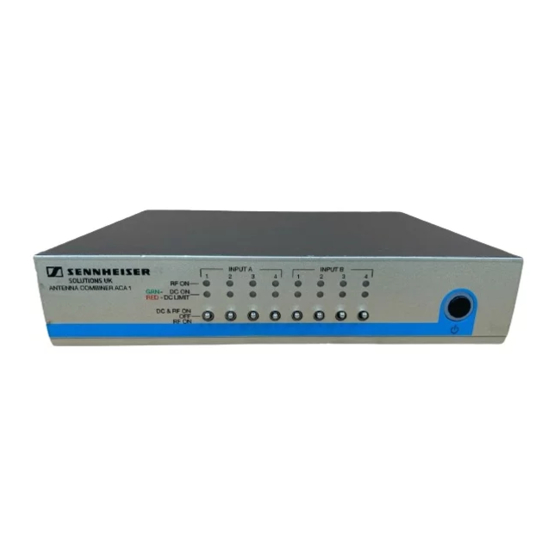
Operating controls Operating controls Front side INPUT A INPUT B: two groups of identical switches and LEDs according to the rear side antenna inputs IN A1-IN A4 and IN B1-IN B4: ³ RF ON DC & RF ON switch to select active/passive antennas ·... -
Page 8: Rear Side
NT 3-1 table top power supply CAUTION! Connecting transmitters to the outputs can damage the elec-tronics of the device! The outputs are provided for connecting receivers. Connecting the ACA 1 to transmitters will cause malfunction and could result in permanent damage... -
Page 9: Putting The Aca 1 Into Operation
Putting the ACA 1 into operation Putting the ACA 1 into operation Preparing the ACA 1 for use Place the ACA 1 on a flat, horizontal surface. Please note that the device feet can leave stains on delicate surfaces! Mounting the ACA 1 into a 19” rack... - Page 10 ACA 1. ¾ Secure the rack mount “ears” (supplied with the optional GA 3 rack adapter) to the ACA 1 using the previously removed recessed head screws. µ Secure the blanking plate to one of the rack mount ¾...
- Page 11 Putting the ACA 1 into operation Connecting devices to the ACA 1 Connecting The ACA 1 provides two channels A and B. You can connect up the antennas to 4 antennas per channel (diversity). Each input can supply up to 250 mA for an active antenna.
- Page 12 Putting the ACA 1 into operation Connecting You can connect two receivers or receiver systems (e.g. the receivers receivers combined via ASA 1, ASA 3000) to the ACA 1. Groups of daisy-chainded receivers such as or EM 3732 may also be connected.
-
Page 13: Using The Aca 1
Using the ACA 1 The NT 3-1 table top power supply connection can be tight fitting at first usage. Using the ACA 1 Switching the ACA 1 on button ¿. Briefly press the STANDBY ´ The operation indicator lights up green. - Page 14 ACA 1 are switched off. Disconnecting the ACA 1 from the mains ³ STANDBY button does disconnect the ACA 1 from the mains. To disconnect the ACA 1 from the mains:...
- Page 15 Using the ACA 1 Unplug the NT 3-1 table top power supply from the wall socket. The ACA 1 is switched off.
-
Page 16: Example 1: Studio Complex
50 ohm coaxial cables connect each antenna to a centrally loca- ted ACA 1 combiner which feeds the radio signal from all of the antennas to the radio receivers. Boosters may be required on long cable runs. -
Page 17: Example 2: Large Church
50 ohm coaxial cables connect each antenna to a centrally located ACA 1 combiner which feeds the radio signal from all of the antennas to the radio receivers. Boosters may be required on long cable runs. The ACA 1 provides 12V DC power at each input to power boosters or active antennas as required. -
Page 18: Cleaning The Aca 1
Keep all liquids away from the device. Do not use any solvents or cleansing agents. Before cleaning, disconnect the ACA 1 from the mains (see page 12). Only use a slightly damp cloth to clean the device. -
Page 19: If A Problem Occurs
RF cable If a problem occurs that is not listed in the above table or if the problem cannot be solved with the proposed solutions, please contact your local Sennheiser partner for assistance. -
Page 20: Accessories
Accessories Accessories The following accessories are available from your Sennheiser partner: Cat. No. Accessory/spare part 503877 NT 3-1 UK Plug-in mains unit 13.8 V/3.4 A - UK version Mounting material 503167 GA 3 19“ rack adapter Antennas 502195 A 3700... - Page 21 Accessories Antenna cables (coaxial cable) 002324 GZL 1019-A1 Co-axial cable - 1 m - BNC/BNC 002325 GZL 1019-A5 Co-axial cable - 5 m - BNC/BNC 002326 GZL 1019-A10 Co-axial cable - 10 m - BNC/BNC 505455 GZL 9000-A5 Antenna Cable - 5 m - N-Connectors 505456 GZL 9000-A10 Antenna Cable - 10 m - N-Connectors 505457...
-
Page 22: Specifications
Specifications Specifications Frequency range 470 to 790 MHz Gain 0 dB (±3dB) RF input power max. 10 mW per input Ω RF connectors BNC female, 50 Supply voltage 13.8 V DC (with NT 3-1 table top power supply) Total current consumption max. -
Page 23: Manufacturer Declarations
In compliance with the following requirements • RoHS Directive (2002/95/EU) • WEEE Directive (2002/96/EU) Please dispose of the ACA 1 at the end of its operational lifetime by taking it to your local collection point or recycling center for such equipment. - Page 24 Sennheiser UK Ltd. Pacific House, Third Avenue, Globe Park, Marlow, Buckinghamshire, SL7 1EY, Great Britain Publ. www.sennheiser.co.uk...