
Related Manuals for Nokia RM-484


Summary of Contents for Nokia RM-484
- Page 1 Nokia Customer Care Service Manual RM-484; RM-485; RM-486 (Nokia N86 8MP; L3&4) Mobile Terminal Part No: (Issue 1) COMPANY CONFIDENTIAL Copyright © 2009 Nokia. All rights reserved.
- Page 2 RM-484; RM-485; RM-486 Amendment Record Sheet Amendment Record Sheet Amendment No Date Inserted By Comments Issue 1 05/2009 Page ii COMPANY CONFIDENTIAL Issue 1 Copyright © 2009 Nokia. All rights reserved.
- Page 3 Nokia operates a policy of continuous development. Nokia reserves the right to make changes and improvements to any of the products described in this document without prior notice. Under no circumstances shall Nokia be responsible for any loss of data or income or any special, incidental, consequential or indirect damages howsoever caused.
-
Page 4: Warnings And Cautions
WCDMA networks and cause problems to 3G cellular phone communication in a wide area. • During testing never activate the GSM or WCDMA transmitter without a proper antenna load, otherwise GSM or WCDMA PA may be damaged. Page iv COMPANY CONFIDENTIAL Issue 1 Copyright © 2009 Nokia. All rights reserved. - Page 5 RM-484; RM-485; RM-486 ESD protection ESD protection Nokia requires that service points have sufficient ESD protection (against static electricity) when servicing the phone. Any product of which the covers are removed must be handled with ESD protection. The SIM card can be replaced without ESD protection if the product is otherwise ready for use.
- Page 6 All of the above suggestions apply equally to the product, battery, charger or any accessory. Page vi COMPANY CONFIDENTIAL Issue 1 Copyright © 2009 Nokia. All rights reserved.
- Page 7 Our policy is of continuous development; details of all technical modifications will be included with service bulletins. While every endeavour has been made to ensure the accuracy of this document, some errors may exist. If any errors are found by the reader, NOKIA MOBILE PHONES Business Group should be notified in writing/e- mail. Please state: •...
-
Page 8: Battery Information
Batteries' performance is particularly limited in temperatures well below freezing. Do not dispose of batteries in a fire! Dispose of batteries according to local regulations (e.g. recycling). Do not dispose as household waste. Page viii COMPANY CONFIDENTIAL Issue 1 Copyright © 2009 Nokia. All rights reserved. - Page 9 RM-484; RM-485; RM-486 Nokia N86 8MP; L3&4 Service Manual Structure Nokia N86 8MP; L3&4 Service Manual Structure 1 General Information 2 Service Tools and Service Concepts 3 BB Troubleshooting 4 RF Troubleshooting 5 Camera Module Troubleshooting 6 FMTx 2.1 Technical Description 7 FMTx 2.1 Troubleshooting...
- Page 10 RM-484; RM-485; RM-486 Nokia N86 8MP; L3&4 Service Manual Structure (This page left intentionally blank.) Page x COMPANY CONFIDENTIAL Issue 1 Copyright © 2009 Nokia. All rights reserved.
- Page 11 Nokia Customer Care 1 — General Information Issue 1 COMPANY CONFIDENTIAL Page 1 –1 Copyright © 2009 Nokia. All rights reserved.
- Page 12 RM-484; RM-485; RM-486 General Information (This page left intentionally blank.) Page 1 –2 COMPANY CONFIDENTIAL Issue 1 Copyright © 2009 Nokia. All rights reserved.
-
Page 13: Table Of Contents
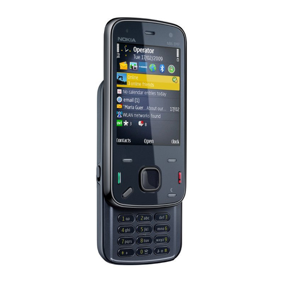
Table 1 Audio ................................1–9 Table 2 Car................................1–9 Table 3 Data ................................1–9 Table 4 Messaging ............................... 1–10 Table 5 Power ..............................1–10 List of Figures Figure 1 View of RM-484............................1–5 Issue 1 COMPANY CONFIDENTIAL Page 1 –3 Copyright © 2009 Nokia. All rights reserved. - Page 14 RM-484; RM-485; RM-486 General Information (This page left intentionally blank.) Page 1 –4 COMPANY CONFIDENTIAL Issue 1 Copyright © 2009 Nokia. All rights reserved.
-
Page 15: Product Selection
General Information Product selection RM-484 is a quad-band handportable multimedia computer, supporting EGSM850/900/1800/1900, with WCDMA VIII (900)/ II (1900)/ I (2100) HSDPA and WLAN. RM-485 supports EGSM850/900/1800/1900, with WCDMA V (850)/ II (1900)/ I (2100) HSDPA and WLAN. RM-486 supports EGSM850/900/1800/1900 and WCDMA V (850)/ II (1900)/ I (2100) HSDPA, but does not support WLAN. -
Page 16: Product Features And Sales Package
• Scene: auto, sports, portrait, close-up, landscape, night, panorama, user defined • Colour tone: normal, sepia, B&W, vivid, negative • Zoom (digital): up to 20x Other camera features: Page 1 –6 COMPANY CONFIDENTIAL Issue 1 Copyright © 2009 Nokia. All rights reserved. - Page 17 • Nokia XpressPrint – direct printing via USB (PictBridge), Bluetooth (BPP), and WLAN (UPnP), from memory card or via online printing Store • Nokia XpressTransfer – easy to transfer and organize photos and video between your device and a compatible PC • Nokia Lifeblog (mobile & PC) Music •...
- Page 18 • MicroSDHC memory card - support up to 16GB (hot swappable) • Nokia 3.5 mm AV connector Add-on software framework • Symbian 9.3 OS • Nokia Series 60, 3rd edition, feature pack 3 • Java: MIDP2.0 • C++ and Java SDKs Additional technical specifications •...
-
Page 19: Mobile Enhancements
RM-484; RM-485; RM-486 General Information • Nokia Music Headset AD-54/HS-83 (Black/Silver) or AD-54/HS-44 (White/Silver) • Connectivity cable (CA-101) Mobile enhancements Table 1 Audio Enhancement Type Music headset HS-44 with AD-54 3.5mm stereo plug Basic headset HS-41 Stereo headset WH-800 Bluetooth headset... -
Page 20: Technical Specifications
GSM1800: 1805 - 1880 MHz GSM1900: 1930 - 1990 MHz WCDMA VIII (900): 925- 960 MHz WCDMA II (1900): 1930-1990MHz WCDMA I (2100): 2110 - 2170 MHz Page 1 –10 COMPANY CONFIDENTIAL Issue 1 Copyright © 2009 Nokia. All rights reserved. - Page 21 200 kHz (WCDMA II 100/200 kHz) Number of Tx power levels GSM850: 15 GSM900: 15 GSM1800: 16 GSM1900: 16 WCDMA VIII (900): 75 WCDMA II (1900): 75 WCDMA I (2100): 75 Issue 1 COMPANY CONFIDENTIAL Page 1 –11 Copyright © 2009 Nokia. All rights reserved.
-
Page 22: Main Rf Characteristics For Gsm850/900/1800/1900 And Wcdma V/Ii/I Phones
EDGE output power EDGE850: +5 … +29dBm/3.2mW … 794mW EDGE900: +5 … +29dBm/3.2mW … 794mW EDGE1800: +0 … +26dBm/1.0mW … 400mW EDGE1900:+0 … +26dBm/1.0mW … 400mW Page 1 –12 COMPANY CONFIDENTIAL Issue 1 Copyright © 2009 Nokia. All rights reserved. -
Page 23: Battery Endurance
No operation or No storage. An attempt to operate <-40 C and >+85 storage may cause permanent damage Charging allowed C ... +55 Issue 1 COMPANY CONFIDENTIAL Page 1 –13 Copyright © 2009 Nokia. All rights reserved. - Page 24 Condensed or dripping water may cause intermittent malfunctions. Protection against dripping water has to be implemented in (enclosure) mechanics. Continuous dampness will cause permanent damage to the module. Page 1 –14 COMPANY CONFIDENTIAL Issue 1 Copyright © 2009 Nokia. All rights reserved.
-
Page 25: Issue 1 Company Confidential Page
Nokia Customer Care 2 — Service Tools and Service Concepts Issue 1 COMPANY CONFIDENTIAL Page 2 –1 Copyright © 2009 Nokia. All rights reserved. - Page 26 RM-484; RM-485; RM-486 Service Tools and Service Concepts (This page left intentionally blank.) Page 2 –2 COMPANY CONFIDENTIAL Issue 1 Copyright © 2009 Nokia. All rights reserved.
-
Page 27: Table Of Contents
Figure 11 Module jig service concept with SB-6....................2–18 Figure 12 RF testing concept with RF coupler ....................2–19 Figure 13 Service concept for RF testing and RF/BB tuning ................2–20 Issue 1 COMPANY CONFIDENTIAL Page 2 –3 Copyright © 2009 Nokia. All rights reserved. - Page 28 RM-484; RM-485; RM-486 Service Tools and Service Concepts (This page left intentionally blank.) Page 2 –4 COMPANY CONFIDENTIAL Issue 1 Copyright © 2009 Nokia. All rights reserved.
-
Page 29: Service Tools
The table below gives a short overview of service devices that can be used for testing, error analysis, and repair of product RM-484; RM-485; RM-486. For the correct use of the service devices, and the best effort of workbench setup, please refer to various concepts. -
Page 30: Cables
The table below gives a short overview of service devices that can be used for testing, error analysis, and repair of product RM-484; RM-485; RM-486. For the correct use of the service devices, and the best effort of workbench setup, please refer to various concepts. -
Page 31: Ca-101
CA-35S is a power cable for connecting, for example, the FPS-21 flash prommer to the Point-Of-Sales (POS) flash adapter. CA-56RS RF cable Small RF cable that is used for RF tuning with product specific module jig. Issue 1 COMPANY CONFIDENTIAL Page 2 –7 Copyright © 2009 Nokia. All rights reserved. -
Page 32: Pcs-1
XCS-4 Modular cable XCS-4 is a shielded (one specially shielded conductor) modular cable for flashing and service purposes. Page 2 –8 COMPANY CONFIDENTIAL Issue 1 Copyright © 2009 Nokia. All rights reserved. -
Page 33: Service Concepts
Figure 2 POS flash concept Type Description Product specific tools BL-5K Battery Other tools FLS-5 POS flash dongle PC with Phoenix service software Cables CA-101 USB connectivity cable Issue 1 COMPANY CONFIDENTIAL Page 2 –9 Copyright © 2009 Nokia. All rights reserved. -
Page 34: Flash Concept With Fps-10
Other devices FPS-10 Flash prommer box PKD-1/PK-1 SW security device SS-46 Interface adapter PC with Phoenix service software Cables XCS-4 Modular cable CA-35S Power cable USB cable Page 2 –10 COMPANY CONFIDENTIAL Issue 1 Copyright © 2009 Nokia. All rights reserved. -
Page 35: Flash Concept With Fps-10
SW security device SS-62 Flash adapter base SX-4 Smart card PC with Phoenix service software Cables PCS-1 Power cable XCS-4 Modular cable Standard USB cable USB cable Issue 1 COMPANY CONFIDENTIAL Page 2 –11 Copyright © 2009 Nokia. All rights reserved. -
Page 36: Flash Concept With Fps-10 And Sb-6............................................................................................................. Flash Concept With Ss-46 And Ca-89Ds
Flash prommer box PKD-1/PK-1 SW security device SS-46 Interface adapter SB-6 Bluetooth test and interface box PC with Phoenix service software Cables XCS-4 Modular cable CA-35S Power cable Page 2 –12 COMPANY CONFIDENTIAL Issue 1 Copyright © 2009 Nokia. All rights reserved. - Page 37 Figure 6 Flash concept with SS-46 and CA-89DS Type Description Product specific tools FS-113 Flash adapter Other tools FLS-5 Flash device SS-46 Interface adapter PC with Phoenix service software Cables CA-89DS Cable Issue 1 COMPANY CONFIDENTIAL Page 2 –13 Copyright © 2009 Nokia. All rights reserved.
-
Page 38: Flash Concept With Ss-62 And Ca-89Ds
Flash adapter Other tools CU-4 Control unit FLS-5 Flash device SS-62 Flash adapter base PC with Phoenix service software Cables CA-89DS Cable PCS-1 Power cable USB cable Page 2 –14 COMPANY CONFIDENTIAL Issue 1 Copyright © 2009 Nokia. All rights reserved. -
Page 39: Flash Concept With Fps-10, Ss-62 And
SW security device SS-62 Flash adapter base SB-6 Bluetooth test and interface box SX-4 Smart card PC with Phoenix service software Cables XCS-4 Modular cable PCS-1 Power cable Issue 1 COMPANY CONFIDENTIAL Page 2 –15 Copyright © 2009 Nokia. All rights reserved. -
Page 40: Flash Concept With Fps-10, Ss-62 And
SW security device SB-7 WLAN test box SS-62 Flash adapter base SX-4 Smart card PC with Phoenix service software Cables XCS-4 Modular cable PCS-1 Power cable Page 2 –16 COMPANY CONFIDENTIAL Issue 1 Copyright © 2009 Nokia. All rights reserved. -
Page 41: Module Jig Service Concept
Flash prommer box PK-1 SW security device SX-4 Smart card PC with VPOS and Phoenix service software Measurement equipment Cables PCS-1 DC power cable XCS-4 Modular cable Issue 1 COMPANY CONFIDENTIAL Page 2 –17 Copyright © 2009 Nokia. All rights reserved. -
Page 42: Module Jig Service Concept With
Module jig service concept with SB-6 Figure 11 Module jig service concept with SB-6 Type Description Product specific tools MJ-208 Module jig Other tools CU-4 Control unit FPS-10 Flash prommer box Page 2 –18 COMPANY CONFIDENTIAL Issue 1 Copyright © 2009 Nokia. All rights reserved. -
Page 43: Rf Testing Concept With Rf Coupler
GPIB control cable USB cable RF testing concept with RF coupler Figure 12 RF testing concept with RF coupler Type Description Product specific devices FS-113 Flash adapter Issue 1 COMPANY CONFIDENTIAL Page 2 –19 Copyright © 2009 Nokia. All rights reserved. -
Page 44: Service Concept For Rf Testing And Rf/Bb Tuning
CA-56RS RF cable GPIB control cable USB cable Service concept for RF testing and RF/BB tuning Figure 13 Service concept for RF testing and RF/BB tuning Page 2 –20 COMPANY CONFIDENTIAL Issue 1 Copyright © 2009 Nokia. All rights reserved. - Page 45 Smart card reader PC with Phoenix service software Cables DAU-9S MBUS cable PCS-1 DC power cable CA-56RS RF cable CA-56RS RF tuning cable GPIB control cable USB cable Issue 1 COMPANY CONFIDENTIAL Page 2 –21 Copyright © 2009 Nokia. All rights reserved.
- Page 46 RM-484; RM-485; RM-486 Service Tools and Service Concepts (This page left intentionally blank.) Page 2 –22 COMPANY CONFIDENTIAL Issue 1 Copyright © 2009 Nokia. All rights reserved.
-
Page 47: Issue 1 Company Confidential Page
Nokia Customer Care 3 — BB Troubleshooting Issue 1 COMPANY CONFIDENTIAL Page 3 –1 Copyright © 2009 Nokia. All rights reserved. - Page 48 RM-484; RM-485; RM-486 BB Troubleshooting (This page left intentionally blank.) Page 3 –2 COMPANY CONFIDENTIAL Issue 1 Copyright © 2009 Nokia. All rights reserved.
-
Page 49: Table 5 Power
Troubleshooting............................3–59 GPS layout and basic test points........................3–59 GPS Settings for Phoenix ..........................3–60 control..............................3–60 Quick Test window............................ 3–61 GPS failure troubleshooting .......................... 3–63 Issue 1 COMPANY CONFIDENTIAL Page 3 –3 Copyright © 2009 Nokia. All rights reserved. - Page 50 Figure 24 GPS Quick Test window ........................3–62 Figure 25 WLAN circuitry ............................ 3–64 Figure 26 WLAN auto tune settings........................3–69 Figure 27 WLAN auto tune results ........................3–70 Page 3 –4 COMPANY CONFIDENTIAL Issue 1 Copyright © 2009 Nokia. All rights reserved.
-
Page 51: Baseband Main Troubleshooting
RM-484; RM-485; RM-486 BB Troubleshooting Baseband main troubleshooting Troubleshooting flow Issue 1 COMPANY CONFIDENTIAL Page 3 –5 Copyright © 2009 Nokia. All rights reserved. - Page 52 RM-484; RM-485; RM-486 BB Troubleshooting Page 3 –6 COMPANY CONFIDENTIAL Issue 1 Copyright © 2009 Nokia. All rights reserved.
-
Page 53: General Power Checking
V_ELVSS TPS65136 -4.9 Falcon OLED Display VCORE_WD LP5952 White Dwarf Core VBAT VCORE BETTY Not used VDRAM_V AVILMA 1.82 Not used VLED BETTY 6-18 Not used Issue 1 COMPANY CONFIDENTIAL Page 3 –7 Copyright © 2009 Nokia. All rights reserved. -
Page 54: Backup Battery Troubleshooting
Switch off the phone, disconnect the main battery and monitor that the voltage of the backup battery decreases. Normal behaviour of the voltage is described in the figures below: Page 3 –8 COMPANY CONFIDENTIAL Issue 1 Copyright © 2009 Nokia. All rights reserved. - Page 55 G2200 if necessary. If the voltage stays ~0V, check resistance VBACK against GND. If there is no shortcircuit, AVILMA N2200 is faulty. Replace N2200. Issue 1 COMPANY CONFIDENTIAL Page 3 –9 Copyright © 2009 Nokia. All rights reserved.
-
Page 56: Dead Or Jammed Device Troubleshooting
RM-484; RM-485; RM-486 BB Troubleshooting Dead or jammed device troubleshooting Troubleshooting flow Page 3 –10 COMPANY CONFIDENTIAL Issue 1 Copyright © 2009 Nokia. All rights reserved. -
Page 57: Keyboard Troubleshooting
(shortcut or open connection). For a more detailed description of the keyboard and keymatrix, see section Keyboard. Phoenix . If the failure mode is not clear, start with the Keyboard Test in Issue 1 COMPANY CONFIDENTIAL Page 3 –11 Copyright © 2009 Nokia. All rights reserved. - Page 58 RM-484; RM-485; RM-486 BB Troubleshooting Troubleshooting flow Page 3 –12 COMPANY CONFIDENTIAL Issue 1 Copyright © 2009 Nokia. All rights reserved.
-
Page 59: Hall Sensor Troubleshooting
RM-484; RM-485; RM-486 BB Troubleshooting Hall sensor troubleshooting Troubleshooting flow Issue 1 COMPANY CONFIDENTIAL Page 3 –13 Copyright © 2009 Nokia. All rights reserved. -
Page 60: Tv- Out Troubleshooting
RM-484; RM-485; RM-486 BB Troubleshooting TV- out troubleshooting Troubleshooting flow Page 3 –14 COMPANY CONFIDENTIAL Issue 1 Copyright © 2009 Nokia. All rights reserved. -
Page 61: General Power Checking Troubleshooting
RM-484; RM-485; RM-486 BB Troubleshooting General power checking troubleshooting Troubleshooting flow Issue 1 COMPANY CONFIDENTIAL Page 3 –15 Copyright © 2009 Nokia. All rights reserved. -
Page 62: Usb Troubleshooting
RM-484; RM-485; RM-486 BB Troubleshooting USB troubleshooting Troubleshooting flow Page 3 –16 COMPANY CONFIDENTIAL Issue 1 Copyright © 2009 Nokia. All rights reserved. -
Page 63: Sim Card Troubleshooting
RM-484; RM-485; RM-486 BB Troubleshooting SIM card troubleshooting Troubleshooting flow Issue 1 COMPANY CONFIDENTIAL Page 3 –17 Copyright © 2009 Nokia. All rights reserved. -
Page 64: Microsd Card Troubleshooting
RM-484; RM-485; RM-486 BB Troubleshooting MicroSD card troubleshooting Troubleshooting flow Page 3 –18 COMPANY CONFIDENTIAL Issue 1 Copyright © 2009 Nokia. All rights reserved. - Page 65 RM-484; RM-485; RM-486 BB Troubleshooting Issue 1 COMPANY CONFIDENTIAL Page 3 –19 Copyright © 2009 Nokia. All rights reserved.
-
Page 66: Combo Memory Troubleshooting
RM-484; RM-485; RM-486 BB Troubleshooting Combo memory troubleshooting Troubleshooting flow Page 3 –20 COMPANY CONFIDENTIAL Issue 1 Copyright © 2009 Nokia. All rights reserved. -
Page 67: Flash Programming Troubleshooting
RM-484; RM-485; RM-486 BB Troubleshooting Flash programming troubleshooting Troubleshooting flow Issue 1 COMPANY CONFIDENTIAL Page 3 –21 Copyright © 2009 Nokia. All rights reserved. - Page 68 RM-484; RM-485; RM-486 BB Troubleshooting Page 3 –22 COMPANY CONFIDENTIAL Issue 1 Copyright © 2009 Nokia. All rights reserved.
- Page 69 RM-484; RM-485; RM-486 BB Troubleshooting Issue 1 COMPANY CONFIDENTIAL Page 3 –23 Copyright © 2009 Nokia. All rights reserved.
-
Page 70: Usb Charging Troubleshooting
RM-484; RM-485; RM-486 BB Troubleshooting USB charging troubleshooting Troubleshooting flow Page 3 –24 COMPANY CONFIDENTIAL Issue 1 Copyright © 2009 Nokia. All rights reserved. -
Page 71: Clocking Troubleshooting
RM-484; RM-485; RM-486 BB Troubleshooting Clocking troubleshooting Troubleshooting flow Issue 1 COMPANY CONFIDENTIAL Page 3 –25 Copyright © 2009 Nokia. All rights reserved. -
Page 72: Power Key Troubleshooting
RM-484; RM-485; RM-486 BB Troubleshooting Power key troubleshooting Troubleshooting flow Page 3 –26 COMPANY CONFIDENTIAL Issue 1 Copyright © 2009 Nokia. All rights reserved. -
Page 73: User Interface Troubleshooting
RM-484; RM-485; RM-486 BB Troubleshooting User interface troubleshooting Troubleshooting flow Issue 1 COMPANY CONFIDENTIAL Page 3 –27 Copyright © 2009 Nokia. All rights reserved. -
Page 74: Accelerometer Troubleshooting
RM-484; RM-485; RM-486 BB Troubleshooting Accelerometer troubleshooting Accelerometer general troubleshooting Page 3 –28 COMPANY CONFIDENTIAL Issue 1 Copyright © 2009 Nokia. All rights reserved. - Page 75 RM-484; RM-485; RM-486 BB Troubleshooting Accelerometer self test troubleshooting Issue 1 COMPANY CONFIDENTIAL Page 3 –29 Copyright © 2009 Nokia. All rights reserved.
-
Page 76: Magnetometer Troubleshooting
• Set the phone and reference compass to the rotating platform • Connect the phone to the PC and start Phoenix Tests • General troubleshooting test • Self-test (ST) • Azimuth check test Page 3 –30 COMPANY CONFIDENTIAL Issue 1 Copyright © 2009 Nokia. All rights reserved. - Page 77 RM-484; RM-485; RM-486 BB Troubleshooting Magnetometer general troubleshooting Issue 1 COMPANY CONFIDENTIAL Page 3 –31 Copyright © 2009 Nokia. All rights reserved.
- Page 78 RM-484; RM-485; RM-486 BB Troubleshooting Magnetometer self test troubleshooting Page 3 –32 COMPANY CONFIDENTIAL Issue 1 Copyright © 2009 Nokia. All rights reserved.
-
Page 79: Display Troubleshooting
Display Troubleshooting Display blank There is no image on the display. Display looks the same as if the phone is off even when the phone is on. Issue 1 COMPANY CONFIDENTIAL Page 3 –33 Copyright © 2009 Nokia. All rights reserved. - Page 80 Image on the display can be corrupted or part of the image can be missing. If part of image is missing change the UI module. If the image is otherwise corrupted, follow the path below. Page 3 –34 COMPANY CONFIDENTIAL Issue 1 Copyright © 2009 Nokia. All rights reserved.
-
Page 81: Illumination Troubleshooting
At first, cover the ALS and check if they are OK. If they are not, go to the troubleshooting diagram below. Issue 1 COMPANY CONFIDENTIAL Page 3 –35 Copyright © 2009 Nokia. All rights reserved. - Page 82 RM-484; RM-485; RM-486 BB Troubleshooting Troubleshooting flow Page 3 –36 COMPANY CONFIDENTIAL Issue 1 Copyright © 2009 Nokia. All rights reserved.
- Page 83 At first, cover the ALS and check if they are OK. If they are not, go to the troubleshooting diagram below. Issue 1 COMPANY CONFIDENTIAL Page 3 –37 Copyright © 2009 Nokia. All rights reserved.
-
Page 84: Led Driver Troubleshooting
RM-484; RM-485; RM-486 BB Troubleshooting LED driver troubleshooting Troubleshooting flow Page 3 –38 COMPANY CONFIDENTIAL Issue 1 Copyright © 2009 Nokia. All rights reserved. -
Page 85: I/O Expander Troubleshooting
The input signal for each loop test can be either single-ended or differential. Exception to this is a digital microphone, which needs input signal from an external sound source (laptop speaker) to playback eg. 1kHz sine wave from 5cm distance Issue 1 COMPANY CONFIDENTIAL Page 3 –39 Copyright © 2009 Nokia. All rights reserved. -
Page 86: Test Procedure
External HS_MIC & EarP & 1000 Mic to Internal EarN & Earpiece External HS_MIC & J2103 & 1000 Mic to J2104 Internal J2101 & handsfre J2102 Page 3 –40 COMPANY CONFIDENTIAL Issue 1 Copyright © 2009 Nokia. All rights reserved. - Page 87 Figure 15 Single-ended output waveform of the Ext_in_IHF_out out loop measurement when speaker is connected (measured at speaker pads), no filter is used External output from AV Issue 1 COMPANY CONFIDENTIAL Page 3 –41 Copyright © 2009 Nokia. All rights reserved.
- Page 88 BB Troubleshooting Figure 16 Single-ended output waveform of the Ext_in_Ext_out loop External output from AV (acoustic input) Figure 17 Single-ended output waveform of the Digital_stereo_microphone_in_Ext_out loop Page 3 –42 COMPANY CONFIDENTIAL Issue 1 Copyright © 2009 Nokia. All rights reserved.
-
Page 89: External Earpiece Troubleshooting
RM-484; RM-485; RM-486 BB Troubleshooting External earpiece troubleshooting Troubleshooting flow Issue 1 COMPANY CONFIDENTIAL Page 3 –43 Copyright © 2009 Nokia. All rights reserved. -
Page 90: Dac33 Troubleshooting
RM-484; RM-485; RM-486 BB Troubleshooting DAC33 troubleshooting Troubleshooting flow Page 3 –44 COMPANY CONFIDENTIAL Issue 1 Copyright © 2009 Nokia. All rights reserved. -
Page 91: External Microphone Troubleshooting
RM-484; RM-485; RM-486 BB Troubleshooting External microphone troubleshooting Troubleshooting flow Issue 1 COMPANY CONFIDENTIAL Page 3 –45 Copyright © 2009 Nokia. All rights reserved. -
Page 92: Internal Earpiece Troubleshooting
RM-484; RM-485; RM-486 BB Troubleshooting Internal earpiece troubleshooting Troubleshooting flow Page 3 –46 COMPANY CONFIDENTIAL Issue 1 Copyright © 2009 Nokia. All rights reserved. -
Page 93: Internal Handsfree Speaker Troubleshooting
RM-484; RM-485; RM-486 BB Troubleshooting Internal handsfree speaker troubleshooting Troubleshooting flow Issue 1 COMPANY CONFIDENTIAL Page 3 –47 Copyright © 2009 Nokia. All rights reserved. -
Page 94: Internal Microphone Troubleshooting
RM-484; RM-485; RM-486 BB Troubleshooting Internal microphone troubleshooting Troubleshooting flow Page 3 –48 COMPANY CONFIDENTIAL Issue 1 Copyright © 2009 Nokia. All rights reserved. -
Page 95: Vibra Troubleshooting
RM-484; RM-485; RM-486 BB Troubleshooting Vibra troubleshooting Troubleshooting flow Issue 1 COMPANY CONFIDENTIAL Page 3 –49 Copyright © 2009 Nokia. All rights reserved. -
Page 96: Als Technical Description And Troubleshooting
5. Open the Lights tab, check Ambient Light Sensor check box, click Read, cover the sensor and click Read again. When covered, Luminance reading should be less than after clicking Read without covering the sensor. Page 3 –50 COMPANY CONFIDENTIAL Issue 1 Copyright © 2009 Nokia. All rights reserved. -
Page 97: Re-Tuning Als
Connect reference phone to Phoenix and set the phone (e.g. on the table) so that the amount of ambient light seen by ALS is as stable as possible. Start Phoenix. Choose File→Scan Product. Issue 1 COMPANY CONFIDENTIAL Page 3 –51 Copyright © 2009 Nokia. All rights reserved. -
Page 98: Bluetooth And Fm Radio Troubleshooting
Introduction to Bluetooth/FM radio troubleshooting Bluetooth/WLAN antenna The BT RF signal is routed from BTFMRDS2.3M through the WLAN module to the shared WLAN/BT antenna in the phone's C-cover. Page 3 –52 COMPANY CONFIDENTIAL Issue 1 Copyright © 2009 Nokia. All rights reserved. - Page 99 Bluetooth on phone user detached component in FM connection or FM circuit interface, but unable to detect antenna circuit component local FM radio stations with Nokia headset inserted Issue 1 COMPANY CONFIDENTIAL Page 3 –53 Copyright © 2009 Nokia. All rights reserved.
- Page 100 The self tests run from Phoenix software are used for fault diagnosis. If Phoenix software is not available the functional tests with phone accessories are sufficient to verify the functionality Bluetooth and FM radio receiver and transmitter. Page 3 –54 COMPANY CONFIDENTIAL Issue 1 Copyright © 2009 Nokia. All rights reserved.
-
Page 101: Bluetooth Ber Test
Bluetooth and FM radio self tests in Phoenix Prerequisites A flash adapter (or phone data cable) connected to a PC with Phoenix service software is required. Issue 1 COMPANY CONFIDENTIAL Page 3 –55 Copyright © 2009 Nokia. All rights reserved. - Page 102 6. In the • ST_LPRF_IF_TEST • ST_LPRF_AUDIO_LINES_TEST • ST_BT_WAKEUP_TEST • ST_RADIO_TEST 7. To run the tests, click Start. Phoenix Figure 21 Bluetooth and FM radio self tests in Page 3 –56 COMPANY CONFIDENTIAL Issue 1 Copyright © 2009 Nokia. All rights reserved.
-
Page 103: Bluetooth Troubleshooting
RM-484; RM-485; RM-486 BB Troubleshooting Bluetooth troubleshooting Troubleshooting flow Issue 1 COMPANY CONFIDENTIAL Page 3 –57 Copyright © 2009 Nokia. All rights reserved. -
Page 104: Fm Radio Troubleshooting
RM-484; RM-485; RM-486 BB Troubleshooting FM radio troubleshooting Troubleshooting flow Page 3 –58 COMPANY CONFIDENTIAL Issue 1 Copyright © 2009 Nokia. All rights reserved. -
Page 105: Fm Radio Testing
The GPS components are located on small 2nd PWB. Satellite signals are picked up by the phones GPS antenna in the C-cover. The signal is then routed through a filter before being processed by the GPS5350 receiver ASIC. Verify that the GPS voltage and clock signal levels are as in RM-484 GPS schematics. Issue 1 COMPANY CONFIDENTIAL Page 3 –59... -
Page 106: Gps Settings For Phoenix
(approx -45dBm) because it is a leakage connection. Context Use the following to test GPS using Phoenix. Steps 1. Place phone to Flash Adaptor. 2. Start Phoenix service software. Page 3 –60 COMPANY CONFIDENTIAL Issue 1 Copyright © 2009 Nokia. All rights reserved. -
Page 107: Quick Test Window
Signal Generator should be adjusted so a reading of SNR 40 dB is achieved with the reference unit. A good starting point is to set up the signal generator to -45dBm. These checks are part of GPS failure troubleshooting (page 3–63). Issue 1 COMPANY CONFIDENTIAL Page 3 –61 Copyright © 2009 Nokia. All rights reserved. - Page 108 RM-484; RM-485; RM-486 BB Troubleshooting Figure 24 GPS Quick Test window Page 3 –62 COMPANY CONFIDENTIAL Issue 1 Copyright © 2009 Nokia. All rights reserved.
- Page 109 BT device. The WLAN SW is downloaded from the host engine when the WLAN is turned on over the dedicated SPI interface. BT and WLAN have their own 38,4MHz TCXO. Issue 1 COMPANY CONFIDENTIAL Page 3 –63 Copyright © 2009 Nokia. All rights reserved.
- Page 110 WLAN acknowledges the data blocks and so the self test is a good way to confirm that the WLAN module is communicating with the Host. The result column will change to Passed after a few seconds if operating properly. Page 3 –64 COMPANY CONFIDENTIAL Issue 1 Copyright © 2009 Nokia. All rights reserved.
- Page 111 This test verifies that the WLAN to BTH co-existence interface signals are properly connected and there are no open circuit or shorts on the four interface signals. The co-existence interface comprises BTH Txconfig, BTH RF Active, BTH Priority, and BTH Frequency. Issue 1 COMPANY CONFIDENTIAL Page 3 –65 Copyright © 2009 Nokia. All rights reserved.
- Page 112 1 Monitor the WLAN TX spectrum on a Spectrum analyser. (When making a radiated test ensure that other WLAN devices are not transmitting as these may be detected as well, confusing the result). A typical 11MBPS TX spectrum is shown in figure below. Page 3 –66 COMPANY CONFIDENTIAL Issue 1 Copyright © 2009 Nokia. All rights reserved.
- Page 113 11MBPS, 802.11b mode of operation. RX Tests Prerequisites Connect complete phone assembly with C-cover to a PC with Phoenix service software using a USB data cable. Issue 1 COMPANY CONFIDENTIAL Page 3 –67 Copyright © 2009 Nokia. All rights reserved.
- Page 114 RF cable. Start Phoenix WLAN autotune window. Check the settings and verify your PC communicates with CMU200 via GPIB. Auto tuning procedure 1 Start tuning by pressing Tune. Page 3 –68 COMPANY CONFIDENTIAL Issue 1 Copyright © 2009 Nokia. All rights reserved.
- Page 115 RM-484; RM-485; RM-486 BB Troubleshooting Figure 26 WLAN auto tune settings Issue 1 COMPANY CONFIDENTIAL Page 3 –69 Copyright © 2009 Nokia. All rights reserved.
- Page 116 RM-484; RM-485; RM-486 BB Troubleshooting Figure 27 WLAN auto tune results Page 3 –70 COMPANY CONFIDENTIAL Issue 1 Copyright © 2009 Nokia. All rights reserved.
- Page 117 Nokia Customer Care 4 — RF Troubleshooting Issue 1 COMPANY CONFIDENTIAL Page 4 –1 Copyright © 2009 Nokia. All rights reserved.
- Page 118 RM-484; RM-485; RM-486 RF Troubleshooting (This page left intentionally blank.) Page 4 –2 COMPANY CONFIDENTIAL Issue 1 Copyright © 2009 Nokia. All rights reserved.
- Page 119 Figure 33 Phoenix WCDMA RX power measurement window ................ 4–12 Figure 34 Phoenix GSM RF controls window..................... 4–14 Figure 35 Antenna contacts and matching components ................4–18 Issue 1 COMPANY CONFIDENTIAL Page 4 –3 Copyright © 2009 Nokia. All rights reserved.
- Page 120 RM-484; RM-485; RM-486 RF Troubleshooting (This page left intentionally blank.) Page 4 –4 COMPANY CONFIDENTIAL Issue 1 Copyright © 2009 Nokia. All rights reserved.
-
Page 121: General Rf Troubleshooting
RF shielded environment, testing at frequencies of nearby base stations should be avoided. Level of repair The scope of this guideline is to verify functionality of the cellular RF block without removing RF shield. Issue 1 COMPANY CONFIDENTIAL Page 4 –5 Copyright © 2009 Nokia. All rights reserved. -
Page 122: Rf Key Components And Test Points
RM-484; RM-485; RM-486 RF Troubleshooting RF key components and test points Figure 28 RF key components Figure 29 RF test points Page 4 –6 COMPANY CONFIDENTIAL Issue 1 Copyright © 2009 Nokia. All rights reserved. -
Page 123: Auto Tuning
Self tests are recommended to be made when phone is in jig and 50 Ohm load is connected to RF connector. Otherwise powertests may fail depending on antenna load. Issue 1 COMPANY CONFIDENTIAL Page 4 –7 Copyright © 2009 Nokia. All rights reserved. - Page 124 RM-484; RM-485; RM-486 RF Troubleshooting Page 4 –8 COMPANY CONFIDENTIAL Issue 1 Copyright © 2009 Nokia. All rights reserved.
-
Page 125: Receiver Troubleshooting
The reading should reflect the level of the signal generator (-losses) +/- 5 dB. When varying the level in the range -30 to -102 dBm the reading should then follow within +/-5 dB. Issue 1 COMPANY CONFIDENTIAL Page 4 –9 Copyright © 2009 Nokia. All rights reserved. -
Page 126: Gsm Receiver Troubleshooting Flowchart
WCDMA RX chain activation for manual measurement Steps 1. Via Phoenix Testing menu, choose WCDMA/RX Control. 2. In the RX control window, make the following settings: Page 4 –10 COMPANY CONFIDENTIAL Issue 1 Copyright © 2009 Nokia. All rights reserved. -
Page 127: Wcdma Rssi Measurement
Connect signal generator to RF connector and use appropriate frequency for each channel (2141MHz for channel 10700 WCDMA band I, WCDMA modulation). Steps 1. Set the following RF generator settings: Issue 1 COMPANY CONFIDENTIAL Page 4 –11 Copyright © 2009 Nokia. All rights reserved. - Page 128 Figure 33 Phoenix WCDMA RX power measurement window 4. Click Start to perform the measurement. Note: WCDMA RSSI measurement is accurate only with WCDMA modulated signal. Page 4 –12 COMPANY CONFIDENTIAL Issue 1 Copyright © 2009 Nokia. All rights reserved.
-
Page 129: Wcdma Receiver Troubleshooting Flowchart
50 Ω load to the RF connector (antenna, RF-measurement equipment or at least a 2 W dummy load); otherwise the GSM or WCDMA Power amplifier (PA) may be damaged. GSM transmitter troubleshooting Steps 1. Set the phone to local mode. Issue 1 COMPANY CONFIDENTIAL Page 4 –13 Copyright © 2009 Nokia. All rights reserved. - Page 130 Figure 34 Phoenix GSM RF controls window 3. Check the basic TX parameters (i.e. power, phase error, modulation and switching spectrum), using a communication analyser (for example CMU200). Page 4 –14 COMPANY CONFIDENTIAL Issue 1 Copyright © 2009 Nokia. All rights reserved.
- Page 131 RM-484; RM-485; RM-486 RF Troubleshooting 4. Change power level (RF controls) and make sure the power reading follows accordingly. Issue 1 COMPANY CONFIDENTIAL Page 4 –15 Copyright © 2009 Nokia. All rights reserved.
-
Page 132: Wcdma Transmitter Troubleshooting
If settings are changed (eg. new channel), you have to click RF Stop and Send again. 5. Check the basic TX parameters using a communication analyzer (for example CMU200). Page 4 –16 COMPANY CONFIDENTIAL Issue 1 Copyright © 2009 Nokia. All rights reserved. -
Page 133: Antenna Troubleshooting
Antenna contacts, visual check In the main antenna there are two feeds. Check that the feed pads take proper contact to the C-clips on the main PWB. Issue 1 COMPANY CONFIDENTIAL Page 4 –17 Copyright © 2009 Nokia. All rights reserved. - Page 134 There are four matching components C7550, C7551, C7552 and L7550 on the main PWB. Check visually that all components are properly soldered. Figure 35 Antenna contacts and matching components Page 4 –18 COMPANY CONFIDENTIAL Issue 1 Copyright © 2009 Nokia. All rights reserved.
- Page 135 Nokia Customer Care 5 — Camera Module Troubleshooting Issue 1 COMPANY CONFIDENTIAL Page 5 –1 Copyright © 2009 Nokia. All rights reserved.
- Page 136 RM-484; RM-485; RM-486 Camera Module Troubleshooting (This page left intentionally blank.) Page 5 –2 COMPANY CONFIDENTIAL Issue 1 Copyright © 2009 Nokia. All rights reserved.
- Page 137 5–13 Figure 49 Enlargement of a hot pixel........................ 5–14 Figure 50 Light from the flash has reflected on particles in front of the camera ........5–14 Issue 1 COMPANY CONFIDENTIAL Page 5 –3 Copyright © 2009 Nokia. All rights reserved.
- Page 138 RM-484; RM-485; RM-486 Camera Module Troubleshooting (This page left intentionally blank.) Page 5 –4 COMPANY CONFIDENTIAL Issue 1 Copyright © 2009 Nokia. All rights reserved.
-
Page 139: Introduction To Camera Module Troubleshooting
Camera module's sensitivity to light. In equivalent illumination conditions, a less sensitive camera needs a longer exposure time to gather enough light in forming a good image. Analogous to ISO speed in photographic film. Issue 1 COMPANY CONFIDENTIAL Page 5 –5 Copyright © 2009 Nokia. All rights reserved. -
Page 140: The Effect Of Image Taking Conditions On Image Quality
See the figure below for an example. This is normal; do not change the camera module. Page 5 –6 COMPANY CONFIDENTIAL Issue 1 Copyright © 2009 Nokia. All rights reserved. -
Page 141: Phone Display
In practice, this means that when taking an image indoors and having, for example, a window behind the object, the result is usually poor. This is normal behaviour; do not change the camera module. Issue 1 COMPANY CONFIDENTIAL Page 5 –7 Copyright © 2009 Nokia. All rights reserved. - Page 142 Generally this kind of reflections are common in all optical systems. This is normal behaviour; do not change the camera module. Page 5 –8 COMPANY CONFIDENTIAL Issue 1 Copyright © 2009 Nokia. All rights reserved.
- Page 143 Figure 41 A lens reflection effect caused by sunshine Examples of good quality images Figure 42 Good image taken indoors Figure 43 Good image taken outdoors Issue 1 COMPANY CONFIDENTIAL Page 5 –9 Copyright © 2009 Nokia. All rights reserved.
-
Page 144: Image Quality Analysis
However, it is possible that a larger particle disturbs the user, causing need for service. Figure 44 Effects of dust on optical path Page 5 –10 COMPANY CONFIDENTIAL Issue 1 Copyright © 2009 Nokia. All rights reserved. -
Page 145: Testing Camera Image Sharpness
Any particles inside the cavity between the protection window and lens have most probably been trapped there in the assembly phase at a Nokia factory. Unauthorized disassembling of the product can also be the root of the problem. However, in most cases it should be possible to remove the particle(s) by using clean compressed air. -
Page 146: Effects Of Dirty Or Defective Camera Lens Protection Window
Figure 45 Image taken with clear protection window Figure 46 Image taken with greasy protection window Page 5 –12 COMPANY CONFIDENTIAL Issue 1 Copyright © 2009 Nokia. All rights reserved. -
Page 147: Faulty Pixels In Images
The hot pixels should disappear when the ambient light is increased, but may still appear in darker areas of an otherwise well illuminated scene. Issue 1 COMPANY CONFIDENTIAL Page 5 –13 Copyright © 2009 Nokia. All rights reserved. -
Page 148: Flash Photography Problems
• Dust reflections. Dust or water drops in front of the flash unit may reflect strongly to the camera sensor. See the following figure. Figure 50 Light from the flash has reflected on particles in front of the camera Page 5 –14 COMPANY CONFIDENTIAL Issue 1 Copyright © 2009 Nokia. All rights reserved. -
Page 149: Main (Back) Camera Troubleshooting Flowcharts
RM-484; RM-485; RM-486 Camera Module Troubleshooting Main (back) camera troubleshooting flowcharts Image or video capture troubleshooting Troubleshooting flow Issue 1 COMPANY CONFIDENTIAL Page 5 –15 Copyright © 2009 Nokia. All rights reserved. -
Page 150: Ive Basic Checks
RM-484; RM-485; RM-486 Camera Module Troubleshooting IVE basic checks Troubleshooting flow Page 5 –16 COMPANY CONFIDENTIAL Issue 1 Copyright © 2009 Nokia. All rights reserved. -
Page 151: No Recognizable Viewfinder Image
RM-484; RM-485; RM-486 Camera Module Troubleshooting No recognizable viewfinder image Troubleshooting flow Issue 1 COMPANY CONFIDENTIAL Page 5 –17 Copyright © 2009 Nokia. All rights reserved. -
Page 152: Bad Image Quality Troubleshooting
RM-484; RM-485; RM-486 Camera Module Troubleshooting Bad image quality troubleshooting Troubleshooting flow Page 5 –18 COMPANY CONFIDENTIAL Issue 1 Copyright © 2009 Nokia. All rights reserved. -
Page 153: Flash Troubleshooting
RM-484; RM-485; RM-486 Camera Module Troubleshooting Flash troubleshooting Context Note: Before checking flash functionality, make sure that the main camera is working ok. Troubleshooting flow Issue 1 COMPANY CONFIDENTIAL Page 5 –19 Copyright © 2009 Nokia. All rights reserved. -
Page 154: Accelerometer Troubleshooting
RM-484; RM-485; RM-486 Camera Module Troubleshooting Accelerometer troubleshooting Troubleshooting flow Page 5 –20 COMPANY CONFIDENTIAL Issue 1 Copyright © 2009 Nokia. All rights reserved. - Page 155 Nokia Customer Care 6 — FMTx 2.1 Technical Description Issue 1 COMPANY CONFIDENTIAL Page 6 –1 Copyright © 2009 Nokia. All rights reserved.
- Page 156 RM-484; RM-485; RM-486 FMTx 2.1 Technical Description (This page left intentionally blank.) Page 6 –2 COMPANY CONFIDENTIAL Issue 1 Copyright © 2009 Nokia. All rights reserved.
- Page 157 FMTx 2.1 Technical Description Table of Contents Glossary ...................................6–5 FMTx2.1 HW block..............................6–5 Device pin layout (Si4713-GM) and interfaces.....................6–7 List of Figures Figure 51 FMTx 2.1 system block diagram......................6–6 Issue 1 COMPANY CONFIDENTIAL Page 6 –3 Copyright © 2009 Nokia. All rights reserved.
- Page 158 RM-484; RM-485; RM-486 FMTx 2.1 Technical Description (This page left intentionally blank.) Page 6 –4 COMPANY CONFIDENTIAL Issue 1 Copyright © 2009 Nokia. All rights reserved.
-
Page 159: Functional Description
The FMTx 2.1 implementation is based on the Silicon Laboratories Si4713 low power FM transmitter device. This device has some state of the art features which have been utilised in the Nokia implementation. Apart from having excellent RF transmitter performance and exceptional AF performance the device offers a number of unique features, including the ability to retune the output stage of the device to ensure optimal matching between the Tx antenna and the output stage of the device. -
Page 160: System Block Diagram
On RM-484 the _SEN is pulled high by connecting it to VIO. RM-484 uses a loop antenna which is located in the removable C-cover of the device. The loop antenna also acts as the tuning inductor which is required by the Si4713 chip. The location of the antenna in the removable cover means that ESD protection is required to prevent damage to the Si4713 device. - Page 161 I/O supply voltage. Supply voltage. Digital input data. Digital frame synchronisation. Right audio line input. Left audio line input. GPO3/DCLK General purpose output – Digital bit synchronous clock. Issue 1 COMPANY CONFIDENTIAL Page 6 –7 Copyright © 2009 Nokia. All rights reserved.
- Page 162 FMTx 2.1 Technical Description Pin Number(s) Name Description GPO2/IRQ General purpose output – Interrupt request. GPO1 General purpose output. 12, GND PAD Ground. Connect to ground plane on PCB. Page 6 –8 COMPANY CONFIDENTIAL Issue 1 Copyright © 2009 Nokia. All rights reserved.
- Page 163 Nokia Customer Care 7 — FMTx 2.1 Troubleshooting Issue 1 COMPANY CONFIDENTIAL Page 7 –1 Copyright © 2009 Nokia. All rights reserved.
- Page 164 RM-484; RM-485; RM-486 FMTx 2.1 Troubleshooting (This page left intentionally blank.) Page 7 –2 COMPANY CONFIDENTIAL Issue 1 Copyright © 2009 Nokia. All rights reserved.
- Page 165 Figure 55 FMTx panel before connection to the handset................7–13 Figure 56 FMTx panel after connection to the handset................... 7–13 Figure 57 FMTx panel in action .......................... 7–15 Issue 1 COMPANY CONFIDENTIAL Page 7 –3 Copyright © 2009 Nokia. All rights reserved.
- Page 166 RM-484; RM-485; RM-486 FMTx 2.1 Troubleshooting (This page left intentionally blank.) Page 7 –4 COMPANY CONFIDENTIAL Issue 1 Copyright © 2009 Nokia. All rights reserved.
-
Page 167: Fmtx 2.1 Schematic
FMTx 2.1 component layout Figure 53 FMTx 2.1 component references and location The main component of the FMTx 2.1 solution is the Si4713 low power transmitter device (N6150). Issue 1 COMPANY CONFIDENTIAL Page 7 –5 Copyright © 2009 Nokia. All rights reserved. -
Page 168: Fmtx 2.1 Pwb Traces
It’s possible that if GP01 and/or GPO2 are not at the correct state when the Si4713 device has power applied then the wrong bus mode could be selected and the handset would be unable to communicate with the device. For RM-484, the bus mode should be I2C. Page 7 –6... -
Page 169: Fmtx2.1 Specific Rf Test Points
If the _SEN signal is not correct (i.e. not selecting the correct I2C address), then this is also another possible reason why control of the FMTx 2.1 feature might not be possible. For RM-484 the I2C address used for FMTx 2.1 will be 0x63. -
Page 170: Fmtx2.1 Troubleshooting
RM-484; RM-485; RM-486 FMTx 2.1 Troubleshooting FMTx2.1 troubleshooting Troubleshooting flow Page 7 –8 COMPANY CONFIDENTIAL Issue 1 Copyright © 2009 Nokia. All rights reserved. -
Page 171: Fmtx2.1 Antenna Visual Inspection Troubleshooting
RM-484; RM-485; RM-486 FMTx 2.1 Troubleshooting FMTx2.1 antenna visual inspection troubleshooting Troubleshooting flow Issue 1 COMPANY CONFIDENTIAL Page 7 –9 Copyright © 2009 Nokia. All rights reserved. -
Page 172: Fmtx2.1 Audio Path Visual Inspection Troubleshooting
RM-484; RM-485; RM-486 FMTx 2.1 Troubleshooting FMTx2.1 audio path visual inspection troubleshooting Troubleshooting flow Page 7 –10 COMPANY CONFIDENTIAL Issue 1 Copyright © 2009 Nokia. All rights reserved. -
Page 173: Fmtx2.1 Si4713 Visual Inspection Troubleshooting
Phoenix) it is possible to monitor these pins and check that the DSP generated 1KHz tones can be seen at some point during the test. Check that the signals are clean and that no obvious distortion can be seen such Issue 1 COMPANY CONFIDENTIAL Page 7 –11 Copyright © 2009 Nokia. All rights reserved. -
Page 174: Fmtx2.1 Troubleshooting Faults
Typical maximum swing of these tones will be ~636mV peak to peak. The maximum swing may vary between Nokia handsets but for the FMTx 2.1 implementation, the swing should not be greater than the aforementioned value. - Page 175 Note: Unless this carrier signal is modulated with some audio (either via the music player or a DSP or Si4713 generated tone) then all that will be heard if an Issue 1 COMPANY CONFIDENTIAL Page 7 –13 Copyright © 2009 Nokia. All rights reserved.
- Page 176 If the ‘AutoJump’ tick box is checked then this list will be transmitted to the FM receiver to allow the handset to perform AF jumps. This is dependent on the Nokia handset and if the FM receiver is RDS capable.
- Page 177 The table shows the truth table for the left and right audio self test. Table 8 Left and right audio self test truth table LEFT RIGHT ASQ Condition Comment SILENCE OPEN/SHORT SHORT Don’t Care Don’t Care Issue 1 COMPANY CONFIDENTIAL Page 7 –15 Copyright © 2009 Nokia. All rights reserved.
- Page 178 This procedure follows the alignment that is done in the factory to ensure that the FMTx 2.1 solution is aligned to provide the correct Tx output power for the relevant legislations such as FCC and ETSI. Page 7 –16 COMPANY CONFIDENTIAL Issue 1 Copyright © 2009 Nokia. All rights reserved.
- Page 179 Nokia Customer Care 8 — System Module and User Interface Issue 1 COMPANY CONFIDENTIAL Page 8 –1 Copyright © 2009 Nokia. All rights reserved.
- Page 180 RM-484; RM-485; RM-486 System Module and User Interface (This page left intentionally blank.) Page 8 –2 COMPANY CONFIDENTIAL Issue 1 Copyright © 2009 Nokia. All rights reserved.
- Page 181 Charger connector and charging interface connections & electrical characteristics ......8–30 Internal interfaces............................8–31 Back-up battery interface electrical characteristics..................8–31 RF technical description............................8–32 RF block diagram............................8–32 Issue 1 COMPANY CONFIDENTIAL Page 8 –3 Copyright © 2009 Nokia. All rights reserved.
- Page 182 Figure 83 External earpiece and microphone audio circuit................8–29 Figure 84 Charger connector..........................8–30 Figure 85 RF block diagram RM-484 using RF ASIC N7500 ................8–32 Page 8 –4 COMPANY CONFIDENTIAL Issue 1 Copyright © 2009 Nokia. All rights reserved.
- Page 183 RM-484; RM-485; RM-486 System Module and User Interface Figure 86 RF block diagram RM-485 and RM-486 using RF ASIC N7500............8–33 Issue 1 COMPANY CONFIDENTIAL Page 8 –5 Copyright © 2009 Nokia. All rights reserved.
- Page 184 RM-484; RM-485; RM-486 System Module and User Interface (This page left intentionally blank.) Page 8 –6 COMPANY CONFIDENTIAL Issue 1 Copyright © 2009 Nokia. All rights reserved.
-
Page 185: Introduction
SIM card reader X2700 HS USB transceiver ISP1704 D3300 FM transmitter SI4713 N6150 TV out graphics engine S1D13771B D2480 Accelerometer AHTI_A 3-AXIS N6501 Magnetometer City compass N6510 Issue 1 COMPANY CONFIDENTIAL Page 8 –7 Copyright © 2009 Nokia. All rights reserved. -
Page 186: System Module Block Diagram
RM-484; RM-485; RM-486 System Module and User Interface System module block diagram Figure 58 System module block diagram Page 8 –8 COMPANY CONFIDENTIAL Issue 1 Copyright © 2009 Nokia. All rights reserved. -
Page 187: Energy Management
When the main battery is not attached EM ASIC (N2200) goes in backup mode using back-up battery that supplies voltage to RTC in EM ASIC (N2200). Issue 1 COMPANY CONFIDENTIAL Page 8 –9 Copyright © 2009 Nokia. All rights reserved. -
Page 188: Normal And Extreme Voltages
Power down can be initiated by pressing the power key again (the system is powered down with the aid of SW). The power key is connected to EM ASIC N2200 (AVILMA) via PWRONX signal. The power key may be disabled in certain charging cases. Page 8 –10 COMPANY CONFIDENTIAL Issue 1 Copyright © 2009 Nokia. All rights reserved. -
Page 189: Power Distribution
RM-484; RM-485; RM-486 System Module and User Interface Power distribution Figure 60 Power distribution Issue 1 COMPANY CONFIDENTIAL Page 8 –11 Copyright © 2009 Nokia. All rights reserved. -
Page 190: Clocking Scheme
System Module and User Interface Clocking scheme Figure 61 Clocking scheme HW 53 engine clocks RFCLK 38.4 MHz SleepClk 32.768kHz RFCLKEXT 38.4 MHz SYSCLK 19.2 MHz Page 8 –12 COMPANY CONFIDENTIAL Issue 1 Copyright © 2009 Nokia. All rights reserved. -
Page 191: Magnetometer
ASIC via a buried track to an impedance matching circuit placed near the headset connector. The following block diagram shows how Bluetooth-FM is connected to the host engine. Issue 1 COMPANY CONFIDENTIAL Page 8 –13 Copyright © 2009 Nokia. All rights reserved. -
Page 192: Gps Module
HW53 supports GPSCost4.0 release. GPS module is connected to cellular engine via I2C interface and GenIO control signals. GPS clock configuration includes dedicated GPS TCXO and reference clock from Ahneus. Figure 63 GPS module Page 8 –14 COMPANY CONFIDENTIAL Issue 1 Copyright © 2009 Nokia. All rights reserved. -
Page 193: Wlan Module
ESD protection is done with USB ASIP Z3300. VBUS (+5V) is provided by the host device. The circuit is protected from an overvoltage condition by transistor pair V3300 and reference zenner diode V3301. Issue 1 COMPANY CONFIDENTIAL Page 8 –15 Copyright © 2009 Nokia. All rights reserved. -
Page 194: Cbus Interface
Primary charging current level is up to 500 mA from USB Host and up to 1.25A from USB wall charger with external switch-mode USB Charger BQ24150. Page 8 –16 COMPANY CONFIDENTIAL Issue 1 Copyright © 2009 Nokia. All rights reserved. -
Page 195: Sim Interface
The EM ASIC handles the detection of the SIM card. The detection method is based in the BSI line. Because of the location of the SIM card, removing the battery causes a quick power down of the SIM IF. Issue 1 COMPANY CONFIDENTIAL Page 8 –17 Copyright © 2009 Nokia. All rights reserved. -
Page 196: Microsd Card Interface
64 Mbit discrete SDRAM. The camera module includes 8 MPix main camera, CIF+ secondary camera, Flash LED and TPS61052 LED driver which are connected to DM-510. Page 8 –18 COMPANY CONFIDENTIAL Issue 1 Copyright © 2009 Nokia. All rights reserved. -
Page 197: User Interface
• Ambient Light Sensor • Earpiece and microphone • Sub camera The UI/slide module is connected to the system/RF module via 50-pin connector. The structure is shown below. Issue 1 COMPANY CONFIDENTIAL Page 8 –19 Copyright © 2009 Nokia. All rights reserved. -
Page 198: Display Module
3 ELVDD supply from external DC/DC converter TPS65136 (+4.6V) 4 ELVSS supply from external DC/DC converter TPS65136 (-4.9V) EL_ON signal from Falcon display is enable for the DC/DC converter TPS65136. Page 8 –20 COMPANY CONFIDENTIAL Issue 1 Copyright © 2009 Nokia. All rights reserved. -
Page 199: I/O Expanders And Keyboards
Figure 72 Display interface block diagram I/O expanders and keyboards HW53 supports LM8323 I/O expander. RM-484 includes two I/O expanders. They are connected to Rapido via I2C bus. The first I/O expander is located on the system/RF module. ITU keys, multimedia keys and side keys (including volume keys, capture key and keylock switch) are connected to it as a 6x4 matrix. -
Page 200: Illumination
(R, G and B). LED drivers are controlled by Rapido via ISA_I2C bus and they use 32kHz external clock from Vilma. Page 8 –22 COMPANY CONFIDENTIAL Issue 1 Copyright © 2009 Nokia. All rights reserved. - Page 201 As ITU and S60 keyboard backlights are controlled by the Ambient Light Sensor (ALS) they are turned ON only in dark ambient light. RM-484 has a self-emissive AM-OLED display, therefore it does not need LEDs for backlighting. Issue 1 COMPANY CONFIDENTIAL Page 8 –23...
-
Page 202: Asics
• Start up logic and reset control • Charger detection • Battery voltage monitoring • 32.768kHz clock with external crystal • Real time clock with external backup battery Page 8 –24 COMPANY CONFIDENTIAL Issue 1 Copyright © 2009 Nokia. All rights reserved. -
Page 203: Device Memories
Avilma provides an output for the dynamic vibra component. All wired audio accessories are connected to the AV accessory connector. A Bluetooth audio and FM radio module, which is connected to RAPIDOYAWE, supports Bluetooth audio and FM radio functionality. Issue 1 COMPANY CONFIDENTIAL Page 8 –25 Copyright © 2009 Nokia. All rights reserved. -
Page 204: Internal Microphone
Internal earpiece is used for the HandPortable (HP) call mode. A dynamic 8x12 mm earpiece capsule is Connected to Avilma ASIC’s differential output EarP and EarN. Page 8 –26 COMPANY CONFIDENTIAL Issue 1 Copyright © 2009 Nokia. All rights reserved. -
Page 205: Internal Speakers
Vibra is used for the vibra alarm function. The vibra motor is connected to the Avilma ASIC VibraP and VibraN Pulse Width Modulated (PWM) outputs. Figure 80 Vibra circuitry Issue 1 COMPANY CONFIDENTIAL Page 8 –27 Copyright © 2009 Nokia. All rights reserved. -
Page 206: Accessory Av Connector
RM-484; RM-485; RM-486 System Module and User Interface Accessory AV connector The features that are supported by RM-484 accessory interface are the following: • Audio output (stereo headset/headphones having the impedance >16ohm) • Audio input (mono microphone from headset) • Control data (ECI) •... -
Page 207: External Earpiece And Microphone
System Module and User Interface Figure 82 Accessory (AV) connector with DAC33 and TPA6130 audio enhancements External earpiece and microphone Figure 83 External earpiece and microphone audio circuit Issue 1 COMPANY CONFIDENTIAL Page 8 –29 Copyright © 2009 Nokia. All rights reserved. -
Page 208: Baseband Technical Specifications
SIM card Ground SIMDATA In/Out EM ASIC N2200 SIM1DaC Data input / output Charger connector and charging interface connections & electrical characteristics Figure 84 Charger connector Page 8 –30 COMPANY CONFIDENTIAL Issue 1 Copyright © 2009 Nokia. All rights reserved. -
Page 209: Internal Interfaces
Sub-camera N1450 Main display connector X2450 Vibra M2110 Back-up battery interface electrical characteristics Table 14 Back-up battery electrical characteristics Description Parameter Unit Back-Up Vback Battery Voltage Issue 1 COMPANY CONFIDENTIAL Page 8 –31 Copyright © 2009 Nokia. All rights reserved. -
Page 210: Rf Technical Description
RM-484; RM-485; RM-486 System Module and User Interface RF technical description RF block diagram Figure 85 RF block diagram RM-484 using RF ASIC N7500 Page 8 –32 COMPANY CONFIDENTIAL Issue 1 Copyright © 2009 Nokia. All rights reserved. - Page 211 The transmitter functions are implemented in the RF ASIC. Even though the GSM and WCDMA signals are sent via different components, the principles of the transmission is the same. Issue 1 COMPANY CONFIDENTIAL Page 8 –33 Copyright © 2009 Nokia. All rights reserved.
- Page 212 RM-484; RM-485; RM-486 System Module and User Interface Frequency mappings GSM850 frequencies Page 8 –34 COMPANY CONFIDENTIAL Issue 1 Copyright © 2009 Nokia. All rights reserved.
- Page 213 RM-484; RM-485; RM-486 System Module and User Interface EGSM900 frequencies Issue 1 COMPANY CONFIDENTIAL Page 8 –35 Copyright © 2009 Nokia. All rights reserved.
- Page 214 RM-484; RM-485; RM-486 System Module and User Interface GSM1800 frequencies Page 8 –36 COMPANY CONFIDENTIAL Issue 1 Copyright © 2009 Nokia. All rights reserved.
- Page 215 RM-484; RM-485; RM-486 System Module and User Interface GSM1900 frequencies Issue 1 COMPANY CONFIDENTIAL Page 8 –37 Copyright © 2009 Nokia. All rights reserved.
- Page 216 RM-484; RM-485; RM-486 System Module and User Interface WCDMA I (2100) Rx frequencies Page 8 –38 COMPANY CONFIDENTIAL Issue 1 Copyright © 2009 Nokia. All rights reserved.
- Page 217 RM-484; RM-485; RM-486 System Module and User Interface WCDMA I (2100) Tx frequencies Issue 1 COMPANY CONFIDENTIAL Page 8 –39 Copyright © 2009 Nokia. All rights reserved.
- Page 218 RM-484; RM-485; RM-486 System Module and User Interface WCDMA II (1900) frequencies Page 8 –40 COMPANY CONFIDENTIAL Issue 1 Copyright © 2009 Nokia. All rights reserved.
- Page 219 2965 3732 2741 888,2 3552,8 2966 933,2 3732,8 2742 888,4 3553,6 2967 933,4 3733,6 2743 888,6 3554,4 2968 933,6 3734,4 2744 888,8 3555,2 2969 933,8 3735,2 Issue 1 COMPANY CONFIDENTIAL Page 8 –41 Copyright © 2009 Nokia. All rights reserved.
- Page 220 3000 3760 2776 895,2 3580,8 3001 940,2 3760,8 2777 895,4 3581,6 3002 940,4 3761,6 2778 895,6 3582,4 3003 940,6 3762,4 2779 895,8 3583,2 3004 940,8 3763,2 Page 8 –42 COMPANY CONFIDENTIAL Issue 1 Copyright © 2009 Nokia. All rights reserved.
- Page 221 3035 3788 2811 902,2 3608,8 3036 947,2 3788,8 2812 902,4 3609,6 3037 947,4 3789,6 2813 902,6 3610,4 3038 947,6 3790,4 2814 902,8 3611,2 3039 947,8 3791,2 Issue 1 COMPANY CONFIDENTIAL Page 8 –43 Copyright © 2009 Nokia. All rights reserved.
- Page 222 3070 3816 2846 909,2 3636,8 3071 954,2 3816,8 2847 909,4 3637,6 3072 954,4 3817,6 2848 909,6 3638,4 3073 954,6 3818,4 2849 909,8 3639,2 3074 954,8 3819,2 Page 8 –44 COMPANY CONFIDENTIAL Issue 1 Copyright © 2009 Nokia. All rights reserved.
- Page 223 3647,2 3084 956,8 3827,2 2860 3648 3085 3828 2861 912,2 3648,8 3086 957,2 3828,8 2862 912,4 3649,6 3087 957,4 3829,6 2863 912,6 3650,4 3088 957,6 3830,4 Issue 1 COMPANY CONFIDENTIAL Page 8 –45 Copyright © 2009 Nokia. All rights reserved.
- Page 224 RM-484; RM-485; RM-486 System Module and User Interface WCDMA V (850) frequencies Page 8 –46 COMPANY CONFIDENTIAL Issue 1 Copyright © 2009 Nokia. All rights reserved.
- Page 225 Nokia Customer Care Glossary Issue 1 COMPANY CONFIDENTIAL Page Glossary–1 Copyright © 2009 Nokia. All rights reserved.
- Page 226 RM-484; RM-485; RM-486 Glossary (This page left intentionally blank.) Page Glossary–2 COMPANY CONFIDENTIAL Issue 1 Copyright © 2009 Nokia. All rights reserved.
- Page 227 Clock Timing Sleep and interrupt block of Tiku Continuous wave D/A-converter Digital-to-analogue converter Digital-to-analogue converter Digital Battery Interface DBus DSP controlled serial bus connected between UPP_WD2 and Helgo Issue 1 COMPANY CONFIDENTIAL Page Glossary–3 Copyright © 2009 Nokia. All rights reserved.
- Page 228 High speed circuit switched data (data transmission connection faster than GSM) Hardware Input/Output IBAT Battery current Integrated circuit ICHAR Charger current Interface Integrated hands free IMEI International Mobile Equipment Identity Infrared Page Glossary–4 COMPANY CONFIDENTIAL Issue 1 Copyright © 2009 Nokia. All rights reserved.
- Page 229 Phase locked loop (Phone) Permanent memory General Purpose IO (PIO), USARTS and Pulse Width Modulators PURX Power-up reset Printed Wiring Board Pulse width modulation RC-filter Resistance-Capacitance filter Radio Frequency Issue 1 COMPANY CONFIDENTIAL Page Glossary–5 Copyright © 2009 Nokia. All rights reserved.
- Page 230 UPnP Universal Plug and Play Universal Phone Processor UPP_WD2 Communicator version of DCT4 system ASIC Universal Serial Bus VBAT Battery voltage VCHAR Charger voltage Voltage controlled oscillator Page Glossary–6 COMPANY CONFIDENTIAL Issue 1 Copyright © 2009 Nokia. All rights reserved.
- Page 231 Wideband code division multiple access Watchdog WLAN Wireless local area network XHTML Extensible hypertext markup language Zocus Current sensor (used to monitor the current flow to and from the battery) Issue 1 COMPANY CONFIDENTIAL Page Glossary–7 Copyright © 2009 Nokia. All rights reserved.
- Page 232 RM-484; RM-485; RM-486 Glossary (This page left intentionally blank.) Page Glossary–8 COMPANY CONFIDENTIAL Issue 1 Copyright © 2009 Nokia. All rights reserved.