
Related Manuals for NorthStar Explorer 710 VHF

Summary of Contents for NorthStar Explorer 710 VHF
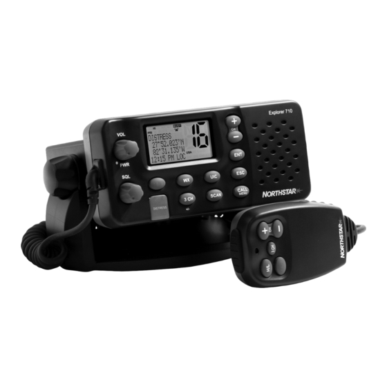
- Page 1 Explorer 710 VHF VHF Marine Radio Operation and Installation Manual www.northstarnav.com...
- Page 2 Please read carefully before installation and use. This is the safety alert symbol. It is used to alert you to potential personal injury hazards, Obey all safety messages that follow this symbol to avoid possible injury or death. WARNING indicates a potentially hazardous situation which, if not avoided, could result in death or serious injury CAUTION indicates a potentially hazardous situation which, if not avoided, could result in minor or moderate injury.
-
Page 3: Table Of Contents
Contents Section 1 - General Information ...5 1-1 Features ................5 1-2 Customizing your Northstar VHF Radio . - Page 4 Section 6 - Distress Calls ... 32 6-1 Sending a Distress Call ............32 6-2 Receiving a Distress Call (DISTRESS!) .
-
Page 5: Section 1 - General Information
Section 1 - General Information 1-1 Features Congratulations on your purchase of a Northstar VHF 710US, or 710EU marine band VHF radio. All of these models provide the following useful features: • Prominent channel display • Adjustable contrast settings for the LCD •... -
Page 6: How To Display And Navigate Menus
1-3 How to Display and Navigate Menus 1. Hold down MENU (or CALL/MENU). Note that only four menu items can be displayed at any one time on the screen. 2. Press + CH - to scroll up and down the menu until the cursor is positioned at the desired option. Press ENT to display that option. - Page 7 Symbol Meaning Transmitting. HI LO Transmission power. High (HI) 25 W or Low (LO) 1 W. Weather channel. WX ALT Weather Alert. Alarm beeps will sound. VHF 710US only. BUSY Receiver busy with an incoming signal. Priority channel is selected. Duplex operation.
-
Page 8: Basic Operation And Key Functions
1-6 Basic Operation and Key Functions All possible keys and their functions are listed. Note that some of the keys are not available depending on your Northstar VHF radio model. Function VOL/PWR Volume and Power. Turn clockwise to power on. Continue to turn until a comfortable volume is reached. - Page 9 Transmission Power. High (HI) 25 W or Low (LO) 1 W. Press to toggle between high or low transmission power for the entire channel bank. The HI or LO selection is shown on the LCD. Some channels allow only low power transmissions. Error beeps will sound if the power transmission setting is incorrect.
- Page 10 Press + or - to step through the available channels one at a time, or hold down to scroll rapidly through all the available channels. See Appendix C for a listing of channel charts. Alphanumeric Entry. This key can also be used for menu selection and for alpha- numeric entry.
-
Page 11: Section 2 - The Radio Menu (Menu)
Section 2 - The Radio Menu (MENU) 2-1 Radio Menu Options (Menu) The following options are available through MENU (or CALL/MENU): BUDDY LIST LOCAL/DIST BACKLIGHT CONTRAST GPS/DATA DSC SETUP RADIO SETUP GPS SIM RESET 1-3 and 1-4 explain how to navigate around the menu and enter, save and change data. Northtstar Explorer VHF Series: 710US, 710EU Operation and Installation Manual Maintain your buddy list. -
Page 12: Maintain Your Buddy List (Buddy List)
2-2 Maintain Your Buddy List (BUDDY LIST) VHF 710US and VHF 710EU only. MENU SELECT Use the Buddy List to store the names and associated MMSIDs of 20 favourite people. >BUDDY LIST Names are stored in the order of entry, with the most recent entry shown fi rst. LOCAL/DIST The following sections show to use BUDDY LIST to add, edit, and delete entries on BACKLIGHT... -
Page 13: Local Or Distance Sensitivity (Local/Dist)
2-2-3 Delete an Entry BUDDY LIST BUDDY LIST > MANUAL NEW ALEX Select BUDDY LIST. Press ENT to display the list of entries. Scroll down (if required) to the entry you want to delete and press ENT. Select DELETE then select YES. The entry is deleted immediately and the buddy list is displayed again. -
Page 14: Gps Data And Time (Gps/Data)
2-4-1 Set the Backlighting Level BACKLIGHT Note that the DISTRESS key backlighting cannot be switched off . 2.4.2 Set the Contrast Level CONTRAST 2-5 GPS Data and Time (GPS/DATA) If the boat has an operational GPS navigation receiver, the VHF radio automatically MENU SELECT detects and updates the vessel position and the local time. - Page 15 2-5-2 Local Time (TIME OFFSET) The local time can be set by entering the time off set between UTC and local time as follows. GPS/DATA MANUAL >SETTING Select GPS/DATA, then SETTING. Select TIME OFFSET to enter the diff erence between UTC and local time. Half hour increments can be used with a maximum off...
- Page 16 2-5-3 Time Format Options (TIME FORMAT) Time can be shown in 12 or 24 hour format. GPS/DATA MANUAL > SETTING 1. Select GPS/DATA, then SETTING. 2. Select TIME FORMAT. 3. Select 12 Hr or 24 Hr as desired. In this example, 12 hour format has been selected and so the LCD shows the AM or PM suffix.
-
Page 17: Gps Simulator (Simulator)
2-5-7 GPS Alert Options (ALERT) The GPS alert is usually set to ON (on) so that if the GPS navigation receiver is disconnected, the alarm sounds. GPS/DATA LL DISPLY COG/SOG > GPS ALERT 2-6 GPS Simulator (SIMULATOR) The GPS Simulator is set to OFF whenever the radio is turned ON or whenever real GPS data is available through the COM port. -
Page 18: Section 3 - Radio Setup Menu (Radio Setup)
Section 3 - Radio Setup Menu (RADIO SETUP) 3-1 Radio Setup Menu (RADIO SETUP) Edit or delete channel names. CH NAME See Section 3-2. Set the volume level of the incoming call notifi cation beeps. RING VOLUME See section 3-3. Set the volume level of the beeps. -
Page 19: Ring & Beep Volume (Ring Vol) And (Beep Vol)
3-3 RING & BEEP Volume (RING VOL) and (BEEP VOL) Set the volume level of the incoming signal beeps (RING VOLUME) and/or the error and warning beeps (BEEP VOLUME) to HIGH (high) or LOW (low) as follows: RADIO SETUP > CH NAME RING VOLUME BEEP VOLUME Select RADIO SETUP, then RING VOLUME or BEEP VOLUME as appropriate. -
Page 20: Weather Alert (Wx Alert)
3-6 Weather Alert (Wx ALERT) VHF 710US only. The NOAA provides several weather forecast channels on USA and Canadian channel banks. If severe weather such as storms or hurricanes are forecast, the NOAA broadcasts a weather alert on 1050 Hz. You can set up the radio to pick up weather alerts, as follows: RADIO SETUP INT SPEAKER... -
Page 21: Section 4 - Dsc Setup Menu (Dsc Setup)
Section 4 - DSC Setup Menu (DSC SETUP) These DSC facilities are available only on the 710US and 710EU and a valid user MMSID must be entered to access the DSC functions. 4-1 DSC Setup - Menu Options The following options are available: Enter your user MMSID. -
Page 22: Maintain Your Groups (Group Setup)
4-3 Maintain Your Groups (GROUP SETUP) Use GROUP SETUP to create, edit, or delete 1, 2, or 3 groups of frequently called people stored in alphanumeric order. A group MMSID always starts with 0. 4-3-1 Create a Group (GROUP SETUP) DSC SETUP GROUP SETUP USER MMSID... -
Page 23: Response To Individual Calls (Indiv Reply)
4-3-3 Delete a Group GROUP SETUP FISHER2 MANUAL NEW > FISHER2 FRIENDS1 Select DSC SETUP, then GROUP SETUP. The existing group names are displayed. Press + or - to scroll to the incorrect entry then press ENT. Select DELETE and press ENT. The radio asks for confi rmation. Press ENT to delete the group and return to the GROUP SETUP screen. -
Page 24: Dsc Functionality Options (Dsc Func)
VHF 710EU only. An ATIS MMSID always starts with the number 9. To enter or edit your ATIS MMSID: Select DSC SETUP, then ATIS MMSID. If this is the fi rst time that you are entering your ATIS MMSID, a dashed line appears. Enter your ATIS MMSID along the dashed line. -
Page 25: Response Type To Ll Polling Calls (Ll Reply)
There are two annunciators in the screen to show you the current mode: if the DSC annunciator is shown, DSC is operational. If the ATIS annunciator is shown, ATIS is operational. 4-7 Response Type to LL Polling Calls (LL REPLY) You can set up the radio to respond to an LL polling request in one of three ways: AUTO automatically replies to any incoming LL polling requests from any of your buddies. -
Page 26: Section 5 - Sending And Receiving Dsc Calls
Section 5 - Sending and Receiving DSC Calls These DSC facilities are available only on the VHF 710US and VHF 710EU models, and a valid user MMSID must have been entered to access the DSC functions. 5-1 WHAT IS DSC? DSC (Digital Selective Calling) is a semi-automated method of establishing VHF, MF, and HF radio calls. - Page 27 5-2-1 Make a Routine Call (Individual) DSC CALL INDIVIDUAL > INDIVIDUAL LAST CALL GROUP 012345678 12345678 INDIVIDUAL INDIVIDUAL ROUTINE ROUTINE > SEND? CALLING... You can call any other person that has another DSC equipped radio. Press CALL/MENU to enter DSC mode, then select INDIVIDUAL. This allows you to call another person. Select MANUAL NEW to call a person that is not in your buddy list, otherwise select the name of your buddy.
- Page 28 5-2-4 Recall the Most Recent Incoming Call (LAST) DSC CALL VHF710 USA INDIVIDUAL INDIVIDUAL > LAST CALL ROUTINE GROUP 10:22AM LOC This facility is useful and used frequently. Press CALL/MENU to enter DSC mode. LAST CALL is automatically selected. Press ENT to display the contact details of the most recent incoming call.
- Page 29 5-2-7 Call using the Call Log (CALL LOG) DSC CALL 11 VHF710 GROUP INDIVIDUAL ALL SHIPS ROUTINE > CALL LOG 10:45PM LOC VHF710 INDIVIDUAL ROUTINE > SEND? The Call Log contains the contact details for the 20 most recent incoming calls, so that you call any of them again quickly.
-
Page 30: Receiving Dsc Calls
5-2-9 Request the LL Position of a Buddy (LL REQUEST) DSC CALL LL REQUEST CALL LOG DIST LOG VHF710 > LL REQUEST BUDDY #3 channel name LL REQUEST AWAITING ACK Press CALL/MENU to enter DSC mode, then select LL REQUEST. Select the buddy whose LL position you want to request then press ENT to send the request. - Page 31 5-3-2 Receiving an Individual Call (INDIV) RCV: INDIV VHF710 ENTER –> ACK ESC –> EXIT If the radio recognises the user MMSID as one of your buddies, the buddy’s name is displayed in place of the user MMSID. 2. The VHF 710US responds automatically but the VHF 710EU prompts you to press ENT to acknowledge the incoming call.
-
Page 32: Section 6 - Distress Calls
Section 6 - Distress Calls This DSC function is available only on the 710US and 710EU models, and a valid user MMSID must have been entered to access this DSC function. 6-1 Sending a Distress Call DISTRESS CALL DISTRESS CALL >... -
Page 33: Receiving A Distress Call (Distress!)
6-2 Receiving a Distress Call (DISTRESS!) RCV: DISTRESS RCV: DISTRESS 123456789 10:34 UTC FLOODING 82º50.003'N ESC –> EXIT 27º45.543'W The radio automatically selects CH16 and displays the details of the distress call on the screen. Press PTT to establish voice contact. The details are displayed over two screens that alternate every 1.5 seconds;... -
Page 34: Appendix A - Technical Specifications
Appendix A - Technical Specifications Northstar VHF 710 US.EU GENERAL Power Supply: 13.6V DC. Current drain: Transmit 6 A at 25 W Tx / 1.5A at 1W Tx Receive Less than 250mA in standby Useable channels: International, USA, Canada, Weather (country specifi c) Mode: 16K0G3E (FM) / 16K0G2B (DSC) PHYSICAL... - Page 35 TRANSMITTER Frequency: 156.025 - 157.425 MHz Output power: 25 W / 1 W selectable Transmitter protection: Open / short circuit of antenna Max Freq deviation: +/- 5 kHz Spurious & harmonics: better than 2.5 μ W Modulation distortion: Less than 4%@ 1 kHz for a +/-3 kHz deviation RECEIVER Frequency: 156.025 - 163.275 MHz...
-
Page 36: Appendix B - Troubleshooting
Appendix B - Troubleshooting 1. The transceiver will not power up. A fuse may have blown OR there is no voltage getting to the transceiver. a) Check the power cable for cuts, breaks, or squashed sections. b) After checking the wiring, replace the 7 Amp fuse (2 spare fuses are supplied). c) Check the battery voltage. -
Page 37: Appendix C - Vhf Marine Channel Charts
Appendix C - VHF Marine Channel Charts C.1 International (EU-DSC ON) NOTE For assistance in understanding the Table, see notes a) to o) below. (WRC-2000) Channel Notes designator stations 156,025 156,050 m), o) 156,075 m), o) 156,100 m), o) 156,125 m), o) 156,150 m), o) - Page 38 Channel Notes designator stations 156,800 156,825 156,850 156,875 156,900 156,925 156,950 156,975 157,000 157,025 157,050 157,075 157,100 m), o) 157,125 m), o) 157,150 m), o) 157,175 m), o) 157,200 m), o) 157,225 m), o) 157,250 m), o) 157,275 m), o) 157,300 m), o) 157,325...
- Page 39 The frequencies in this Table may also be used for radiocommunications on inland waterways in accord- ance with the conditions specifi ed in No. 5.226. – 56 – 62238 IEC:2003(E) Administrations having an urgent need to reduce local congestion may apply 12,5 kHz channel interleav- ing on a non-interference basis to 25 kHz channels, provided: –...
- Page 40 C.2 USA Channel Chart SEND RECEIVE (MHz) (MHz) 156.050 156.050 156.150 156.150 156.250 156.250 156.300 156.300 156.350 156.350 156.400 156.400 156.450 156.450 156.500 156.500 156.550 156.550 156.600 156.600 156.650 156.650 156.700 156.700 RX Only 156.750 156.800 156.800 156.850 156.850 156.900 156.900 156.950 156.950 157.000 161.600 157.000 157.000...
- Page 41 SEND RECEIVE (MHz) (MHz) 156.075 156.075 156.175 156.175 156.225 156.225 156.275 156.275 156.325 156.325 156.375 156.375 156.425 156.425 156.475 156.475 156.525 156.525 156.575 156.575 156.625 156.625 156.675 156.675 156.725 156.725 156.875 156.875 156.925 156.925 156.975 156.975 157.025 157.025 157.075 157.075 157.125 157.125 157.175 157.175 157.225 161.825...
- Page 42 WEATHER Wx01 RX Only 162.550 Wx02 RX Only 162.400 Wx03 RX Only 162.475 Wx04 RX Only 162.425 Wx05 RX Only 162.450 Wx06 RX Only 162.500 Wx07 RX Only 162.525 Wx08 RX Only 161.650 Wx09 RX Only 161.775 Wx10 RX Only 163.275 SPECIAL NOTES ON USA CHANNEL USAGE LOW POWER (1 W) only.
- Page 43 C-3 CANADA Channel CHART SEND RECEIVE (MHz) (MHz) 156.050 160.650 156.100 160.700 156.150 160.750 156.200 156.200 156.250 156.250 156.300 156.300 156.350 156.350 156.400 156.400 156.450 156.450 156.500 156.500 156.550 156.550 156.600 156.600 156.650 156.650 156.700 156.700 156.750 156.750 156.800 156.800 156.850 156.850 156.900...
- Page 44 SEND RECEIVE (MHz) (MHz) RX Only 162.000 156.025 160.625 156.075 156.075 156.125 156.125 156.225 160.825 156.225 156.225 156.275 156.275 156.325 156.325 156.375 156.375 156.425 156.425 156.475 156.475 156.525 156.525 156.575 156.575 156.625 156.625 156.675 156.675 156.725 156.725 156.875 156.875 156.925 156.925 156.975 156.975...
- Page 45 WEATHER Wx01 RX Only 162.550 Wx02 RX Only 162.400 Wx03 RX Only 162.475 Wx04 RX Only 162.425 Wx05 RX Only 162.450 Wx06 RX Only 162.500 Wx07 RX Only 162.525 Wx08 RX Only 161.650 Wx09 RX Only 161.775 Wx10 RX Only 163.275 SPECIAL NOTES ON CANADA CHANNEL USAGE LOW POWER (1 W) only.
- Page 46 C-4 EU INLAND WATERWAY CHANNELS Country Specific For specifi c channel information for your country, please refer to local authorities. SPECIFIC FOOTNOTES FREQUENCY (MHZ) SHIP 156.025 156.05 156.075 156.1 156.125 156.15 156.175 156.2 156.225 156.25 156.275 a) b) 156.3 156.325 156.35 a) c) 156.375...
- Page 47 156.85 a) k) 156.875 156.9 156.925 156.95 156.975 157.025 157.05 157.075 157.1 l) m) 157.125 157.15 a) m) 157.175 157.2 157.225 157.25 a) m) 157.275 157.3 a) m) 157.325 157.35 a) d) 157.375 157.4 a) p) 157.425 AIS 1 a) n) 161.975 AIS 2 a) n)
- Page 48 1.1 General remarks to frequency table 1 1.1.1 The channels for service categories ship-to-ship and nautical information may also be used for vessel traffi c -sys tems by traffi c centres. 1.1.2 In some countries, frequencies certain channels are used for an other service category or other radio services.
-
Page 49: Appendix D - Mmsid And License Information
Special Channels SEND RECEIVE (MHz) (MHz) 156.000 156.000 157.425 157.850 161.425 161.425 157.550 162.150 96H 162.425 162.425 155.500 155.500 155.525 155.525 155.650 155.650 155.625 155.625 155.775 155.775 155.825 155.825 AIS1 161.975 161.975 AIS2 162.025 162.025 Note: Lightly Shaded Simplex channel CH00 is only available in the UK to Coast Guard users with written authorization. -
Page 50: Section 7 - Installation Section
Section 7 - Installation Section GPS NAVIGATION RECEIVER VHF ANTENNA This Northstar radio is designed to generate a digital maritime distress call to facilitate search and rescue. To be eff ective as a safety device, this radio must be used only within the geographic range of a shore-based VHF marine Channel 70 distress and safety watch system. - Page 51 Checklist (pictured over) The following items should be supplied in the box. Check before starting the installation and contact your dealer if an item is missing. Note that an antenna is not provided with the VHF Radio. Consult your Northstar dealer for advice if necessary.
- Page 52 Checklist (middle picture opposite) 16. Two fl ush mount kit brackets 17. Two M5x32 screws 18. Two M5x10 screws 19. Two lock nuts 20. Two plastic bulkhead bushings. 21. Installation template (not pictured) 22. One 7 Amp spare fuse (not pictured) in case of accidental reverse of the battery polarity Installation Options There are two ways to install the radio.
- Page 53 Gimbal Installation Hold the mounting gimbal at the chosen location and use a soft pencil to mark the screw hole positions onto the mounting surface. If you cannot reach behind the mounting surface to attach the nuts, use the 5mm self-tapping screws instead of the fl...
- Page 54 Changing the Viewing Angle The viewing angle has a 20º tilt range. To change the current viewing angle on a gimbal mount: Support the radio then loosen the mounting knobs until the radio can be moved. Re-position the radio then tighten the mounting knobs again. Recessed Installation (picture below) Tape the installation template onto the chosen location site.
- Page 55 Connect the Radio Cables - Rear view of base unit 1. VHF Antenna connection. (Antenna is not supplied.) 2. Combined power and speaker cable. The end of the power cable splits in two: BLACK. Earth. Connect to the (-) NEGATIVE battery terminal. RED.
- Page 56 User MMSID You must obtain a user MMSID (Marine Mobile Service Identity) and enter it into your 710 or 720 in order to use the DSC functions. Contact the appropriate authorities in your country. If you are unsure who to contact, consult your Northstar dealer.
- Page 57 30 Sudbury Road, Acton, MA 01720, USA Ph: +1 978.897.6600 Ph: +1 800.628.4487 Fax: +1 978.897.7241 sales@bntmarine.com Gladesville, NSW 2111, Ph: +61 2 9879 9060 Fax: +61 2 9879 9009 northstaraus@northstarnav.com MN000599A-G AMERICAS EUROPE Unit 2, Ocean Quay, Belvidere Rd, Southampton, SO14 5QY, ENGLAND Ph: +44 2380 339922 Fax: +44 2380 330345...