Advertisement
Model No. NTS5925.0
Serial No.
Write the serial number in the
space above for future reference.
Serial Number Decal
QUESTIONS?
As a manufacturer, we are com-
mitted to providing complete
customer satisfaction. If you
have questions, or if a part is
damaged or missing, PLEASE
CONTACT OUR CUSTOMER
SERVICE DEPARTMENT
DIRECTLY.
CALL TOLL-FREE:
1-888-825-2588
Mon.–Fri., 6 a.m.–6 p.m. MST
ON THE WEB:
www.nordictrackservice.com
CAUTION
Read all precautions and instruc-
tions in this manual before using
this equipment. Save this manual
for future reference.
USER'S MANUAL
Visit our website at
www.nordictrack.com
new products, prizes,
fitness tips, and much more!
Advertisement
Table of Contents

Related Manuals for NordicTrack NTS5925.0


Summary of Contents for NordicTrack NTS5925.0
- Page 1 Model No. NTS5925.0 Serial No. Write the serial number in the space above for future reference. Serial Number Decal QUESTIONS? As a manufacturer, we are com- mitted to providing complete customer satisfaction. If you have questions, or if a part is...
-
Page 2: Table Of Contents
Note: A PART IDENTIFICATION CHART and a PART LIST/EXPLODED DRAWING are attached in the center of this manual. Remove the PART IDENTIFICATION CHART and PART LIST/EXPLODED DRAWING before begin- ning assembly. NordicTrack is a registered trademark of ICON IP, Inc. -
Page 3: Warning Decal Placement
WARNING DECAL PLACEMENT The decal shown here has been placed on the resistance system. If the decal is missing or illegible, please call the toll-free telephone number on the front cover of this manual and order a free replacement decal. Apply the decal in the location shown. -
Page 4: Important Precautions
IMPORTANT PRECAUTIONS WARNING: To reduce the risk of serious injury, read the following important precautions before using the resistance system. 1. Read all instructions in this manual and all warnings on the resistance system before using the resistance system. Use the resist- ance system only as described in this manu- 2. -
Page 5: Before You Begin
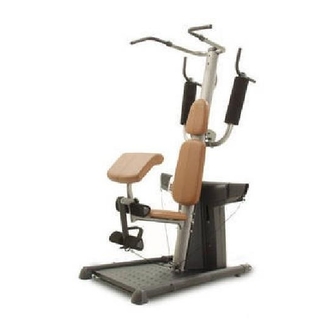
The model number is NTS5925.0. The serial number can be found on a decal attached to the exercise rack (see the front cover of this manual). -
Page 6: Assembly
ASSEMBLY Make Things Easier for Yourself Everything in this manual is designed to ensure that the resistance system can be assembled successfully by anyone. However, the resistance system has many parts and the assembly process will take time. By setting aside plenty of time, assembly will go smoothly. - Page 7 3. Attach the Upright Base (2) to the Base (1) with four M10 x 60mm Bolts (80), four M10 Washers (91), and four M10 Nylon Locknuts (74). Do not tighten the Locknuts yet. 4. Attach the Upright (3) to the Upright Base (2) with five M10 x 25mm Button Bolts (99) and five M10 Washers (91).
- Page 8 5. Orient the Backrest (16) as shown. Attach the Backrest to the Upright Base (2) and the Upright (3) with two M6 x 100mm Screws (71) and two M6 Washers (85). 6. Attach the Center Cover (59) to the Front Mech Cover (13) with two M4 x 20mm Self-tapping Screws (94).
- Page 9 8. Attach a Pull-up Handle (18) to the Top Frame (4) with four M10 x 20mm Button Bolts (83) and four M10 Washers (91). Slide a Top Arm Cap (20) over the Pull-up Handle (18) and onto the Top Frame (4). Press a 32mm Round Outer Cap (22) onto the Pull-up Handle (18).
- Page 10 11. Grease an M10 x 217mm Bolt (73). Attach the Dip Arm (5) to the Upright (3) with the Bolt and an M10 Nylon Locknut (74). Do not overtighten the Locknut; the Dip Arm must be able to pivot easily. Attach the Pin (58) to the Upright (3) with an M4 x 20mm Self-tapping Screw (94).
- Page 11 14. Grease an M10 x 72mm Bolt (101). Attach the Leg Lever (8) to the Seat Frame (6) with the Bolt and an M10 Nylon Locknut (74). Do not over- tighten the Locknut; the Leg Lever must be able to pivot easily. 15.
-
Page 12: Adjustments
ADJUSTMENTS This section explains how to adjust the resistance system. See the EXERCISE GUIDELINES on page 16 for important information about how to get the most benefit from your exercise program. Also, refer to the accompa- nying exercise guide to see the correct form for each exercise. Make sure all parts are properly tightened each time the resistance system is used. - Page 13 ADJUSTING THE DIP ARM To perform some exercises, the Dip Arm (5) should be locked in the up position. Remove the Pin (58) and lift the Dip Handle (11). Engage the Pin into the Upright (3) and the hole in the Dip Arm plate. To use the Dip Arm (5), remove the Pin (58) and lower the Dip Handle (11).
- Page 14 ATTACHING THE CURL PAD To use the Curl Pad (29), first remove the 50mm Round Slanted Inner Cap (66) from the Seat Frame (6). Then, insert the Curl Post (9) into the Seat Frame and secure the Curl Post with the Curl Knob (64). Remove the Curl Pad (29) and replace the 50mm Round Slanted Inner Cap (66) when performing an exercise that does not require the Curl Pad.
- Page 15 THE RESISTANCE SYSTEM CONSOLE Resistance. To adjust the resistance level, first make sure that no cables are being pulled. Then, press the LBS Up or Down button. The resistance level will be displayed in the top display. Rep Counter. Press the REPS Up or Down button until the center display shows the desired number of repetitions to be completed for an exercise.
- Page 16 Rest for a short period of time after each set. The ideal resting periods are: • Rest for three minutes after each set for a muscle building workout. • Rest for one minute after each set for a toning work- out.
-
Page 17: Exercise Guidelines
EXERCISE GUIDELINES THE FOUR BASIC TYPES OF WORKOUTS Muscle Building To increase the size and strength of your muscles, push them to a high percentage of their maximum capacity. Your muscles will continually adapt and grow as you progressively increase the intensity of your exercise. - Page 18 EXERCISE MONDAY Date: AEROBIC EXERCISE TUESDAY Date: EXERCISE WEDNESDAY Date: THURSDAY AEROBIC EXERCISE Date: EXERCISE FRIDAY Date: Make photocopies of this page for scheduling and recording your workouts. WEIGHT WEIGHT WEIGHT SETS REPS SETS REPS SETS REPS...
- Page 19 EXERCISE MONDAY Date: AEROBIC EXERCISE TUESDAY Date: EXERCISE WEDNESDAY Date: THURSDAY AEROBIC EXERCISE Date: EXERCISE FRIDAY Date: Make photocopies of this page for scheduling and recording your workouts. WEIGHT WEIGHT WEIGHT SETS REPS SETS REPS SETS REPS...
-
Page 20: Part Identification Chart
PART IDENTIFICATION CHART Refer to the drawings below to identify small parts used in assembly. The number in parentheses by each draw- ing is the key number of the part, from the PART LIST in the center of this manual. Note: Some small parts may have been pre-attached. - Page 21 PART LIST—Model No. NTS5925.0 No. Qty. Description Base Upright Base Upright Top Frame Dip Arm Seat Frame Base Plate Leg Lever Curl Post Mech Frame Dip Handle Back Mech Cover Front Mech Cover Swivel Arm Seat Backrest Headrest Pull-up Handle...
- Page 22 EXPLODED DRAWING A—Model No. NTS5925.0 R0306A...
- Page 23 EXPLODED DRAWING B—Model No. NTS5925.0 R0306A...
-
Page 24: Ordering Replacement Parts
LIMITED WARRANTY WHAT IS COVERED—The entire NordicTrack resistance system (“Product”) is warranted to be free of all defects in material and workmanship. WHO IS COVERED—The original purchaser or any person receiving the Product as a gift from the original purchaser.