Table of Contents
Advertisement
Advertisement
Table of Contents

Related Manuals for RiTTO Twinbus 1 7630


Summary of Contents for RiTTO Twinbus 1 7630
- Page 1 RITTO TWINBUS Issue 04.2007/lD No. 400 232 681-GB QUICK REFERENCE MANUAL Door Intercom and Video Systems with TwinBus Power Supply Unit 1 7573/01 General Information Installation Assembly Starting Up Door Station/Power Supply Units Service ® einfach planen sicher installieren.
-
Page 2: Table Of Contents
Contents Before continuing… Using this document .........3 Explanation of symbols used . -
Page 3: Before Continuing
It does not replace the system manual. It provides a basic overview for the most frequent use of door intercom and video systems in single or multi-family residential buildings. Only those devices specified in the Contents are described. The system manual can be ordered free of charge via the Internet at www.ritto.de or from +49 (0) 02773/812-0. -
Page 4: List Of Abbreviations
/7 . Colour: white / . 0 Device index This document only specifies information on the respective device. Please refer to the RITTO Manual for the colours available and current device versions. General Information Cable networks Existing lines can be used as bus lines. We recommend the following, commercially available telecommunication lines:... -
Page 5: Maximum Line Lengths
Discharge electrostatic charges before touching the equipment. Intended use The RITTO door intercom is a system devised for controlling access and internal communication inside residential buildings. Any other use is considered unintended use. The manufacturer is not deemed liable for any damage resulting from unintended use. -
Page 6: Video Camera Installation Location
EC Directive "Electromagnetic Compatibility" 89/336/EEC or 2004/108/EC (complying with the currently valid version). Directives on low-voltage 72/23/EEC (complying to the currently valid version). RITTO TwinBus devices bear the CE approval label. Conformity has been certified. The corresponding documents are held by the manufacturer. Warranty The general terms of business implemented by RITTO GmbH &... -
Page 7: Assembly
Assembly Assembly Power supply unit and additional devices 00903-0 00822-0 00904-0 00538-0... -
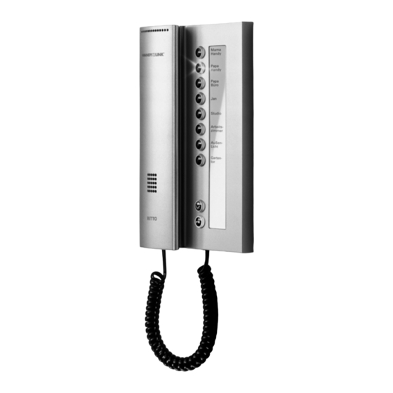
Page 8: Twinbus Indoor Telephone 1 7630, 1 7650
Assembly TwinBus indoor telephone 1 7630, 1 7650 The following section describes the assembly of the TwinBus indoor telephone 1 7630. The assembly of the TwinBus comfort indoor telephone 1 7650 is performed identically. Connection A Standard connection B Doorbell connecting option using 3 wires Note: Button adapter 1 4645 must be used when... -
Page 9: Twinbus Indoor Video Stations 1 7855, 1 7857
Assembly TwinBus indoor video stations 1 7855, 1 7857 Surface-mounted ➤ ➤ Remove the TwinBus device and the supplied com- Please remove the clamps from the packaging. ponents from the packaging. ➤ Please provide your customers with a copy of the operating instructions for the TwinBus device. -
Page 10: Installation
Installation Installation Door intercom for single or multi-family residence Each residential unit can be accessed separately from the main entrance. The doorbell for the apartment door is con- nected directly to the indoor telephone. Incoming calls from the door station and the apartment door (ED) are auto- matically indicated by different ringing tones. -
Page 11: Video Door Intercom For Single Or Multi-Family Residence
Installation Video-door intercom for single or multi-family residence with one main bus line with handsfree video intercom unit 1 7835, 1 7845, or indoor video station 1 7855, 1 7857 with decentral power supply 1 6477 1 7857 1 6477 1 7857 1 4783 1 6477... - Page 12 Installation Video door intercom for single or multi-family residence with 3 main bus lines and indoor video stations 1 7855, 1 7857, or handsfree video station 1 7835, 1 7845 with central power supply and line distributor 1 4813 max. 12 max.
- Page 13 Installation 1 7857 Va Vb 51 52 1 7857 1 7857 Va Vb 51 52 max. 12 max. 12 max. 12 1 4874 1 7573 a1 b a2 b a3 b 1 4813 1 6477 1 4783 RiTT O 1 4760 1 4753 S0118-1 * Please note the red mark –...
-
Page 14: Starting Up
Starting up Starting up The system can be started using the indoor telephone, indoor video unit or apartment doorbell button. Start-up using the apartment button is useful if you do not have access to the residential unit. In order to allow the operator to change the call tone of the main bell button, the main bell button must be programmed as the main button when initial setting takes place. - Page 15 Starting up Start-up using the apartment button Activity Result LD 2 LD 1 Flashes red, Press and hold "P" Flashes until yellow goes out Within Acoustic sig- three minutes, go to nal for the apartment but- confirmation ton. Press and hold it for 5 sec Within one minute, Acoustic signal for con-...
-
Page 16: Door Station/Power Supply Units
Door station/power supply units Door station/power supply units Bus connector in the door station The door station modules are connected to the bus connectors one under the other. The wires in the door station bus connector marked red must be attached to the pin labelled "red" on the board. As a result, the door station modules are numbered identically. -
Page 17: Twinbus Built-In Loudspeaker 1 4921
Door station/power supply units Note: Use an additional mains transformer 1 6476 if you are operating the modular Portier door station with more than 6 illuminated modules. TwinBus built-in loudspeaker 1 4921 Device description Built-in loudspeaker 1 4921 is integrated in an existing bell or letter box system in order to convert it into a TwinBus door station. -
Page 18: Twinbus Extension Unit 1 4923
Door station/power supply units TwinBus extension unit 1 4923 Expansion unit 1 4923 is used to expand built-in loudspeaker 1 4921. It allows an additional 12 bell buttons to be connected. 00213-0 00279-0 * Please note the red mark – see “Bus connections in the door station” on page ☞ 16. Note: Customer-installed illumination up to max. -
Page 19: Twinbus Power Supply Unit 1 7573
Door station/power supply units TwinBus power supply unit 1 7573 Device description The power supply provides the power for the devices attached to the TwinBus. It controls the door station and provi- des functions that the connected subscribers can use. Connections L, N 230 V mains connection... -
Page 20: Twinbus Door Selector Switch 1 4982
Door station/power supply units Delete settings Activity Result Press "P" until LD 1 is lit and then "Z" yellow briefly Activating/deactivating adjustment protection Activity Result Press until LD 3 Prog. prot. is lit green Press until LD 3 (green) Prog. prot. goes out Note: Adjustment protection remains in effect after activation on the TwinBus power supply unit... - Page 21 Door station/power supply units 1 7630 1 7630 1 7630 1 7573 1 2 3 4 11 a1 b 1 4982 A2 A21 B2 B21 Va Vb Va Vb Va Vb RiTT O 1 4760 1 4753 RiTT O 1 4760 1 4753 S0003-2 * Please note the red mark –...
-
Page 22: Power Supply Unit Video 1 4874
Door station/power supply units Video power supply unit 1 4874 Device description The Video power supply unit 1 4874 is used as the main power supply for up to 12 indoor video stations or handsfree intercom units. No manual power on rights may be set and no parallel operation planned. Connection ☞... -
Page 23: Service
Service Service Measuring points TwinBus power supply unit 1 7573 Clamp Load Target voltage open/switched 24 V DC to 30 V DC open/switched 24 V DC to 30 V DC open/switched 24 V DC to 30 V DC no door communication 0 V DC with door communication 24 V DC... -
Page 24: Service Indicators
LED 6 (yellow) illuminates Direct current indicator (bus voltage) LED 7 (yellow) illuminates Alternating current indicator (door opener) LED 8 (red) illuminates Door opener relay has switched. RITTO GmbH & Co. KG Rodenbacher Straße 15 D-35708 Haiger/Germany Phone +49(0)2773/812-0 +49(0)2773/812-999 www.ritto.de • info@ritto.de...