Table of Contents
Advertisement
FCC Information and Copyright
This equipment has been tested and found to comply with the limits of a Class B
digital device, pursuant to Part 15 of the FCC Rules. These limits are designed
to provide reasonable protection against harmful interference in a residential
installation. This equipment generates, uses, and can radiate radio frequency
energy and, if not installed and used in accordance with the instructions, may
cause harmful interference to radio communications. There is no guarantee that
interference will not occur in a particular installation.
The vendor makes no representations or warranties with respect to the contents
here and specially disclaims any implied warranties of merchantability or fitness
for any purpose. Further the vendor reserves the right to revise this publication
and to make changes to the contents here without obligation to notify any party
beforehand.
Duplication of this publication, in part or in whole, is not allowed without first
obtaining the vendor's approval in writing.
The content of this user's manual is subject to be changed without notice and we
will not be responsible for any mistakes found in this user's manual. All the brand
and product names are trademarks of their respective companies.
H81MG Setup Manual
Dichiarazione di conformità
sintetica
Ai sensi dell'art. 2 comma 3 del D.M.
275 del 30/10/2002
Si dichiara che questo prodotto è
conforme alle normative vigenti e
soddisfa i requisiti essenziali richiesti
dalle direttive
2004/108/CE, 2006/95/CE e
1999/05/CE
quando ad esso applicabili
Short Declaration of conformity
We declare this product is complying
with the laws in force and meeting all
the essential requirements as specified
by the directives
2004/108/CE, 2006/95/CE and
1999/05/CE
whenever these laws may be applied
Advertisement
Table of Contents

Related Manuals for Biostar H81MG


Summary of Contents for Biostar H81MG
- Page 1 H81MG Setup Manual FCC Information and Copyright This equipment has been tested and found to comply with the limits of a Class B digital device, pursuant to Part 15 of the FCC Rules. These limits are designed to provide reasonable protection against harmful interference in a residential installation.
-
Page 2: Table Of Contents
Table of Contents Chapter 1: Introduction .................1 Before You Start................. 1 Package Checklist ..............1 Motherboard Specifications ............2 Rear Panel Connectors ............. 3 Motherboard Layout ..............4 Chapter 2: Hardware Installation ............5 Install Central Processing Unit (CPU) ........5 Install a Heatsink ............... -
Page 3: Chapter 1: Introduction
H81MG CHAPTER 1: INTRODUCTION 1.1 Before You Start Thank you for choosing our product. Before you start installing the motherboard, please make sure you follow the instructions below: Prepare a dry and stable working environment with sufficient lighting. Always disconnect the computer from power outlet before operation. -
Page 4: Motherboard Specifications
1x Serial Port Header 1x S/PDIF out Connector 1x Printer Port Header Form Factor ATX Form Factor, 226 mm x 174 mm Windows 7/ 8 OS Support Biostar reserves the right to add or remove support for any OS with or without notice. -
Page 5: Rear Panel Connectors
H81MG 1.4 Rear Panel Connectors Note1: DVI-D & VGA ports only work with an Intel® integrated Graphics Processor. Note2: Maximum resolution: DVI: 1920 x 1200 @60Hz VGA: 1920 x 1200 @60Hz Note3: To configure 7.1-channel audio, you have to use a chassis with HD front panel audio module and enable the multi-channel audio feature through O.S. -
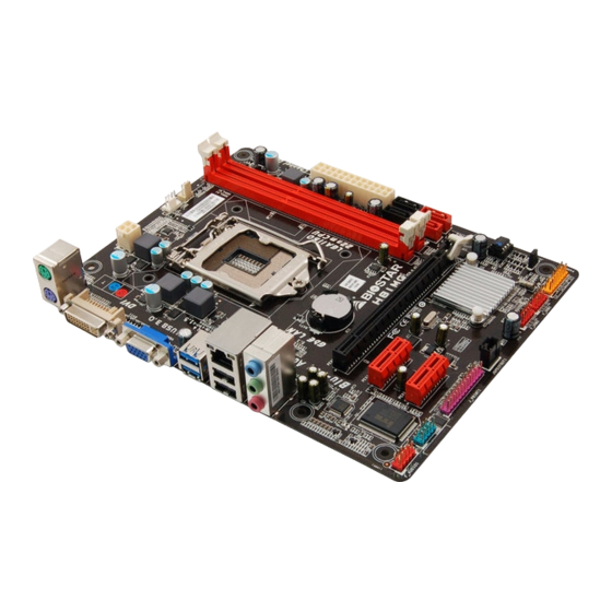
Page 6: Motherboard Layout
Motherboard Manual 1.5 Motherboard Layout Note: ■ represents the 1 pin. -
Page 7: Chapter 2: Hardware Installation
H81MG CHAPTER 2: HARDWARE INSTALLATION 2.1 Install Central Processing Unit (CPU) Step 1: Locate the CPU socket on the motherboard Note1: Remove Pin Cap before installation, and make good preservation for future use. When the CPU is removed, cover the Pin Cap on the empty socket to ensure pin legs won’t be damaged. - Page 8 Motherboard Manual Step 4: Hold processor with your thumb and index fingers, oriented as shown. Align the notches with the socket. Lower the processor straight down without tilting or sliding the processor in the socket. Note1: The LGA1155 CPU is not compatible with LGA 1150 socket. Do not install a LGA 1155 CPU on the LGA 1150 socket.
-
Page 9: Install A Heatsink
H81MG 2.2 Install a Heatsink Step 1: Place the CPU fan assembly on top of the installed CPU and make sure that the four fasteners match the motherboard holes. Orient the assembly and make the fan cable is closest to the CPU fan connector. -
Page 10: Connect Cooling Fans
Motherboard Manual 2.3 Connect Cooling Fans These fan headers support cooling-fans built in the computer. The fan cable and connector may be different according to the fan manufacturer. CPU_FAN1: CPU Fan Header Assignment Ground +12V FAN RPM rate sense Smart Fan Control (By Fan) SYS_FAN1: System Fan Header Assignment Ground... -
Page 11: Install System Memory
H81MG 2.4 Install System Memory DDR3 Modules Step 1: Unlock a DIMM slot by pressing the retaining clips outward. Align a DIMM on the slot such that the notch on the DIMM matches the break on the slot. Step 2: Insert the DIMM vertically and firmly into the slot until the retaining clips snap back in place and the DIMM is properly seated. -
Page 12: Expansion Slots
Motherboard Manual Memory Capacity DIMM Socket Total Memory Size DDR3 Module Location DDR3_A1 512MB/1GB/2GB/4GB/8GB Max is 16GB. DDR3_B1 512MB/1GB/2GB/4GB/8GB Dual Channel Memory Installation Please refer to the following requirements to activate Dual Channel function: Install memory module of the same density in pairs, shown in the table. Dual Channel Status DDR3_A1 DDR3_B1... - Page 13 H81MG PEX16_1: PCI-Express Gen2 x16 Slot PCI-Express 2.0 compliant. Maximum theoretical realized bandwidth of 8GB/s simultaneously per direction, for an aggregate of 16GB/s totally. PEX1_1/1_2: PCI-Express Gen2 x1 Slots PCI-Express 2.0 compliant. Data transfer bandwidth up to 500MB/s per direction; 1GB/s in total...
-
Page 14: Jumper Setting
Motherboard Manual 2.6 Jumper Setting The illustration shows how to set up jumpers. When the jumper cap is placed on pins, the jumper is “close”, if not, that means the jumper is “open”. Pin opened Pin closed Pin1-2 closed JCMOS1: Clear CMOS Jumper Placing the jumper on pin2-3, it allows user to restore the BIOS safe setting and the CMOS data. -
Page 15: Headers & Connectors
H81MG 2.7 Headers & Connectors ATXPWR1: ATX Power Source Connector For better compatibility, we recommend to use a standard ATX 24-pin power supply for this connector. Make sure to find the correct orientation before plugging the connector. Assignment Assignment +3.3V +3.3V... - Page 16 Motherboard Manual PANEL1: Front Panel Header This 16-pin header includes Power-on, Reset, HDD LED, Power LED, and speaker connection. It allows user to connect the PC case’s front panel switch functions. Assignment Function Assignment Function Speaker Connector Speaker Power LED (+) Power LED HDD LED (+) Power LED (+)
- Page 17 H81MG SATA3~SATA4: Serial ATA 2.0 Connectors These connectors connect to SATA hard disk drives via SATA cables. It satisfies the SATA 2.0 specification and with transfer rate of 3.0Gb/s. Assignment Ground Ground Ground F_USB1/2: Header for USB 2.0 Ports at Front Panel This header allows user to add additional USB ports on the PC front panel, and also can be connected with a wide range of external peripherals.
- Page 18 Motherboard Manual F_AUDIO1: Front Panel Audio Header This header allows user to connect the chassis-mount front panel audio I/O which supports HD and AC’97 audio standards. HD Audio AC’97 Assignment Assignment Mic Left in Mic In Ground Ground Mic Right in Mic Power GPIO Audio Power...
- Page 19 H81MG J_PRINT1: Printer Port Header This header allows user to connect a printer to the PC. Assignment Assignment -Strobe Ground -ALF Data 6 Data 0 Ground -Error Data 7 Data 1 Ground -Init -ACK Data 2 Ground -Scltin Busy Data 3...
-
Page 20: Chapter 3: Uefi Bios & Software
CD-ROM, or from the file location on the Web. BIOSTAR BIOS Flasher BIOSTAR BIOS Flasher is a BIOS flashing utility providing you an easy and simple way to update your BIOS via USB pen drive. Note1: This utility only allows storage device with FAT32/16 format and single partition. - Page 21 H81MG 6. Select the proper BIOS file, and a message asking if you are sure to flash the BIOS file. Click Yes to start updating BIOS. 7. A dialog pops out after BIOS flash is completed, asking you to restart the system.
- Page 22 Reset to restart the computer. Then, the BIOS Update is completed. BIOS Update Utility (through a BIOS file) 1. Installing BIOS Update Utility from the DVD Driver. 2. Download the proper BIOS from http://www.biostar.com.tw/ 3. Launch BIOS Update Utility and click the Update BIOS button on the main screen.
- Page 23 H81MG 4. A warning message will show up to request your agreement to start the BIOS update. Click OK to start the update procedure. 5. Choose the location for your BIOS file in the system. Please select the proper BIOS file, and then click on Open.
-
Page 24: Software
Motherboard Manual 3.3 Software Installing Software Insert the Setup DVD to the optical drive. The driver installation program would appear if the Auto-run function has been enabled. Select Software Installation, and then click on the respective software title. Follow the on-screen instructions to complete the installation. Launching Software After the installation process is completed, you will see the software icon showing on the desktop. - Page 25 H81MG eHot-Line eHot-Line is a convenient utility that helps you to contact with our Tech-Support system. This utility will collect the system information which is useful for analyzing the problem you may have encountered, and then send these information to our tech-support department to help you fix the problem.
- Page 26 Note2: If you are not using Outlook Express as your default e-mail client application, you may need to save the system information to a .txt file and send the file to our tech support with other e-mail application. Go to the following website http://www.biostar.com.tw/app/en/about/contact.php getting our contact information.
-
Page 27: Smart Connect Technology
H81MG Smart Connect Technology Intel® Smart Connect Technology is designed to update programs by periodically waking your computer from sleep/standby mode for a short time. This function works with applications that automatically get their data from the Internet. System Requirement: Intel Smart Connect Technology enabled in BIOS Setup Set the “ACPI Sleep State”... - Page 28 Motherboard Manual Basic and advanced settings Basic Tab Update Frequency slider: This slider bar sets the amount of time the feature waits to wake your computer and update your applications. Move the slider in the user interface to change the frequency. The slider bar can be set to wake and update your computer from every 15 to 60 minutes.
-
Page 29: Rapid Start Technology
H81MG Rapid Start Technology Intel® Rapid Start technology enables your system to get up and running faster from even the deepest sleep, saving time and power consumption. Feel secure knowing that your system will still resume to working conditions in the event of unexpected power loss while in sleep mode. - Page 30 Motherboard Manual 3-3 After rebooting, the system will setup Intel® Rapid Start Technology automatically. We recommend you restart the system after this installation is complete, Step 4: Configuring Intel® Rapid Start Application Launch the Intel® Rapid Start Technology Manager application from [Start] > [All Programs] >...
-
Page 31: Chapter 4: Useful Help
H81MG CHAPTER 4: USEFUL HELP 4.1 Driver Installation After you installed your operating system, please insert the Fully Setup Driver DVD into your optical drive and install the driver for better system performance. You will see the following window after you insert the DVD The setup guide will auto detect your motherboard and operating system. -
Page 32: Ami Bios Beep Code
Motherboard Manual 4.2 AMI BIOS Beep Code Boot Block Beep Codes Number of Beeps Description Continuing Memory sizing error or Memory module not found POST BIOS Beep Codes Number of Beeps Description Success booting. Display memory error (system video adapter) 4.3 Troubleshooting Probable Solution... - Page 33 H81MG CPU Overheated If the system shutdown automatically after power on system for seconds, that means the CPU protection function has been activated. When the CPU is over heated, the motherboard will shutdown automatically to avoid a damage of the CPU, and the system may not power on again.
-
Page 34: Appendix: Specifications In Other Languages
اﻟﻤﺄﺧﺬ ﻗﺎﻋﺪة وﺣﺪة اﻟﻤﻌﺎﻟﺠﺔ واط thermal design power – اﻟﺤﺪ اﻷﻗﺼﻰ ﻟﻠﻄﺎﻗﺔ اﻟﺤﺮارﻳﺔ ﻓﻲ ﺗﺼﻤﻴﻢ اﻟﻤﻌﺎﻟﺞ اﻟﻤﺮآﺰﻳﺔ ﻟﻘﺎﺋﻤﺔ دﻋﻢ اﻟﻤﻌﺎﻟﺞ www.biostar.com.tw ﻳﺮﺟﻰ اﻟﺮﺟﻮع إﻟﻰ اﻟﻤﻮﻗﻊ IINTEL® H81 ﻣﺠﻤﻮﻋﺔ اﻟﺸﺮاﺋﺢ . ار دي ﺗﺪﻋﻢ ﻗﻨﺎة ﻣﺰدوﺟﺔ دي DDR3 1066/ 1333/ 1600 ﺟﻴﺠﺎﺑﺎﻳﺖ... -
Page 35: French
1x Connecteur sortie S/PDIF 1x Embase port imprimante Facteur Facteur d'encombrement ATX, 226 mm x 174 mm d'encombrement Windows 7/ 8, Biostar se réserve le droit d’ajouter ou d'enlever le support pour toute SE Support SE avec ou sans préavis. -
Page 36: German
1x Header für klares CMOS 1x Serieller Port-Header 1x S/PDI-Auswurfsverbindung 1x Header für Druckeranschluss Formfaktor ATX Formfaktor, 226 mm x 174 mm Windows 7/ 8 OS-Unterstützung Biostar reserves the right to add or remove support for any OS with or without notice. -
Page 37: Italian
Connettore esterno S/PDIF x1 Distributore Slot Stampante x1 Fattore di Forma Fattore di Forma ATX, 226 mm x 174 mm Windows 7/ 8 Supporto SO Biostar si riserva il diritto di aggiungere o ritirare il supporto per qualsiasi SO con o senza preavviso. -
Page 38: Japanese
1x フロント パネル ヘッダー 1x フロント オーディオ ヘッダー 1x クリア CMOS ヘッダー 1x シリアル ポート ヘッダー 1x S/PDIF アウト コネクタ 1x プリンター ポート ヘッダー ATX フォーム ファクタ、226 mm x 174 mm フォーム ファクタ Windows 7/ 8 サポート OS Biostar には、通知なしでサポート OS を変更する権限があります。... -
Page 39: Polish
Port szeregowy x1 Port zewnętrzny S/PDIF x1 Złącze port drukarki x1 Obudowa Obudowa ATX, 226 mm x 174 mm Windows 7/ 8 Obsługa OS Biostar zastrzega sobie prawo do dodania lub wycofania obsługi dla OS, z wypowiedzeniem lub bez wypowiedzenia. -
Page 40: Portuguese
Conector Externo S/PDIF x1 Dispositivo Porta Impressora x1 Fator de Fôrma Fator de Fôrma ATX, 226 mm x 174 mm Windows 7/ 8 Suporte OS Biostar reserva seu direito de adicionar ou retirar o suporte para qualquer OS com ou sem notificação. -
Page 41: Russian
1 контакт микросхемы Clear CMOS 1 контакт последовательного порта 1 соединитель S/PDIF-Out 1 контакт порта принтера Конструктив Форм-фактор ATX, 226 мм x 174 мм Windows 7/ 8 Поддержка ОС Biostar оставляет за собой право добавлять или удалять поддержку любой ОС, с уведомлением или без. -
Page 42: Spanish
Conector Externo S/PDIF x1 Distribuidor Ranura Impresora x1 Factor de Forma Factor de Forma ATX, 226 mm x 174 mm Windows 7/ 8 Soporte OS Biostar reserva su derecho de añadir o retirar el soporte para cada OS con o sin notificación. 2013/07/04...