Advertisement
Quick Links
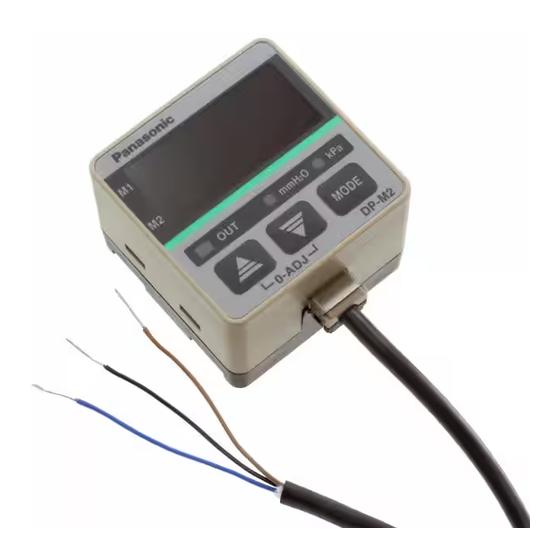
LED Display Digital Differential Pressure Sensor
DP-M Series
Thank you very much for purchasing Panasonic products. Please
read this Instruction Manual carefully and thoroughly for the
correct and optimum use of this product. Kindly keep this manual
in a convenient place for quick reference.
Never use this product as a sensing device for
personnel protection.
In case of using sensing devices for personnel protec-
tion, use products which meet laws and standards,
such as OSHA, ANSI or IEC etc., for personnel
protection applicable in each region or country.
WARNING
In case this sensor is used within Japan, SI unit
must be used since use of pressure units in Japan
is restricted to SI units.
1
SPECIFICATIONS
Type
Item
Model No.
Type of pressure
Rated pressure range
Set pressure range
Setting resolution
Pressure withstandability
Applicable fluid
Supply voltage
12 to 24V DC
Current consumption
50mA or less
NPN open-collector transistor
Maximum sink current: 100mA
Applied voltage: 30V DC or less
Comparative output
Residual voltage: 1V or less (at 100mA sink current)
Selectable either Normally open (NO) or Normally closed
(NC) by the keys.
Output operation
Refer to '
operation] for more details.
Hysteresis
Repeatability
Response time
Short-circuit protection
Analog current output
Display
3 digit red LED display (Sampling rate: 4 times/sec. approx.)
Displayable
pressure range
Operation
Orange LED (lights up when the comparative output is ON)
Red LED (The indicator corresponding to the selected unit
Pressure unit
lights up during the sensing mode.)
M1 setting
M2 setting
Ambient temperature
0 to +50
Ambient humidity
Over ambient temperature range 0 to +50 :
Temperature characteristics
Pressure port
Material
2
0.18mm
Cable
cabtyre cable, 2m long
Weight
INSTRUCTION MANUAL
For use outside Japan
MJE-DPM No.0050-31V
Standard
With analog current output
DP-M2
DP-M2A
Differential pressure
0 to 2.00 kPa.D {0 to 204 mmH
O.D}
2
0 to 2.00 kPa.D {0 to 204 mmH
O.D}
2
0.01 kPa.D {1 mmH
O.D}
2
6 kPa.D {612 mmH
O.D}
2
Non-corrosive gas
+10
% Ripple P-P 10% or less
-15
75mA or less
(between comparative output and 0V)
0.4V or less (at 16mA sink current)
8
SETTING' [Output mode and output
0.01 kPa.D {1mm H
O.D}
2
Within
1% F.S.
10ms or less
Incorporated
Output current: 4 to 20mA
0 to 1.96 kPa.D
{0 to 200 mmH
Zero-point: Within 4mA
Span: Within 16mA
Linearity: Within
Load resistance: 0 to 250
-0.05 to 2.10 kPa.D {-5 to 210 mmH
2
Red LED (blinks in the M1 setting mode)
Red LED (blinks in the M2 setting mode)
(No dew condensation), Storage: -10 to +60
35 to 85% RH, Storage: 35 to 85% RH
within
3% F.S. of detected pressure at 25
4.6mm resin pipe
Front case: ABS, Rear case: ABS
LED display: Acrylic, Pressure port: PA
2
3-core oil resistant
0.18mm
4-core oil resistant
cabtyre cable, 2m long
75g approx.
2
CAUTIONS
DP-M series is designed for use with non-corrosive gas. It cannot
be used for liquid or corrosive gas.
This product has been developed / produced for industrial use
only.
Use within the rated pressure range.
Make sure that the power supply is off while wiring.
Take care that wrong wiring will damage the sensor.
Verify that the supply voltage variation is within the rating.
If power is supplied from a commercial switching regulator,
ensure that the frame ground (F.G.) terminal of the power supply
is connected to an actual ground.
In case noise generating equipment (switching regulator, inverter
motor, etc.) is used in the vicinity of this sensor, connect the
frame ground (F.G.) terminal of the equipment to an actual
ground.
Do not use during the initial transient time (0.5 sec.) after the
power supply is switched on.
Do not run the wires together with high-voltage lines or power
lines or put them in the same raceway. This can cause malfunc-
tion due to induction.
Avoid dust, dirt, and steam.
Take care that the sensor does not come in contact with water,
oil, grease, organic solvents, such as, thinner etc., or strong
acid, and alkaline.
Do not insert wires, etc, into the pressure port. The diaphragm
(pressure sensing device) will get damaged and correct opera-
tion shall not be maintained.
Do not operate the keys with pointed or sharp objects.
Make sure that stress by forcible bend or pulling is not applied
directly to the sensor cable joint.
Extension up to total 100m is possible with 0.3mm
cable. However, in case of using this product as a CE conformity
product, the power wire connected to this product must be within
10m.
3
PIPING
Apply higher pressure to the Hi-port and lower pressure to the
Lo-port.
Use flexible tubes (silicone tube etc.) that can fit the pressure
ports,
half the length of the pressure ports.
Recommended tube
O.D}
2
1% F.S.
TYGON
3% F.S.
by SAINT-GOBAIN.
1% F.S.
O.D}
Notes: 1)
TYGON is registered trademarks of SAINT-GOBAIN.
2)
Ensure that excessive pressure is not applied to the pressure ports. Since this
sensor is designed for detecting small pressures, if excessive pressure or shock
is applied to the pressure ports, the diaphragm (pressure sensing device) in the
sensor may get damaged.
3)
Please do not compress the tube. If the tube is compressed, pressure exceeding
the rated value may be generated, damaging the diaphragm (pressure sensing
device).
4.6mm in diameter. The tubes should cover more than
tube, size: internal dia 4mm, external dia 6mm, made
Pressure Lo-port
Pressure Hi-port
Fix tubes on ports securely
Not good
2
, or more,
Flexible tubes
(silicone tube etc.)
Advertisement

Related Manuals for Panasonic DP-M Series


Summary of Contents for Panasonic DP-M Series
-
Page 1: Specifications
CAUTIONS INSTRUCTION MANUAL DP-M series is designed for use with non-corrosive gas. It cannot be used for liquid or corrosive gas. LED Display Digital Differential Pressure Sensor DP-M Series This product has been developed / produced for industrial use For use outside Japan only. -
Page 2: Functional Description
MOUNTING FUNCTIONAL DESCRIPTION The displayed value may vary by 1 digit (0.01 kPa.D {1 mmH O.D}) Pressure unit indicator (mmH O) (Red) maximum depending on whether the sensor is installed vertically 3 digit LED or horizontally. display (Red) The sensor mounting bracket MS-PE-1 (optional) is available. Pressure unit indicator When mounting the sensor with the sensor mounting bracket, (kPa) (Red) - Page 3 Change the setting of each digit as desired. SETTING The setting is changed when key is Setting procedure pressed. Zero-point Upper and lower Measurement adjustment Initial setting threshold value setting Adjust Set [Output Enter lower Commence zero-point operation], threshold value measurement [Output mode], (M1), upper...
- Page 4 Overseas Sales Division (Head Office) even if the power supply is switched off. 2431-1 Ushiyama-cho, Kasugai-shi, Aichi, 486-0901, Japan Phone: +81-568-33-7861 FAX: +81-568-33-8591 For sales network, please visit our website. PRINTED IN JAPAN © Panasonic Industrial Devices SUNX Co., Ltd. 2015...