Sony DCR-TRV140 Service Manual
Hide thumbs
Also See for DCR-TRV140:
- Operating instructions manual (148 pages) ,
- Specifications (2 pages) ,
- Servise manual (25 pages)
Table of Contents
Advertisement
Quick Links
See also:
Service Manual
DCR-TRV140/TRV140E/TRV140M
SERVICE MANUAL
Ver 1.1 2003. 06
M2000 MECHANISM
NTSC MODEL : DCR-TRV140/TRV140M
PAL MODEL
: DCR-TRV140E
When the machine needs to be repaired,
please refer to page 7 to discriminate the
type of LCD.
Video camera
recorder
System
Video recording system
2 rotary heads
Helical scanning system
Audio recording system
Rotary heads, PCM system
Quantization: 12 bits (Fs 32 kHz,
stereo 1, stereo 2), 16 bits
(Fs 48 kHz, stereo)
Video signal
DCR-TRV140/TRV140M:
NTSC color, EIA standards
DCR-TRV140E:
PAL colour, CCIR standards
Recommended cassette
Hi8/Digital8 video cassette
Recording/playback time (using
90 min. Hi8/Digital 8 video
cassette)
SP mode: 1 hour
LP mode: 1 hour and 30 minutes
Fastforward/rewind time (using
90 min. Hi8/Digital 8 video
cassette)
Approx. 5 min.
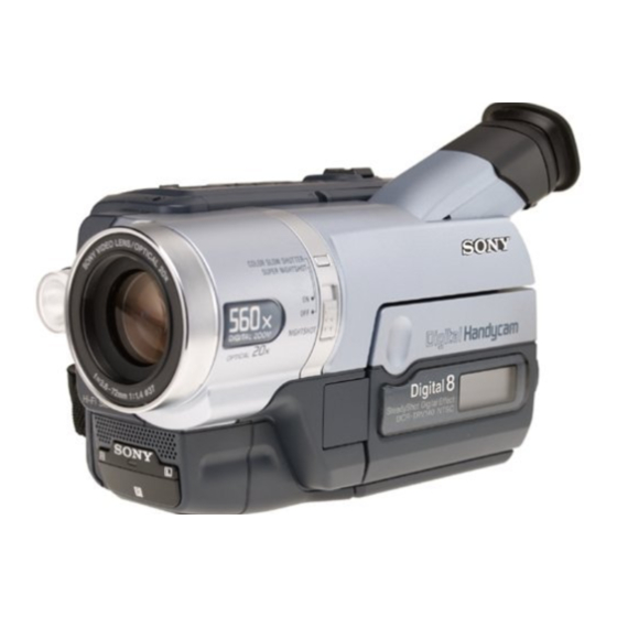
Photo: DCR-TRV140E
SPECIFICATIONS
Viewfinder
Electric Viewfinder (monochrome)
Image device
4.5 mm (1/4 type) CCD
(Charge Coupled Device)
DCR-TRV140/TRV140M:
Approx. 460 000 pixels
(Effective: Approx. 290 000 pixels)
DCR-TRV140E:
Approx. 540 000 pixels
(Effective: Approx. 350 000 pixels)
Lens
Combined power zoom lens
Filter diameter 37 mm (1 7/16 in.)
20× (Optical), 560× (Digital)
Focal length
3.6 - 72 mm (5/32 - 2 7/8 in.)
When converted to a 35 mm
still camera
41 - 820 mm (1 5/8 - 32 3/8 in.)
Colour temperature
Auto
Minimum illumination
1 lx (lux) (F 1.4)
0 lx (lux) (in the NightShot mode)*
* Objects unable to be seen due to
the dark can be shot with infrared
lighting.
DIGITAL VIDEO CAMERA RECORDER
For MECHANISM ADJUSTMENT, refer to the "8mm
Video MECHANICAL ADJUSTMENT MANUAL
M2000 MECHANISM " (9-929-861-11).
Input/output
connectors
S video output
DCR-TRV140/TRV140M:
4-pin mini DIN
Luminance signal: 1 Vp-p,
75 Ω (ohms), unbalanced
Chrominance signal: 0.286 Vp-p,
75 Ω (ohms), unbalanced
DCR-TRV140E:
4-pin mini DIN
Luminance signal: 1 Vp-p,
75 Ω (ohms), unbalanced
Chrominance signal: 0.3 Vp-p,
75 Ω (ohms), unbalanced
Audio/Video output
AV MINIJACK, 1 Vp-p, 75 Ω
(ohms), unbalanced, sync negative
327 mV, (at output impedance more
than 47 kΩ (kilohms))
Output impedance with less than
2.2 kΩ (kilohms)/Stereo minijack
(ø 3.5 mm)
DCR-TRV140/TRV140E:
E, HK, AUS, CH, JE/TRV140M
DV input/output
4-pin connector
RMT-814
US Model
DCR-TRV140/TRV140M
Canadian Model
DCR-TRV140
AEP Model
UK Model
East European Model
North European Model
Russian Model
DCR-TRV140E
E Model
Hong Kong Model
DCR-TRV140/TRV140E
Brazilian Model
DCR-TRV140
Australian Model
Chinese Model
DCR-TRV140E
Tourist Model
DCR-TRV140/TRV140E
IX
DCR-TRV140E:
AEP, UK, EE, NE, RU
DV output
4-pin connector
USB jack
Mini-B
LCD screen
Picture
6.2 cm (2.5 type)
50.3 × 37.4 mm
(2 × 1 1/2 in.)
Total dot number
61 600 (280 × 220)
General
Power requirements
7.2 V (battery pack)
8.4 V (AC power adaptor)
Average power consumption
(when using the battery pack)
During camera recording using
LCD
3.5 W
Viewfinder
2.8 W
– Continued on next page –
Advertisement
Table of Contents

Related Manuals for Sony DCR-TRV140


Summary of Contents for Sony DCR-TRV140
- Page 1 Chinese Model DCR-TRV140E Tourist Model M2000 MECHANISM Photo: DCR-TRV140E DCR-TRV140/TRV140E NTSC MODEL : DCR-TRV140/TRV140M For MECHANISM ADJUSTMENT, refer to the “8mm PAL MODEL : DCR-TRV140E Video MECHANICAL ADJUSTMENT MANUAL M2000 MECHANISM ” (9-929-861-11). When the machine needs to be repaired, please refer to page 7 to discriminate the type of LCD.
- Page 2 SONY PARTS WHOSE PART NUMBERS APPEAR AS DE FONCTIONNEMENT. NE REMPLACER CES COM- SHOWN IN THIS MANUAL OR IN SUPPLEMENTS PUB- POSANTS QUE PAR DES PIÈCES SONY DONT LES LISHED BY SONY. NUMÉROS SONT DONNÉS DANS CE MANUEL OU DANS LES SUPPLÉMENTS PUBLIÉS PAR SONY.
- Page 3 DCR-TRV140/TRV140E/TRV140M Supplied accessories RMT-814 6 Shoulder strap (1) 1 Wireless Remote Commander (1) 7 Lens cap (1) 2 AC-L10A/L10B/L10C AC power adaptor (1) Power cord (1) 8 USB Cable (1) 3 NP-FM30 battery pack (1) 9 CD-ROM (SPVD-008 USB Driver) (1) 4 R6 (Size AA) battery for Remote q;...
-
Page 4: Table Of Contents
DCR-TRV140/TRV140E/TRV140M TABLE OF CONTENTS Section Title Page Section Title Page SERVICE NOTE ..............6 2-4. Cabinet (L) Assembly ............ 2-4 2-5. Cassette Lid Assembly ..........2-4 2-6. Cabinet (R) Assembly ........... 2-6 Power Supply During Repairs ........6 2-7. EVF Block ..............2-6 To Take Out a Cassette When Not Eject 2-8. - Page 5 DCR-TRV140/TRV140E/TRV140M Section Title Page Section Title Page VF-150 Printed Wiring Board ........4-60 5-3. Video Section Adjustment ..........5-34 VF-150 Schematic Diagram .......... 4-61 3-1. Preparations Before Adjustments ......5-34 CF-2000 Schematic Diagram ........4-63 3-1-1. Equipment to Required ..........5-34 4-3.
-
Page 6: Service Note
DCR-TRV140/TRV140E/TRV140M Ver 1.1 2003. 06 SERVICE NOTE POWER SUPPLY DURING REPAIRS In this unit, about 10 seconds after power is supplied (8.4 V) to the battery terminal the power is shut off so that the unit cannot oper- ate. This following two methods are available to prevent this. Take note of which to use during repairs. -
Page 7: Note For Repair
DCR-TRV140/TRV140E/TRV140M NOTE FOR REPAIR When remove a connector, don’t pull at wire of connector. It is possible that a wire is snapped. Make sure that the flat cable and flexible board are not cracked of bent at the terminal. Do not insert the cable insufficiently nor crookedly. -
Page 8: Self-Diagnosis Function
DCR-TRV140/TRV140E/TRV140M SELF-DIAGNOSIS FUNCTION Self-diagnosis Function Self-diagnosis Display When problems occur while the unit is operating, the counter of When problems occur while the unit is operating, the self-diagno- the viewfinder or Display window shows a 4-digit display consist- sis function starts working, and displays on the viewfinder or Dis- ing of an alphabet and numbers, which blinks at 3.2 Hz. -
Page 9: Self-Diagnosis Code Table
DCR-TRV140/TRV140E/TRV140M Self-diagnosis Code Table Self-diagnosis Code Block Detailed Symptom/State Correction Function Code Non-standard battery is used. Use the InfoLITHIUM battery. Condensation. Remove the cassette, and insert it again after one hour. Video head is dirty. Clean with the optional cleaning cassette. - Page 10 DCR-TRV140/TRV140E/TRV140M Self-diagnosis Code Block Detailed Symptom/State Correction Function Code EEPROM data error Initialize page data (EEPROM) Inspect the lens block focus reset sensor (Pin qs of CN1551 of Difficult to adjust focus VC-273 board) when focusing is performed when the control dial (Cannot initialize focus.)
-
Page 11: General
This section is extracted from DCR- GENERAL TRV140E instruction manual. Checking supplied English Welcome! accessories Congratulations on your purchase of this Sony Make sure that the following accessories are Digital Handycam camcorder/Handycam supplied with your camcorder. Vision . With your Digital Handycam/ Handycam Vision , you can capture life’s... -
Page 12: Using This Manual
DCR-TRV140/TRV140E/TRV140M English — Getting started — Using this manual Using this manual Types of differences The instructions in this manual are for the five CCD- DCR- Model name models listed in the table below (p. 15). Before TRV107E TRV108E TRV208E... - Page 13 DCR-TRV140/TRV140E/TRV140M Step 1 Preparing the power Step 1 Preparing the power supply supply After charging the battery pack Charging the battery pack Disconnect the AC power adaptor from the DC IN jack on your camcorder. Use the battery pack after charging it for your camcorder.
-
Page 14: Step 2 Setting The Data And Time
•Place the AC power adaptor near the wall series battery packs have the mark. socket. While using the AC power adaptor, if “InfoLITHIUM” is a trademark of Sony any trouble occurs with this unit, disconnect the Corporation. plug from the wall socket as soon as possible to cut off the power. -
Page 15: Step 3 Inserting A Cassette
DCR-TRV140/TRV140E/TRV140M Step 3 Inserting a cassette Step 3 Inserting a cassette We recommend using Hi8 /Digital8 Notes video cassettes.* •Do not press the cassette compartment down. When you want to record in the Hi8 system, use Doing so may cause a malfunction. - Page 16 DCR-TRV140/TRV140E/TRV140M Recording a picture Recording a picture To set the counter to 0:00:00 (CCD-TRV107E/ Indicators in the mirror mode •The STBY indicator appears as Xz and REC TRV108E/TRV208E/TRV408E only) as z. Some of the other indicators appear Press COUNTER RESET (p. 195).
- Page 17 DCR-TRV140/TRV140E/TRV140M Recording a picture Recording a picture Indicators displayed in the Remaining battery time indicator The remaining battery time indicator indicates recording mode the approximate recording time. The indicator may not be correct, depending on the conditions The indicators are not recorded on tape.
-
Page 18: Checking The Recording - End Search
DCR-TRV140/TRV140E/TRV140M Recording a picture Recording a picture Using the Colour Slow Shutter While using the NightShot function, you (DCR-TRV140E only) cannot use the following functions: – Exposure The Colour Slow Shutter enables you to record – PROGRAM AE colour images in a dark place. -
Page 19: Playing Back A Tape
DCR-TRV140/TRV140E/TRV140M — Playback – Basics — Playing back a tape Playing back a tape When monitoring on the LCD screen You can turn the LCD panel over and move it You can playback tapes recorded in the back to the camcorder body with the LCD screen Digital8 system.*... -
Page 20: Viewing The Recording On Tv
DCR-TRV140/TRV140E/TRV140M Playing back a tape Playing back a tape To view the picture at slow speed Various playback modes (slow playback) (CCD-TRV107E/ TRV208E/TRV408E, DCR-TRV140E only) To operate video control buttons, set the Press y on the Remote Commander during POWER switch to PLAYER. -
Page 21: Recording A Still Image On A Tape - Tape Photo Recording
DCR-TRV140/TRV140E/TRV140M Viewing the recording on TV Viewing the recording on TV – DCR-TRV140E To connect to a TV without Video/ Audio input jacks (CCD-TRV107E/ TRV108E/TRV208E/TRV408E only) Yellow/ Use a PAL system RFU adaptor (optional). Refer to the operating instructions of your TV White/ and the RFU adaptor. -
Page 22: Using The Wide Mode
DCR-TRV140/TRV140E/TRV140M Using the wide mode Using the wide mode – DCR-TRV140E You can record a 16:9 wide picture to watch on the 16:9 wide-screen TV (16:9WIDE). Black bands appear on the LCD screen during CINEMA CINEMA recording in 16:9WIDE mode [a]. The pictures... -
Page 23: Using Special Effects - Picture Effect
DCR-TRV140/TRV140E/TRV140M Using the fader function Using the fader function MONOTONE Note (DCR-TRV140E only) When fading in, the picture gradually changes You cannot use the following functions while from black-and-white to colour. using the fader function. Also, you cannot When fading out, the picture gradually changes use the fader function while using the following from colour to black-and-white. -
Page 24: Using Special Effects - Digital Effect
DCR-TRV140/TRV140E/TRV140M Using special effects Using special effects – Digital effect – Digital effect (1) In CAMERA mode, select D EFFECT in the menu settings (p. 136). – DCR-TRV140E only – (2) Select the desired digital effect mode in the You can add special effects to recorded images menu settings, then press the SEL/PUSH using the various digital functions. -
Page 25: Adjusting The Exposure Manually
DCR-TRV140/TRV140E/TRV140M Using the PROGRAM AE function Using the PROGRAM AE function (1) In CAMERA mode, select PROGRAM AE in Notes in the menu settings (p. 136). •In the spotlight, sports lesson and beach & ski (2) Select the desired PROGRAM AE mode in the modes, you cannot take close-ups. -
Page 26: Interval Recording
DCR-TRV140/TRV140E/TRV140M Interval recording Focusing manually – DCR-TRV140E only To focus precisely You can make a time-lapse recording by setting Adjust the zoom by first focusing at the “T” the camcorder to automatically record and (telephoto) position and then shooting at the “W”... -
Page 27: Frame By Frame Recording - Cut Recording
DCR-TRV140/TRV140E/TRV140M Frame by frame recording Frame by frame recording – Cut recording – – Cut recording To cancel the cut recording Set FRAME REC to OFF in the menu settings. – DCR-TRV140E only You can make a recording with a stop-motion Notes on cut recording animated effect using cut recording. -
Page 28: Making Your Own Titles
DCR-TRV140/TRV140E/TRV140M Making your own titles Superimposing a title To use the custom title You can make up to two titles and store them in If you want to use the custom title, select your camcorder. Each title can have up to 20 step 2. -
Page 29: Playing Back A Tape With Picture Effects
Using the built-in light with picture effects CAUTION – DCR-TRV140E only •When replacing the bulb, use only the Sony During playback, you can process a scene using XB-3D halogen lamp (optional) to reduce the the picture effect functions: NEG.ART, SEPIA, risk of fire. -
Page 30: Playing Back A Tape With Digital Effects
DCR-TRV140/TRV140E/TRV140M Playing back a tape Playing back a tape with digital with digital effects effects – DCR-TRV140E only To cancel the digital effect function During playback, you can process a scene using Set D EFFECT to OFF in the menu settings. -
Page 31: Quickly Locating A Scene Using The Zero Set Memory Function
DCR-TRV140/TRV140E/TRV140M Quickly locating a Quickly locating a scene using scene using the zero the zero set memory function set memory function Notes •When you press ZERO SET MEMORY on the – DCR-TRV140E only Remote Commander before rewinding the tape, Your camcorder goes forwards or backwards to the zero set memory function is cancelled. -
Page 32: Searching For A Photo - Photo Search/Photo Scan
DCR-TRV140/TRV140E/TRV140M Searching for a photo Searching for a photo – Photo search/Photo – Photo search/Photo scan scan Scanning photo – DCR-TRV140E only (1) Set the POWER switch to PLAYER. You can search for the still image recorded on (2) Press SEARCH MODE on the Remote tape (Photo search). -
Page 33: Dubbing A Tape Easily - Easy Dubbing
DCR-TRV140/TRV140E/TRV140M Dubbing a tape Dubbing a tape When you have finished dubbing a Using the i.LINK cable (DV connecting tape cable) (DCR-TRV140E only) Press x on both your camcorder and the VCR. Simply connect the i.LINK cable (DV connecting cable) (optional) to... - Page 34 DCR-TRV140/TRV140E/TRV140M Dubbing a tape easily Dubbing a tape easily – Easy Dubbing – Easy Dubbing Step 2: Setting the VCR to operate Buttons for cancelling recording pause on the with your camcorder The buttons vary depending on your VCR. To...
- Page 35 DCR-TRV140/TRV140E/TRV140M Dubbing a tape easily Dubbing a tape easily – Easy Dubbing – Easy Dubbing When the VCR does not operate correctly E A S Y D U B B I N G E A S Y D U B B I N G •After checking the code in “About the IR...
-
Page 36: Dubbing Only Desired Scenes - Digital Program Editing
DCR-TRV140/TRV140E/TRV140M Dubbing only desired Dubbing only desired scenes scenes – Digital program editing – – – Digital program editing Step 2: Setting the VCR to – DCR-TRV140E only – operate with the A/V connecting cable You can duplicate selected scenes (programmes) - Page 37 DCR-TRV140/TRV140E/TRV140M Dubbing only desired scenes Dubbing only desired scenes – Digital program editing – Digital program editing – – (3) Setting your camcorder and the (4) Confirming the VCR operation 1 Insert a recordable tape into the VCR, VCR to face each other then set to recording pause.
- Page 38 DCR-TRV140/TRV140E/TRV140M Dubbing only desired scenes Dubbing only desired scenes – Digital program editing – Digital program editing – – (15) (15) Turn the SEL/PUSH EXEC dial to select Operation 1: Making the RETURN, then press the dial. programme (1) Insert the tape for playback into your camcorder, and insert a tape for recording into the VCR.
-
Page 39: Viewing Images Using Your Computer - Usb Streaming (Windows Users Only)
Sony” (p. 129). computer at the same time or when using a •Capturing images with “PIXELA ImageMixer hub. • Ver.1.0 for Sony” (p. 130). • •Depending on the type of USB equipment used • simultaneously, some equipment may not Recommended computer operate. - Page 40 Install “PIXELA ImageMixer Ver.1.0 for Sony” to For Windows 2000 Professional users your computer. “PIXELA ImageMixer Ver.1.0 Log in with permission of Power Users or for Sony” is contained on the CD-ROM supplied Administrator. with your camcorder. You can view video images For Windows XP users easily on your camcorder, using your computer Log in with permission of Administrator.
-
Page 41: Changing The Menu Settings
If you have any questions about “PIXELA ImageMixer Ver.1.0 for Sony” For details, see “Selecting the mode setting of each item”(p. 136). ImageMixer Ver.1.0 for Sony is a trademark of PIXELA corporation. Refer to the information web site at: “http://www.imagemixer.com”. Notes on using your computer... - Page 42 DCR-TRV140/TRV140E/TRV140M Changing the menu settings Changing the menu settings Menu items are displayed as the following MA NU A L S E T DCR-TRV140E icons: P ROGR AM A E P E F F E C T MANUAL SET CAMERA...
- Page 43 When you play back the tape on other camcorders or VCRs, noise may occur in images or sound. •When you record in the LP mode, we recommend using a Sony video cassette so that you can get the most out of your camcorder.
-
Page 44: Types Of Trouble And Their Solutions
To set the clock to the local time. CAMERA problem. If the problem persists, disconnect the power source and contact your Sony dealer or local Turn the SEL/PUSH EXEC dial to set the time authorised Sony service facility. If “C:ss:ss” appears on the screen, the self-diagnosis display difference. -
Page 45: Self-Diagnosis Display
Install it properly. Five-digit display Cause and/or Corrective Actions • Something is wrong with the battery pack. c Contact your Sony dealer or local authorised Sony service C:04:ss • You are using a battery pack that is not an “InfoLITHIUM” facility. -
Page 46: Warning Indicators And Messages
Slow flashing: • CLEANING CASSETTE* The video heads are dirty. (p. 181) – You need to clean the heads using the Sony V8-25CLD cleaning cassette (optional). (p. 180) – CCD-TRV107E/TRV108E/TRV208E/TRV408E only • Q TAPE END* The tape has reached the end. -
Page 47: Abut The "Infolithium" Battery Pack
DCR-TRV140/TRV140E/TRV140M About video cassettes About video cassettes – CCD-TRV107E/TRV108E/TRV208E/ – Playing back an NTSC-recorded tape TRV408E only You can play back tapes recorded in the NTSC video system using the SP mode. However, note that the following will occur Selecting the cassette type during playback of an NTSC-recorded tape. -
Page 48: About I.link
IEEE 1394 data personal computer. transport bus proposed by SONY, and is a For details on precautions when connecting this trademark approved by many corporations. - Page 49 If this is the case, they must be replaced with new heads. Contact your Sony dealer or local authorised Sony service facility. [a]: Slightly dirty [a]:...
- Page 50 If any problem occurs, unplug your camcorder •Keep the battery pack away from fire. and contact your nearest Sony dealer. •Never expose the battery pack to temperatures above 60°C (140°F), such as in a car parked in the sun or under direct sunlight.
-
Page 51: Identifying The Parts And Controls
DCR-TRV140/TRV140E/TRV140M — Quick Reference — Identifying the parts Identifying the parts and controls and controls Camcorder qd Video control buttons (p. 43, 47) x STOP (stop) m REW (rewind) N PLAY (playback)* M FF (fastforward) X PAUSE (pause) 1 Eyecup qf LIGHT button (p. - Page 52 VTR 2. The commander modes 1, 2 and 3 are used to distinguish your camcorder from other Sony VCRs to avoid unintentional operations. If you use another Sony VCR in the commander 1 Recording mode indicator (p. 140)/ mode VTR 2, we recommend changing the Mirror mode indicator (p.
- Page 53 DCR-TRV140/TRV140E/TRV140M Identifying the parts and controls qs Manual focusing indicator (p. 70) qd Built-in light indicator (p. 82) qf STBY/REC indicator (p. 29)/ Video control mode indicator (p. 47) qg Tape counter indicator (p. 35)/ Time code indicator (p. 35)* Self-diagnosis display indicator (p.
-
Page 54: Disassembly
DCR-TRV140/TRV140E/TRV140M SECTION 2 DISASSEMBLY • This set can be disassembled in the order shown below. 2-1. LCD ASSEMBLY, PD-156 BOARD LCD SERVICE POSITION (page 2-2) (page 2-2) 2-2. VF LENS ASSEMBLY, VF-150 BOARD EVF SERVICE POSITION (page 2-3) (page 2-3) 2-3. -
Page 55: Lcd Assembly, Pd-156 Board
DCR-TRV140/TRV140E/TRV140M Ver 1.1 2003. 06 Note: Follow the disassembly procedure in the numerical order given. 2-1. LCD ASSEMBLY, PD-156 BOARD qf Claw qd Claw 4 P cabinet (C) qg Indication LCD block assembly 7 Two tapping qa PD-156 board screws... -
Page 56: Vf Lens Assembly, Vf-150 Board
DCR-TRV140/TRV140E/TRV140M Ver 1.1 2003. 06 2-2. VF LENS ASSEMBLY, VF-150 BOARD 4 Claw 5 EVF cabinet (upper) 8 VF-150 board 7 FP-401 flexible board 6 Flexible board (CN2001, 7701) (CN2002) 7 VF lens assembly 3 EVF cabinet (rear) assembly 1 Pull out the EVF block. -
Page 57: Video Light And Front Panel Assembly
DCR-TRV140/TRV140E/TRV140M 2-3. VIDEO LIGHT AND FRONT PANEL ASSEMBLY 3 Two screws (M2) 4 Screw (M2) 2 Jack cover 5 Two screws (M2) Wire 8 FP-418 flexible board Video light Hole (CN752) 6 Two claws 1 Remove the video light while pushing the hole Note: Remove it while under the video light using a wire. - Page 58 DCR-TRV140/TRV140E/TRV140M Ver 1.1 2003. 06 [MECHANISM DECK SERVICE POSITION] Note: Use the parts only which can be removed easily from outside of the mechanism deck. AC power AC IN adaptor Mechanism deck CPC jig connector (J-6082-539-A) Conductor side Info lithium battery...
-
Page 59: Cabinet (R) Assembly
DCR-TRV140/TRV140E/TRV140M 2-6. CABINET (R) ASSEMBLY 8 USB lid 6 Control switch block (CN1007) 1 Screw 2 Screw (M2) (M2) 7 Screw (tripod) 5 Harness (PD-115) (CN1003) 4 Cabinet (R) assembly 3 Three screws (M2) 2-7. EVF BLOCK 2-8. BATTERY PANEL BLOCK... -
Page 60: Lens Assembly
DCR-TRV140/TRV140E/TRV140M Ver 1.1 2003. 06 2-9. LENS ASSEMBLY 1 Lens flexible board (CN1551) 2 FP-400 flexible board (CN1501) 4 Screw (P M2) 7 Two tapping screws 8 Lens frame 3 Two screws 6 Lens block (P M2) 9 Lens assembly... -
Page 61: Board
DCR-TRV140/TRV140E/TRV140M 2-10. VC-273 BOARD 8 Control switch block (CN1008) 5 Screw (P M2) 9 FP-398 flexible board (CN1001) 7 VC-273 board 2 MD frame (B) 6 Claw 1 Two screws (P M2) 4 Four flexible boards 3 Connector (CN3101, 4402, 4403, 4404) (CN4401) 2-11. -
Page 62: Service Position To Check The Vtr Section
DCR-TRV140/TRV140E/TRV140M Ver 1.1 2003. 06 [SERVICE POSITION TO CHECK THE VTR SECTION] Setting the “Forced VTR Power ON” mode (VTR mode) Exiting the “Forced Power ON” mode 1) Select page: 0, address: 01, and set data: 01. 1) Select page: 0, address: 01, and set data: 01. - Page 63 DCR-TRV140/TRV140E/TRV140M 2-13. CIRCUIT BOARDS LOCATION LB-073 VC-273 VF-150 PD-156 CD-353 SI-033 Board Name Function CD-353 CCD IMAGER LB-073 EVF BACK LIGHT PD-156 RGB DRIVER, TIMING GENERATTOR, BACK LIGHT SI-033 STEADY SHOT, MIC CAMERA PROCESS, FOCUS/ZOOM DRIVE, EVR, DV SIGNAL PROCESS,...
-
Page 64: Control Switch Block (Fk-2000)
DCR-TRV140/TRV140E/TRV140M 2-14. FLEXIBLE BOARDS LOCATION CONTROL SWITCH BLOCK (SS-2000) FP-401 FP-400 FP-399 FP-398 FP-394 CONTROL SWITCH BLOCK (CF-2000) FP-418 2-11 E 2-11... -
Page 65: Block Diagrams
DCR-TRV140/TRV140E/TRV140M SECTION 3 BLOCK DIAGRAMS 3-1. OVERALL BLOCK DIAGRAM (1/5) CD-353 BOARD VC-273 BOARD (1/4) LENS ASSY IC1502 SPCK S/H, AGC, A/D CONVERTER SPCK(IC1501) (SEE PAGE 4-15) IRIS IC2001 Q2001 CN1501 IC2201 CCD OUT IMAGER BUFFER CAMERA ZOOM MOTOR FOCUS MOTOR IRIS ı... -
Page 66: Overall Block Diagram (2/5)
DCR-TRV140/TRV140E/TRV140M 3-2. OVERALL BLOCK DIAGRAM (2/5) CN101 TRV140/TRV140E FP-398 FLEXIBLE FP-399 FLEXIBLE VC-273 BOARD (2/4) : E, HK, AUS, CH, JE (2/3) (SEE PAGE 4-40) /TRV140M (SEE PAGE 4-41) CN1001 X3301 TPA+, –, (2/3) 24.576MHz DV IN/OUT TPB+, – X801 ı... -
Page 67: Overall Block Diagram (3/5)
DCR-TRV140/TRV140E/TRV140M 3-3. OVERALL BLOCK DIAGRAM (3/5) M2000 MECHA DECK VC-273 BOARD (3/4) (SEE PAGE 4-10) (SEE PAGE 4-36) (SEE PAGE 4-45) (SEE PAGE 4-33) (SEE PAGE 4-36) M901 IC1301 Q1306 CN4402 IC4401 DRUM MOTOR DRUM PWM DRUM PWM DRUM ERROR... -
Page 68: Overall Block Diagram (4/5)
DCR-TRV140/TRV140E/TRV140M 3-4. OVERALL BLOCK DIAGRAM (4/5) VC-273 BOARD (4/4) CONTROL SWITCH BLOCK (CF-2000) (2/2) (SEE PAGE 4-63) IC4803 HI CONTROL (SEE PAGE 4-30) S007 CN1007 DIAL A XCS MECHA XCS MECHA (IC4501) DIAL B DIAL A XCS VC XCS VC (IC4902) -
Page 69: Overall Block Diagram (5/5)
DCR-TRV140/TRV140E/TRV140M 3-5. OVERALL BLOCK DIAGRAM (5/5) PD-156 BOARD (2/2) PANEL ID XHD OUT R5522 1.5k : TYPE C PANEL COM CN5502 1k : TYPE S VR,VG,VB ADJUSTMENTS PANEL R LCD901 PANEL G IC5501 T5601 PANEL B VR, VG, VB ND901... -
Page 70: Power Block Diagram (1/2)
DCR-TRV140/TRV140E/TRV140M 3-6. POWER BLOCK DIAGRAM (1/2) VC-273 BOARD BT901 BATTERY BATT SIG TERMINAL CN701 BATT/XEXT SW F001 BATT UNREG INIT CHARGE ON CHARGE BATT SIG BATT SIG CONTROL BATT/XEXT SW Q701 Q702-704 FAST CHARGE BATT GND – FAST CHARGE INIT CHARGE ON... -
Page 71: Power Block Diagram (2/2)
DCR-TRV140/TRV140E/TRV140M 3-7. POWER BLOCK DIAGRAM (2/2) VC-273 BOARD CONTROL SWITCH BLOCK (SS-2000) (SEE PAGE 4-41) CAMERA CN1009 XCAM MODE SW S001 XVTR MODE SW POWER OFF (CHG) BATT SIG IC4803 BATT/XEXT SW TRV140/TRV140E : HI CONTROL TRV140E : AEP, UK,... -
Page 72: Printed Wiring Boards And Schematic Diagrams
DCR-TRV140/TRV140E/TRV140M SECTION 4 PRINTED WIRING BOARDS AND SCHEMATIC DIAGRAMS THIS NOTE IS COMMON FOR WIRING BOARDS AND SCHEMATIC DIAGRAMS (In addition to this, the necessary note is printed in each block) (For printed wiring boards) • : Uses unleaded solder. -
Page 73: Frame Schematic Diagrams
DCR-TRV140/TRV140E/TRV140M 4-1. FRAME SCHEMATIC DIAGRAMS FRAME (1/2) SCHEMATIC DIAGRAM CONTROL SWITCH BLOCK CD-353 BOARD (FK-2000) IC2001 S003,004 PHOTO LENS UNIT IMAGER S001 S013 S002 S003 S004 LIGHT EJECT RESET (PHOTO FREEZE) (PHOTO START) RV001 S005 S008 S009 S007 S006 (REC) -
Page 74: Frame (2/2) Schematic Diagram
DCR-TRV140/TRV140E/TRV140M FRAME (2/2) SCHEMATIC DIAGRAM LCD903 S002 S004 S009 S016 B/W LCD UNIT MENU FADER EXPOSURE BACK LIGHT S003 S005 S010 S013 S018 SUPER NIGHT SHOT DISPLAY END SEARCH PB ZOOM FOCUS S019 S006 S012 S015 SEL/PUSH EXEC CN004 TITLE... -
Page 75: Printed Wiring Boards And Schematic Diagram
DCR-TRV140/TRV140E/TRV140M 4-2. PRINTED WIRING BOARDS AND SCHEMATIC DIAGRAM CD-353 (CCD IMAGER) PRINTED WIRING BOARD AND SCHEMATIC DIAGRAM • See page 4-65 for waveforms. – Ref. No.: CD-353 board; 40,000 series – • For Printed Wiring Board. • :Uses unleaded solder. -
Page 76: Schematic Diagram
DCR-TRV140/TRV140E/TRV140M LS-057 (S/T REEL SENSOR), FP-228 (DEW SENSOR), FP-299 (MODE SWITCH), FP-300 (TAPE TOP), FP-302 (TAPE END), FP-301 (TAPE LED) FLEXIBLE PRINTED WIRING BOARDS AND SCHEMATIC DIAGRAM – Ref. No.: LS-057 board; 1,000 series/FP-228 board; 1,000 series/FP-299 board; 1,000 series/FP-300 board; 1,000 series/FP-302 board; 1,000 series/FP-301 board; 1,000 series –... -
Page 77: Printed Wiring Board
DCR-TRV140/TRV140E/TRV140M VC-273 (CAMERA PROCESS, FOCUS/ZOOM DRIVE, EVR, DV SIGNAL PROCESS, DV INTERFACE, DIGITAL REC/PB AMP, VIDEO OUT, HI CONTROL, CAMERA/MECHA CONTROL, MECHANISM CONTROL, DRUM/CAPSTAN MOTOR DRIVE/AUDIO PROCESS, DC IN, CHARGE, DC/DC CONVERTER) PRINTED WIRING BOARD — Ref. No. VC-273 Board; 10,000 Series —... - Page 78 DCR-TRV140/TRV140E/TRV140M 4-13 4-14 CAMERA PROCESS, FOCUS/ZOOM DRIVE, EVR, DV SIGNAL PROCESS, DV INTERFACE, DIGITAL REC/PB AMP, VIDEO OUT, HI CONTROL, CAMERA/MECHA CONTROL, MECHANISM CONTROL, DRUM/CAPSTAN MOTOR DRIVE/AUDIO PROCESS, DC IN, CHARGE, DC/DC CONVERTER VC-273...
-
Page 79: Camera Process
DCR-TRV140/TRV140E/TRV140M VC-273 (CAMERA PROCESS) SCHEMATIC DIAGRAM • See page 4-11 for VC-273 printed wiring board. • See page 4-65 for waveforms. VC-273 BOARD (1/16) REG_GND CAMERA PROCESS(CH BLOCK) CAM_-6.5V -REF.NO.:10,000 SERIES- VC-273 BOARD (16/16) CAM_12V XX MARK:NO MOUNT NO MARK:REC/PB MODE A_2.8V... -
Page 80: Camera Y/C Process
DCR-TRV140/TRV140E/TRV140M VC-273 (CAMERA Y/C PROCESS) SCHEMATIC DIAGRAM • See page 4-11 for VC-273 printed wiring board. VC-273 BOARD (2/16) CAMERA Y/C PROCESS(BIRDS+ BLOCK) -REF.NO.:10,000 SERIES- NO MARK:REC/PB MODE SPCK IFI_VD VC-273 BOARD (9/16) IFI_OE IFI_HD IFI_HD IFI_VD IFI_VD IFI_OE IFI_OE... -
Page 81: Lens Motor Drive) Schematic Diagram
DCR-TRV140/TRV140E/TRV140M VC-273 (LENS MOTOR DRIVE) SCHEMATIC DIAGRAM • See page 4-11 for VC-273 printed wiring board. VC-273 BOARD (3/16) LENS MOTOR DRIVE(LD BLOCK) -REF.NO.:10,000 SERIES- R1561 2200 XX MARK:NO MOUNT HALL_REF NO MARK:REC/PB MODE R1562 C1559 R:REC MODE 0.22u R1564... -
Page 82: Dv Signal Process) Schematic Diagram
DCR-TRV140/TRV140E/TRV140M VC-273 (DV SIGNAL PROCESS) SCHEMATIC DIAGRAM • See page 4-11 for VC-273 printed wiring board. • See page 4-65 for waveforms. VC-273 BOARD (4/16) NO MARK:REC/PB MODE R:REC MODE P:PB MODE DV SIGNAL PROCESS(JC BLOCK) -REF.NO.:10,000 SERIES- XX MARK:NO MOUNT RF_1.9V... -
Page 83: Dv Interface) Schematic Diagram
DCR-TRV140/TRV140E/TRV140M VC-273 (DV INTERFACE) SCHEMATIC DIAGRAM • See page 4-11 for VC-273 printed wiring board. SIGNAL PATH VC-273 BOARD (5/16) NO MARK:REC/PB MODE R:REC MODE VIDEO SIGNAL P:PB MODE AUDIO DV INTERFACE(JC BLOCK) SIGNAL CHROMA Y/CHROMA -REF.NO.:10,000 SERIES- XX MARK:NO MOUNT D_1.9V... -
Page 84: Digital Rec/Pb Amp) Schematic Diagram
DCR-TRV140/TRV140E/TRV140M VC-273 (DIGITAL REC/PB AMP) SCHEMATIC DIAGRAM • See page 4-11 for VC-273 printed wiring board. • See page 4-65 for waveforms. VC-273 BOARD (6/16) DIGITAL REC/PB AMP(RF BLOCK) -REF.NO.:10,000 SERIES- XX MARK:NO MOUNT Q3111 NO MARK:REC/PB MODE 2PA1774RJ-115 :TRV140E R:REC MODE 2SB1462J-QR(K8).S0... -
Page 85: Video Out) Schematic Diagram
DCR-TRV140/TRV140E/TRV140M VC-273 (VIDEO OUT) SCHEMATIC DIAGRAM • See page 4-11 for VC-273 printed wiring board. • See page 4-65 for waveforms. VC-273 BOARD (7/16) VIDEO OUT(IO BLOCK) -REF.NO.:10,000 SERIES- NO MARK:REC/PB MODE A_4.75V L3703 10uH C3714 VC-273 BOARD (16/16) 6.3V... - Page 86 DCR-TRV140/TRV140E/TRV140M VC-273 (HI CONTROL) SCHEMATIC DIAGRAM • See page 4-11 for VC-273 printed wiring board. • See page 4-65 for waveforms. VC-273 BOARD (8/16) HI CONTROL(HI BLOCK) -REF.NO.:10,000 SERIES- XX MARK:NO MOUNT VC-273 VC-273 VC-273 BOARD BOARD BOARD NO MARK:REC/PB MODE...
-
Page 87: Camera/Mecha Control) Schematic Diagram
DCR-TRV140/TRV140E/TRV140M VC-273 (CAMERA/MECHA CONTROL) SCHEMATIC DIAGRAM • See page 4-11 for VC-273 printed wiring board. • See page 4-65 for waveforms. VC-273 BOARD (9/16) VC-273 BOARD (1/16,2/16) VC-273 BOARD (3/16) CAMERA/MECHA CONTROL VC-273 VC-273 BOARD BOARD (VC,AA,SE BLOCK) (14/16) (5/16) -
Page 88: Mechanism Control) Schematic Diagram
DCR-TRV140/TRV140E/TRV140M VC-273 (MECHANISM CONTROL) SCHEMATIC DIAGRAM • See page 4-11 for VC-273 printed wiring board. • See page 4-65 for waveforms. VC-273 BOARD (10/16) MECHANISM CONTROL(MC BLOCK) REG_GND -REF.NO.:10,000 SERIES- VC-273 BOARD (16/16) XX MARK:NO MOUNT D_2.8V NO MARK:REC/PB MODE... -
Page 89: Drum/Capstan Motor Drive) Schematic Diagram
DCR-TRV140/TRV140E/TRV140M VC-273 (DRUM/CAPSTAN MOTOR DRIVE) SCHEMATIC DIAGRAM • See page 4-11 for VC-273 printed wiring board. • See page 4-65 for waveforms. VC-273 BOARD (15/16) VC-273 BOARD (11/16) VTR_UNREG CAP_ERROR DRUM/CAPSTAN MOTOR DRIVE(MD BLOCK) DRUM_ERROR CAP_VS VC-273 BOARD (16/16) -REF.NO.:10,000 SERIES-... -
Page 90: Audio Process) Schematic Diagram
DCR-TRV140/TRV140E/TRV140M VC-273 (AUDIO PROCESS) SCHEMATIC DIAGRAM • See page 4-11 for VC-273 printed wiring board. VC-273 BOARD (12/16) C5440 C5439 AUDIO PROCESS(AU BLOCK) 0.01u 0.001u C5441 -REF.NO.:10,000 SERIES- C5437 R5429 0.001u 0.01u 1500 XX MARK:NO MOUNT MIC_L R5432 NO MARK:REC/PB MODE... -
Page 91: Usb I/F), Fp-399 Schematic Diagram
DCR-TRV140/TRV140E/TRV140M VC-273 (USB I/F), FP-399 (USB) SCHEMATIC DIAGRAM • See page 4-11 for VC-273 printed wiring board. • See page 4-65 for waveform. VC-273 BOARD (13/16) NO MARK:REC/PB MODE R:REC MODE P:PB MODE USB I/F(USB BLOCK) -REF.NO.:10,000 SERIES- XX MARK:NO MOUNT... - Page 92 DCR-TRV140/TRV140E/TRV140M FK-2000, SS-2000 (CONTROL SWITCH BLOCK), VC-273 (CONNECTOR), FP-398 (VIDEO LIGHT, S VIDEO) SCHEMATIC DIAGRAM • See page 4-43 for FP-398 flexible printed wiring board. VC-273 BOARD (14/16) CN1005 CONNECTOR(CN BLOCK) -REF.NO.:10,000 SERIES- EVF_B XX MARK:NO MOUNT EVF_R NO MARK:REC/PB MODE...
-
Page 93: Flexible Printed Wiring Board
DCR-TRV140/TRV140E/TRV140M FP-398 (VIDEO LIGHT, S VIDEO) VC-273 (DC IN, CHARGE) SCHEMATIC DIAGRAM FLEXIBLE PRINTED WIRING BOARD • See page 4-11 for VC-273 printed wiring board. • See page 4-41 for FP-398 schematic diagram. VC-273 BOARD (15/16) DC IN,CHARGE(FU BLOCK) FP-398 FLEXIBLE -REF.NO.:10,000 SERIES-... -
Page 94: Dc/Dc Converter) Schematic Diagram
DCR-TRV140/TRV140E/TRV140M VC-273 (DC/DC CONVERTER) SCHEMATIC DIAGRAM • See page 4-11 for VC-273 printed wiring board. VC-273 BOARD (16/16) NO MARK:REC/PB MODE R:REC MODE P:PB MODE VC-273 VC-273 BOARD VC-273 BOARD VC-273 BOARD DC/DC CONVERTER(DD BLOCK) BOARD (3/16) (11/16) (14/16) (5/16) -
Page 95: Printed Wiring Board
DCR-TRV140/TRV140E/TRV140M • For Printed Wiring Board. • SI-033 board is six-layer print board. However, the patterns of layers 2 to 5 have not been included in the diagram. SI-033 (STEADYSHOT, MIC) PRINTED WIRING BOARD • There are a few cases that the part isn't mounted in this model is printed on this diagram. - Page 96 DCR-TRV140/TRV140E/TRV140M SI-033 (STEADYSHOT, MIC) SCHEMATIC DIAGRAM SI-033 BOARD STEADYSHOT,MIC -REF.NO.:1,000 SERIES- XX MARK:NO MOUNT NO MARK:REC/PB MODE FB754 CL752 D751 Vref 1 SEIDEN MA111-(K8).S0 LND750 PITCH SENSOR SE750 C752 LIA1 CL753 MIC901 CN750 CL756 INT_MIC_L FB755 L-CH MIC_GND CL754 INT_MIC_R...
-
Page 97: Printed Wiring Board
DCR-TRV140/TRV140E/TRV140M PD-156 (RGB DRIVER, TIMING GENERATOR, BACK LIGHT) PRINTED WIRING BOARD • For Printed Wiring Board. • :Uses unleaded solder. – Ref. No.: PD-156 flexible board; 30,000 – • PD-156 board is six-layer print board. However, the patterns of layers 2 to 5 have not been included in the diagram. - Page 98 DCR-TRV140/TRV140E/TRV140M 4-54 RGB DRIVER, TIMING GENERATOR, BACK LIGHT 4-53 PD-156...
- Page 99 DCR-TRV140/TRV140E/TRV140M PR-10000 (CONTROL SWITCH BLOCK), PD-156 (RGB DRIVER, TIMING GENERATOR) SCHEMATIC DIAGRAM • See page 4-51 for PD-156 printed wiring board. • See page 4-67 for waveforms. PD-156 BOARD (1/2) FB5502 RGB DRIVE,TIMING GENERATOR FB5503 -REF.NO.:30,000 SERIES- XX MARK:NO MOUNT...
-
Page 100: Lcd Driver, Back Light Drive) Schematic Diagram
DCR-TRV140/TRV140E/TRV140M PD-156 (LCD DRIVER, BACK LIGHT DRIVE) SCHEMATIC DIAGRAM • See page 4-51 for PD-156 printed wiring board. • See page 4-67 for waveform. PD-156 BOARD (2/2) LCD DRIVE,BACKLIGHT DRIVE -REF.NO.:30,000 SERIES- XX MARK:NO MOUNT NO MARK:REC/PB MODE L5602 L5601 4.7uH... -
Page 101: Printed Wiring Board
DCR-TRV140/TRV140E/TRV140M LB-073 (EVF BACK LIGHT) PRITNED WIRING BOARD AND SCHEMATIC DIAGRAM VF-150 (EVF DRIVE) PRINTED WIRING BOARD • For Printed Wiring Board. • :Uses unleaded solder. – Ref. No.: LB-073 board; 20,000 series – – Ref. No.: VF-150 board; 20,000 series –... - Page 102 DCR-TRV140/TRV140E/TRV140M VF-150 (EVF DRIVE) SCHEMATIC DIAGRAM • See page 4-67 for waveforms. VF-150 BOARD EVF DRIVE CN2001 FB2002 -REF.NO.:20,000 SERIES- C2011 C2013 3.3u XX MARK:NO MOUNT 0.01u EVF_B NO MARK:REC/PB MODE EVF_R R2004 EVF_G/BW_Y 13.1 PANEL_XVD VC-273 BOARD (14/16) PANEL_XHD...
- Page 103 DCR-TRV140/TRV140E/TRV140M CF-2000 (CONTROL SWITCH BLOCK) SCHEMATIC DIAGRAM CONTROL SWITCH BLOCK (CF-2000) XX MARK:NO MOUNT CONTROL SWITCH BLOCK(CF-2000) is replaced as a block. so its PRINTED WIRING BOARD is omitted. CN002 S007 SEL/PUSH EXEC REG_GND (SEL) W001 XHI_RESET SP+(BEEP) KEY_AD4 BT001 D_2.8V...
-
Page 104: Waveforms
DCR-TRV140/TRV140E/TRV140M 4-3. WAVEFORMS CD-353 BOARD VC-273 BOARD 7.2 Vp-p 3.3 Vp-p 3.8 Vp-p 1.8 Vp-p 3.2 Vp-p 27 MHz 63.6 µsec 40.6 nsec 2.2 msec IC2001 1, 2 REC/PB IC1501 5 REC/PB IC3301 <zc. REC/PB IC3701 qf,qg S JACK IN IC4401 tj, tl, ya REC/PB 7.2 Vp-p... -
Page 105: Parts Location
DCR-TRV140/TRV140E/TRV140M PD-156 BOARD VF-150 BOARD 4-4. PARTS LOCATION no mark : SIDE A 320 mVp-p * mark : SIDE B 470 mVp-p 2.8 Vp-p VC-273 BOARD 6MHz C5432 IC2202 C703 C1504 C3134 C4417 Q1302 IC5501 rk REC/PB IC5502 wh REC/PB... - Page 106 DCR-TRV140/TRV140E/TRV140M SI-033 BOARD PD-156 BOARD R5515 R1304 R3108 R4425 RB4502 C751 C5501 R3110 C752 C5504 R5516 R1305 R4426 RB4503 R3111 R5517 R1306 R4427 RB4800 C5505 R5518 R1307 R3113 R4428 RB4802 CN750 C5506 R5519 R1309 R3114 R4429 RB4803 CN751 C5507 R3115...
-
Page 107: Adjustments
DCR-TRV140/TRV140E/TRV140M SECTION 5 ADJUSTMENTS Before starting adjustment EVR Data Re-writing Procedure When Replacing Board The data that is stored in the repair board, is not necessarily correct. Perform either procedure 1 or procedure 2 or procedure 3 when replacing board. -
Page 108: Adjusting Items When Replacing Main Parts And Boards
DCR-TRV140/TRV140E/TRV140M 1-1. Adjusting items when replacing main parts and boards • Adjusting items when replacing main parts When replacing main parts, adjust the items indicated by z in the following table. Replaced part Block replacement Mounted part replacement Adjustment Section... - Page 109 DCR-TRV140/TRV140E/TRV140M • Adjusting items when replacing a board or EEPROM When replacing a board or EEPROM, adjust the items indicated by z in the following table. *1: When replacing the drum assy. or Replaced part mechanism deck, reset the data of page: 2, address: A2 to A4 to “00”.
-
Page 110: Camera Section Adjustment
DCR-TRV140/TRV140E/TRV140M Ver 1.1 2003. 06 5-1. CAMERA SECTION ADJUSTMENT 1-1. PREPARATIONS BEFORE ADJUSTMENT (CAMERA SECTION) 1-1-1. List of Service Tools • Oscilloscope • Color monitor • Vectorscope • Regulated power supply • Digital voltmeter • Frequency counter Ref. No. Name... -
Page 111: Preparations
DCR-TRV140/TRV140E/TRV140M Ver 1.1 2003. 06 1-1-2. Preparations Note 1: For details of how remove the cabinet and boards, refer Pattern box to “2. DISASSEMBLY”. Note 2: When performing only the adjustments, the lens block and boards need not be disassembled. - Page 112 DCR-TRV140/TRV140E/TRV140M Ver 1.1 2003. 06 Note: Use either the AC power adaptor or the InfoLITHIUM battery as the power supply of I/F unit for LANC control. AC power adaptor I/F unit for LANC control (Note) (J-6082-521-A) LANC jack Adjustment L series...
-
Page 113: Precaution
DCR-TRV140/TRV140E/TRV140M 1-1-3. Precaution 1. Setting the Switch Unless otherwise specified, set the switches as follows and perform adjustments without loading cassette. POWER switch (SS-2000 block) ......CAMERA FOCUS switch (CF-2000 block) ......MANUAL NIGHT SHOT switch (Lens block) ....... OFF PROGRAM AE (MENU display) ........ -
Page 114: Initialization Of 8, C, D
DCR-TRV140/TRV140E/TRV140M 1-2. INITIALIZATION OF 7, 8, C, D, E, F PAGE 2. Modification of 8, C, D Page Data If the 8, C, D page data has been initialized, change the data of the DATA “Fixed data-2” address shown in the following table by manual input. -
Page 115: C Page Table
DCR-TRV140/TRV140E/TRV140M 4. C Page Table Initial value Note1: Fixed data-1: Initialized data. (Refer to “1. Initializing Address Remark NTSC PAL the 8, C, D Page Data”) Note2: Fixed data-2: Modified data. (Refer to “2. Modification of 8, C, D Page Data”) -
Page 116: D Page Table
DCR-TRV140/TRV140E/TRV140M 5. D Page Table Initial value Note1: Fixed data-1: Initialized data. (Refer to “1. Initializing Address Remark NTSC PAL the 8, C, D Page Data”) Note2: Fixed data-2: Modified data. (Refer to “2. Modification 84 to 8F Fixed data-1 (Initialized data) of 8, C, D Page Data”) -
Page 117: Initialization Of 7, E, F
DCR-TRV140/TRV140E/TRV140M 1-2-2. INITIALIZATION OF 7, E, F PAGE DATA 3. 7 Page Table 1. Initializing the 7, E, F Page Data Note1: Fixed data-1: Initialized data. (Refer to “1. Initializing Note1: If “Initialization of Pages 7, E, F” is executed, all data on the 7, E, F Page Data”) -
Page 118: E Page Table
DCR-TRV140/TRV140E/TRV140M 4. E Page Table Note1: Fixed data-1: Initialized data. (Refer to “1. Initializing the 7, E, F Page Data”) Note2: Fixed data-2: Modified data. (Refer to “2. Modification of 7, E, F Page Data”) Initial value Address Remark NTSC PAL... - Page 119 DCR-TRV140/TRV140E/TRV140M 5. F Page Table Initial value Note1: Fixed data-1: Initialized data. (Refer to “1. Initializing Address Remark NTSC PAL the 7, E, F Page Data”) Note2: Fixed data-2: Modified data. (Refer to “2. Modification Auto white balance adj. of 7, E, F Page Data”)
-
Page 120: Camera System Adjustments
DCR-TRV140/TRV140E/TRV140M 1-3. CAMERA SYSTEM ADJUSTMENTS Before perform the camera system adjustments, Check that the specified values of “27 MHz Origin Oscillation Adjustment”, “S VIDEO OUT Y level Adjustment” and “S VIDEO OUT C level Adjustment” of “VIDEO SYSTEM ADJUSTMENT” are satisfied. -
Page 121: Flange Back Adjustment (Using The Minipattern Box)
DCR-TRV140/TRV140E/TRV140M RadarW RadarW RadarW RadarW RadarW 2. Flange Back Adjustment Adjusting method: (Using the minipattern box) Order Page Address Data Procedure The inner focus lens flange back adjustment is carried out automatically. In whichever case, the focus will be deviated dur- ing auto focusing/manual focusing. -
Page 122: Flange Back Adjustment
DCR-TRV140/TRV140E/TRV140M RadarW RadarW RadarW RadarW RadarW 3. Flange Back Adjustment 3-2. Flange Back Adjustment (2) (Using the flange back adjustment chart and Perform this adjustment after performing “Flange Back Adjust- subject more than 500 m Away) ment (1)”. The inner focus lens flange back adjustment is carried out auto-... -
Page 123: Flange Back Check
DCR-TRV140/TRV140E/TRV140M 4. Flange Back Check Mode CAMERA Siemens star Subject (2.0 m from the front of the lens) (Luminance: approx. 200 lux) Measurement Point Check operation on monitor TV Measuring Instrument Focused at the TELE end and WIDE Specified value Switch setting: 1) NGHT SHOT .............. -
Page 124: Picture Frame Setting
DCR-TRV140/TRV140E/TRV140M 5. Picture Frame Setting Check on the oscilloscope Mode CAMERA 1. Horizontal period Color bar chart (Color reproduction adjustment Subject frame) (1.5 m from the front of lens) Video terminal of A/V OUT jack Measurement Point (75 Ω terminated) -
Page 125: Color Reproduction Adjustment
47, 49, D7, D8 All color luminance points should Specified Value settle within each color reproduction frame. Note 1: NTSC model: DCR-TRV140/TRV140M PAL model: DCR-TRV140E Burst Switch setting: 1) NGHT SHOT ..............OFF 2) DIGITAL ZOOM (Menu setting) ........OFF 3) STEADY SHOT (Menu setting) ........ -
Page 126: Awb & Lv Standard Data Input
DCR-TRV140/TRV140E/TRV140M RadarW RadarW RadarW 7. AWB & LV Standard Data Input Adjust the white balance reference at 3200K, and adjust the nor- mal coefficient of the light value. Mode CAMERA Clear chart Subject (Color reproduction adjustment frame) Adjustment Page Adjustment Address 3C to 41 Note 1: Perform “Color Reproduction Adjustment”... -
Page 127: Auto White Balance Adjustment
DCR-TRV140/TRV140E/TRV140M RadarW RadarW RadarW RadarW RadarW 8. Auto White Balance Adjustment Adjusting method: Adjust to the proper auto white balance output data. Order Page Address Data Procedure If it is not correct, auto white balance and color reproducibility Place the C14 filter on the will be poor. -
Page 128: Auto White Balance Check
DCR-TRV140/TRV140E/TRV140M RadarW RadarW RadarW RadarW RadarW 9. Auto White Balance Check Processing after Completing Adjustment: Order Page Address Data Procedure Mode CAMERA Press PAUSE button. Clear chart Subject (Color reproduction adjustment frame) Remove the ND filter 1.5 Filter C14 for color temperature (1.0 + 0.4 + 0.1) on the lens. -
Page 129: Angular Velocity Sensor Output Check And Steady Shot Check
DCR-TRV140/TRV140E/TRV140M 10. Angular Velocity Sensor Output Check and RadarW RadarW RadarW Steadyshot Check Check the angular velocity sensor output. Precautions on the Parts Replacement There are two types of repair parts. Type A ENC03JA Type B ENC03JB Replace the broken sensor with a same type sensor. If replace with other type parts, the image will vibrate up and down or left and right during hand-shake correction operations. -
Page 130: Electronic Viewfinder System Adjustments
DCR-TRV140/TRV140E/TRV140M Ver 1.1 2003. 06 1-4. ELECTRONIC VIEWFINDER SYSTEM ADJUSTMENTS Note 1: When replacing the LCD unit, be careful to prevent dam- ages caused by static electricity. Note 2: Set the VF B.L. (Menu setting) to the BRT NORMAL [Adjusting connector] Most of the measuring points for adjusting the viewfinder system are concentrated at VC-273 board CN1011. -
Page 131: Rgb Amp Adjustment (Vf-150 Board)
DCR-TRV140/TRV140E/TRV140M 1. RGB AMP Adjustment (VF-150 board) 2. Contrast Adjustment (VF-150 board) Set the D range of the RGB driver used to drive the LCD to the Set the level of the VIDEO signal for driving the LCD to the speci- specified value. -
Page 132: Lcd System Adjustments
Specified Value concentrated in the following connector. f=15625 ± 30 Hz (PAL model) CN5502 of the PD-156 board Note 1: NTSC model: DCR-TRV140/TRV140M Connect the Measuring Instruments via the multi CPC jig (J-6082- PAL model: DCR-TRV140E 311-A). The following table shows the Pin No. and signal name of the Adjusting method connector. -
Page 133: Rgb Amp Adjustment (Pd-156 Board)
DCR-TRV140/TRV140E/TRV140M 2. RGB AMP Adjustment (PD-156 board) 3. Contrast Adjustment (PD-156 board) Set the D range of the RGB driver used to drive the LCD to the Set the level of the VIDEO signal for driving the LCD to the speci- specified value. -
Page 134: Com Amp Adjustment (Pd-156 Board)
DCR-TRV140/TRV140E/TRV140M 4. COM AMP Adjustment (PD-156 board) 5. V-COM Adjustment (PD-156 board) Set the common electrode drive signal level of LCD to the speci- Set the DC bias of the common electrode drive signal of LCD to fied value. the specified value. -
Page 135: White Balance Adjustment (Pd-156 Board)
DCR-TRV140/TRV140E/TRV140M 6. White Balance Adjustment (PD-156 board) Correct the white balance. If deviated, the LCD screen color cannot be reproduced. Mode CAMERA Subject Arbitrary Measurement Point Check on LCD display Measuring Instrument Adjustment Page Adjustment Address A8, A9 The LCD screen should not be Specified Value colored. -
Page 136: Mechanism Section Adjustment
DCR-TRV140/TRV140E/TRV140M Ver 1.1 2003. 06 5-2. MECHANISM SECTION 2-3. HOW TO ENTER PLAYBACK MODE WITHOUT CASSETTE ADJUSTMENT 1) Connect the adjustment remote commander. Mechanism Section adjustments, checks, and replacement of 2) Turn the HOLD switch of the adjustment remote commander mechanism parts, refer to the separate volume “8mm Video Me-... -
Page 137: Tape Path Adjustment
DCR-TRV140/TRV140E/TRV140M Ver 1.1 2003. 06 2-4. TAPE PATH ADJUSTMENT 2-4-1. Preparations for Adjustment 1) Clean the tape path face (tape guide, drum, capstan shaft, pinch Normal roller). 2) Connect the adjustment remote commander. 3) Turn on the HOLD switch of the adjustment remote com- mander. -
Page 138: Tape Path Adjustment
DCR-TRV140/TRV140E/TRV140M 2-4-2. Tape Path Adjustment 1) Playback the SW/OL standard tape. (WR5-2D) 2) Turn the tape guide No.3 and No.6 alternately until the wave- form becomes flat. (Fig. 5-2-5) Note: Zenith adjustment screws for the TG3 and TG6 do not need to be adjusted. -
Page 139: No.7 Guide (Tg7) Adjustment
DCR-TRV140/TRV140E/TRV140M 2-4-3. No.7 Guide (TG7) Adjustment 2-5. CHECKS AFTER ADJUSTMENTS 1) Playback a tape in REV mode. 2-5-1. Waveform Build-up Check 2) Confirm that tape slack dose not occur in between the guide 1) Playback the SW/OL standard tape. No.6 (TG6) 1 and capstan 2. If the tape slack is found, turn 2) Eject the tape once, insert and load the tape. -
Page 140: Video Section Adjustment
5-3. VIDEO SECTION ADJUSTMENT 3-1. PREPARATIONS BEFORE ADJUSTMENTS Use the following measuring instruments for video section adjust- ments. Note: NTSC model: DCR-TRV140/TRV140M PAL model: DCR-TRV140E 3-1-1. Equipment to Required 1) TV monitor 2) Oscilloscope (dual-phenomenon, band width above 30 MHz... -
Page 141: Precautions On Adjusting
DCR-TRV140/TRV140E/TRV140M Ver 1.1 2003. 06 3-1-2. Precautions on Adjusting 1) Connect the adjustment remote commander to CN1011 of VC- Note 1: Setting the “Forced VTR Power ON” mode (VTR mode) 273 board via I/F unit for LANC control (J-6082-521-A) and 1) Select page: 0, address: 01, and set data: 01. -
Page 142: Adjusting Connectors
DCR-TRV140/TRV140E/TRV140M Ver 1.1 2003. 06 3-1-3. Adjusting Connectors Some of the adjusting points of the video section are concentrated CN1011 at VC-273 board CN1011. Connect the measuring instruments via I/F unit for LANC control (J-6082-521-A) and CPC jig connector (J-6082-539-A). The following table lists the test point of I/F unit for LANC control. -
Page 143: Alignment Tape
DCR-TRV140/TRV140E/TRV140M 3-1-5. Alignment Tape Digital8 alignment tape The following table lists alignment tapes which are available. Name Usage Use the tape specified in the signal column for each adjustment. If the type of tape to be used for checking operations is not speci- SW/OL standard (WR5-2D) Switching position adjustment fied, use whichever type. -
Page 144: System Control System Adjustment
DCR-TRV140/TRV140E/TRV140M 3-2. SYSTEM CONTROL SYSTEM ADJUSTMENT 2-2. Input of Serial No. Write the serial No. and model code to the EEPROM (nonvolatile memory). 1. Initialization of 7, 8, C, D, E, F Page Data In writing the serial No., a decimal number should be converted... - Page 145 DCR-TRV140/TRV140E/TRV140M 0000 8192 2000 16384 4000 24576 6000 32768 8000 40960 A000 49152 C000 57344 E000 0100 8448 2100 16640 4100 24832 6100 33024 8100 41216 A100 49408 C100 57600 E100 0200 8704 2200 16896 4200 25088 6200 33280 8200...
-
Page 146: Servo And Rf System Adjustments
DCR-TRV140/TRV140E/TRV140M RadarW RadarW RadarW RadarW RadarW 3-3. SERVO AND RF SYSTEM ADJUSTMENTS 2. CAP FG Duty Adjustment (VC-273 board) Set the CAP FG signal duty cycle to 50% to establish an appropri- Before perform the servo and RF system adjustments, check that ate capstan servo. -
Page 147: Pll F & Lpf F Pre-Adjustment (Vc-273 Board)
DCR-TRV140/TRV140E/TRV140M 3. PLL f & LPF f Pre-adjustment (VC-273 board) RadarW RadarW RadarW RadarW RadarW Mode VTR stop Signal Arbitrary Displayed data of page: 3, address: Measurement Point 02 and 03 Measuring Instrument Adjusting remote commander Adjustment Page Adjustment Address 1F, 20, 22, 29 The data of page: 3, address: 02 is “00”... -
Page 148: Switching Position Adjustment (Vc-273 Board)
DCR-TRV140/TRV140E/TRV140M 4. Switching Position Adjustment (VC-273 board) When the A channel is defective RadarW RadarW RadarW Data of page: C, Contents of defect To obtain normal playback waveform output, adjust the switching address: 10 position. Writing into EEPROM (IC4502) is... -
Page 149: Agc Center Level Adjustment (Vc-273 Board)
DCR-TRV140/TRV140E/TRV140M Ver 1.1 2003. 06 5. AGC Center Level Adjustment (VC-273 board) RadarW RadarW RadarW RadarW RadarW Mode CAMERA record and VTR playback Subject Arbitrary CH1: PB RF (MON) (Pin 9 of Measurement Point CN1011) (Note 1) CH2 (Trigger): SWP (Pin 5 of... -
Page 150: Apc & Aeq Adjustment (Vc-273 Board)
DCR-TRV140/TRV140E/TRV140M Ver 1.1 2003. 06 RadarW RadarW RadarW RadarW RadarW 6. APC & AEQ Adjustment (VC-273 board) Mode CAMERA record and VTR playback PB RF signal is stable Subject Arbitrary Measurement Point CH1: PB RF (MON) (Pin 9 of PB RF... -
Page 151: Pll F & Lpf F Final Adjustment (Vc-273 Board)
DCR-TRV140/TRV140E/TRV140M 7. PLL f & LPF f Final Adjustment (VC-273 board) RadarW RadarW RadarW RadarW RadarW Mode VTR stop Signal Arbitrary Displayed data of page: 3, address: Measurement Point 02 and 03 Measuring Instrument Adjusting remote commander Adjustment Page Adjustment Address 1F, 20, 22, 29 The data of page: 3, address: 02 is “00”... -
Page 152: Video System Adjustments
DCR-TRV140/TRV140E/TRV140M 3-4. VIDEO SYSTEM ADJUSTMENTS 2. S VIDEO OUT Y Level Adjustment (VC-273 board) Mode CAMERA Adjusting Procedure: 1. 27 MHz origin oscillation adjustment Subject Arbitrary 2. S VIDEO OUT Y Level Adjustment Measurement Point Y signal terminal of S VIDEO OUT 3. -
Page 153: S Video Out Chroma Level Adjustment (Vc-273 Board)
DCR-TRV140/TRV140E/TRV140M 3. S VIDEO OUT Chroma Level Adjustment (VC-273 board) Mode CAMERA Subject Arbitrary Chroma signal terminal of S VIDEO OUT jack (75 Ω terminated) Measurement Point External trigger: Y signal terminal of S VIDEO jack Measuring Instrument Oscilloscope Adjustment Page... -
Page 154: Video Out Y, Chroma Level Check (Vc-273 Board)
DCR-TRV140/TRV140E/TRV140M 4. VIDEO OUT Y, Chroma Level Check (VC-273 board) Mode CAMERA Subject Arbitrary VIDEO terminal of A/V OUT jack Measurement Point (75 Ω terminated) Measuring Instrument Oscilloscope Sync level: A=286 ± 20 mV (NTSC) A=300 ± 20 mV (PAL) Specified Value Burst level: B=286 ±... -
Page 155: Audio System Adjustments
DCR-TRV140/TRV140E/TRV140M 3-5. AUDIO SYSTEM ADJUSTMENTS 1. Digital8 Playback Level Check Mode VTR playback [Connecting the measuring instruments for the audio] Connect the audio system measuring instruments in addition to Digital8 alignment tape: the video system measuring instruments as shown in Fig. 5-3-14. -
Page 156: Service Mode
DCR-TRV140/TRV140E/TRV140M Ver 1.1 2003. 06 5-4. SERVICE MODE 2. Precautions Upon Using the Adjustment Remote Commander 4-1. ADJUSTMENT REMOTE COMMANDER Mishandling of the adjustment remote commander may erase the The adjustment remote commander is used for changing the cal- correct adjustment data at times. To prevent this, it is recommended culation coefficient in signal processing, EVR data, etc. -
Page 157: Data Process
DCR-TRV140/TRV140E/TRV140M 4-2. DATA PROCESS The calculation of the DDS display and the adjustment remote commander display data (hexadecimal notation) are required for obtaining the adjustment data of some adjustment items. In this case, after converting the hexadecimal notation to decimal nota- tion, calculate and convert the result to hexadecimal notation, and use it as the adjustment data. -
Page 158: Service Mode
DCR-TRV140/TRV140E/TRV140M 4-3. SERVICE MODE 2. Emergence Memory Address 2-1. C Page Emergence Memory Address Additional note on adjustment Note: After the completion of the all adjustments, cancel the ser- Page C Address F4 to FF vice mode by either of the following ways. -
Page 159: Emg Code (Emergency Code)
DCR-TRV140/TRV140E/TRV140M 2-2. EMG Code (Emergency Code) Codes corresponding to the errors which occur are written in C page, addresses F4, F8 and FC (or F page, addresses 10, 14 and 18). The type of error indicated by the code are shown in the fol- lowing table. -
Page 160: Msw Code
DCR-TRV140/TRV140E/TRV140M 2-3. MSW Code • The lower parts of the data of C page, addresses F6, FA and FE (or F page, addresses 12, 16 and 1A) represent the MSW codes (mode switch mechanism position) when errors occurs. • The upper parts of the data of C page, addresses F6, FA and FE... -
Page 161: Bit Value Discrimination
DCR-TRV140/TRV140E/TRV140M 3. Bit Value Discrimination Display on the Bit values Bit values must be discriminated using the display data of the ad- adjustment bit3 bit2 bit1 bit0 justment remote commander for the following items. Us the table remote below to discriminate if the bit value is “1” or “0”. -
Page 162: Switch Check (3)
PR-10000 IC4803 ok block block (S001) (S001) *: DCR-TRV140/TRV140E: E, Hong Kong, Australian, Chinese, Tourist/TRV140M 7. LED, LCD (Display Window) Check Page 2 Address 05 Bit5 Using method: 1) Select page: 2, address: 05, and set the bit value of Bit5 to “1”. -
Page 163: Record Of Use Check
DCR-TRV140/TRV140E/TRV140M 8. Record of Use Check Page 2 Address A2 to AA Address Function Remarks Drum rotation Minute counted time Hour (L) 10th place digit and 1st place digit of counted time (decimal digit) (BCD code) Hour (H) 1000th place digit and 100th place digit of counted time (decimal digit) -
Page 164: Record Of Self-Diagnosis Check
DCR-TRV140/TRV140E/TRV140M 9. Record of Self-diagnosis check Page 2 Address B0 to C6 Address Self-diagnosis code “Repaired by” code (Occurred 1st time) *1 “Block function” code (Occurred 1st time) “Detailed” code (Occurred 1st time) “Repaired by” code (Occurred 2nd time) *1 “Block function”... -
Page 165: Repair Parts List
DCR-TRV140/TRV140E/TRV140M SECTION 6 REPAIR PARTS LIST 6-1. EXPLODED VIEWS The components identified by mark 0 or dotted line with mark 0 are critical for safety. NOTE: Replace only with part number speci- • -XX and -X mean standardized parts, so they may •... -
Page 166: Cabinet (R) Block
DCR-TRV140/TRV140E/TRV140M 6-1-2. CABINET (R) BLOCK EVF block (See page 6-4) LCD block (See page 6-3) : BT001 (BATTERY, LITHIUM SECONDARY) Included in the control switch block (CF-2000). Ref. No. Part No. Description Remark Ref. No. Part No. Description Remark 1-476-977-21 SWITCH BLOCK, CONTROL (CF-2000) -
Page 167: Lcd Block
DCR-TRV140/TRV140E/TRV140M 6-1-3. LCD BLOCK LCD901 (Note 1) (Note 1) ND901 LCD902 The components identified by Les composants identifiés par une mark 0 or dotted line with marque 0 sont critiques pour la (Note 1) About PD-156 board and LCD module, discriminate mark 0 are critical for safety. -
Page 168: Evf Block
DCR-TRV140/TRV140E/TRV140M 6-1-4. EVF BLOCK LCD903 Ref. No. Part No. Description Remark Ref. No. Part No. Description Remark 1-683-164-11 FP-401 FLEXIBLE BOARD X-3952-106-1 CABINET (LOWER) (20) ASSY, EVF A-7078-025-A VF-150 BOARD, COMPLETE X-3952-112-1 HINGE (20) ASSY, VF A-7078-026-A LB-073 BOARD, COMPLETE... -
Page 169: Cabinet (L) And Battery Panel Blocks
DCR-TRV140/TRV140E/TRV140M 6-1-5. CABINET (L) AND BATTERY PANEL BLOCKS BT901 supplied 205 206 supplied Lens block (See page 6-6) Ref. No. Part No. Description Ref. page No. Ref. No. Part No. Description Ref. page No. 3-072-149-11 COVER (20), JACK 3-072-201-01 SHEET METAL (20) (UPPER), STRAP... -
Page 170: Lens Block
DCR-TRV140/TRV140E/TRV140M 6-1-6. LENS BLOCK IC2001 (Note 2) (Note 2) Be sure to read “Precuations for Replcement of CCD Imager” on page 4-8 when changing the CCD imager. Ref. No. Part No. Description Ref. page No. Ref. No. Part No. Description Ref. -
Page 171: Main Board Block
DCR-TRV140/TRV140E/TRV140M 6-1-7. MAIN BOARD BLOCK Mechanism deck (See page 6-8 to 6-11) Ref. No. Part No. Description Ref. page No. Ref. No. Part No. Description Ref. page No. X-3952-110-1 LID (20) ASSY, CASSETTE 3-072-144-01 FRAME (A) (20), MD 3-072-209-11 WINDOW (20), CASSETTE 4-974-725-01 SCREW (M1.7X2.5), P... -
Page 172: Cassette Compartment Assembly, Drum Assembly
DCR-TRV140/TRV140E/TRV140M 6-1-8. CASSETTE COMPARTMENT ASSEMBLY, DRUM ASSEMBLY LS chassis block assembly M901 (See page 6-9) Mechanical chassis block assembly (See page 6-10 to 6-11) Ref. No. Part No. Description Ref. page No. Ref. No. Part No. Description Ref. page No. -
Page 173: Ls Chassis Block Assembly
DCR-TRV140/TRV140E/TRV140M 6-1-9. LS CHASSIS BLOCK ASSEMBLY S001 S002 Q001 H001 D001 LS-057 H002 not supplied Q002 FP-301 not supplied FP-302 not supplied FP-300 not supplied supplied Ref. No. Part No. Description Ref. page No. Ref. No. Part No. Description Ref. page No. -
Page 174: Mechanical Chassis Block Assembly-1
DCR-TRV140/TRV140E/TRV140M 6-1-10. MECHANICAL CHASSIS BLOCK ASSEMBLY-1 supplied M902 M903 Mechanical chassis block assembly-2 (See page 6-11) Ref. No. Part No. Description Ref. page No. Ref. No. Part No. Description Ref. page No. A-7096-422-A BASE ASSY, DRUM 3-065-881-01 SPRING, P PRESSURE PLATE 3-947-503-01 SCREW (M1.4) -
Page 175: Mechanical Chassis Block Assembly-2
DCR-TRV140/TRV140E/TRV140M 6-1-11. MECHANICAL CHASSIS BLOCK ASSEMBLY-2 Ref. No. Part No. Description Ref. page No. Ref. No. Part No. Description Ref. page No. 3-065-920-01 ARM, HC DRIVE 7-624-101-04 STOP RING 1.2 (E TYPE) 3-065-913-01 GEAR (4), LD A-7096-412-A GEAR (T) ASSY, GUIDE... -
Page 176: Electrical Parts List
DCR-TRV140/TRV140E/TRV140M CD-353 FP-300 FP-301 FP-302 FP-398 LB-073 6-2. ELECTRICAL PARTS LIST The components identified by NOTE: mark 0 or dotted line with mark • Due to standardization, replacements in the • Items marked “*” are not stocked since they 0 are critical for safety. - Page 177 DCR-TRV140/TRV140E/TRV140M LB-073 LS-057 PD-156 (TYPE C) Ref. No. Part No. Description Remark Ref. No. Part No. Description Remark R7702 1-208-941-11 METAL CHIP 180K 0.5% 1/16W CN5601 1-764-709-11 CONNECTOR, FFC/FPC (LIF) 10P R7703 1-208-719-11 METAL CHIP 0.5% 1/16W CN5701 1-794-998-31 PIN, CONNECTOR 20P...
- Page 178 DCR-TRV140/TRV140E/TRV140M PD-156 (TYPE C) PD-156 (TYPE S) Ref. No. Part No. Description Remark Ref. No. Part No. Description Remark R5602 1-218-977-11 RES-CHIP 100K 1/16W CN5703 1-816-178-11 CONNECTOR, FFC/FPC (ZIF) 20P CN5704 1-778-508-21 PIN, CONNECTOR (PC BOARD) 6P R5603 1-218-966-11 RES-CHIP...
- Page 179 DCR-TRV140/TRV140E/TRV140M PD-156 (TYPE S) SI-033 VC-273 Ref. No. Part No. Description Remark Ref. No. Part No. Description Remark R5602 1-218-977-11 RES-CHIP 100K 1/16W A-7028-974-A VC-273 BOARD, COMPLETE (TRV140/TRV140M) R5603 1-218-966-11 RES-CHIP 1/16W A-7028-975-A VC-273 BOARD, COMPLETE (TRV140E) R5606 1-218-969-11 RES-CHIP...
- Page 180 DCR-TRV140/TRV140E/TRV140M VC-273 Ref. No. Part No. Description Remark Ref. No. Part No. Description Remark C1337 1-164-506-11 CERAMIC CHIP 4.7uF C1570 1-164-943-11 CERAMIC CHIP 0.01uF C1338 1-164-506-11 CERAMIC CHIP 4.7uF (TRV140E) C1339 1-127-688-21 TANTAL. CHIP 10uF 6.3V C1901 1-125-777-11 CERAMIC CHIP 0.1uF...
- Page 181 DCR-TRV140/TRV140E/TRV140M VC-273 Ref. No. Part No. Description Remark Ref. No. Part No. Description Remark C3316 1-164-937-11 CERAMIC CHIP 0.001uF C3317 1-164-943-11 CERAMIC CHIP 0.01uF C4416 1-125-777-11 CERAMIC CHIP 0.1uF C3318 1-164-943-11 CERAMIC CHIP 0.01uF C4417 1-164-937-11 CERAMIC CHIP 0.001uF C3319 1-164-937-11 CERAMIC CHIP 0.001uF...
- Page 182 DCR-TRV140/TRV140E/TRV140M VC-273 Ref. No. Part No. Description Remark Ref. No. Part No. Description Remark D1501 8-719-082-63 DIODE 1SV329 (TPL3) C5410 1-127-760-11 CERAMIC CHIP 4.7uF 6.3V D1551 8-719-988-61 DIODE 1SS355TE-17 C5411 1-127-760-11 CERAMIC CHIP 4.7uF 6.3V D1552 8-719-073-03 DIODE MA8082- (K8).S0...
- Page 183 DCR-TRV140/TRV140E/TRV140M VC-273 Ref. No. Part No. Description Remark Ref. No. Part No. Description Remark IC4902 6-801-123-01 IC MB91191RPFF-G-169-BND-ER Q703 8-729-037-74 TRANSISTOR UN9213J- (TX).SO IC5401 6-701-074-01 IC LA74207W-TBM-E (TRV140/TRV140M) IC5402 8-759-647-71 IC AK4550VT-E2 Q704 6-550-098-01 TRANSISTOR 2PC4617RJ-115 (TRV140E) < COIL >...
- Page 184 DCR-TRV140/TRV140E/TRV140M VC-273 Ref. No. Part No. Description Remark Ref. No. Part No. Description Remark Q3104 8-729-037-74 TRANSISTOR UN9213J- (TX).SO R1014 1-218-990-11 SHORT 0 (TRV140/TRV140M) (TRV140/TRV140M) R1016 1-218-956-11 RES-CHIP 1.8K 1/16W R1017 1-218-979-11 RES-CHIP 150K 1/16W Q3111 6-550-097-01 TRANSISTOR 2PA1774RJ-115 (TRV140E)
- Page 185 DCR-TRV140/TRV140E/TRV140M VC-273 Ref. No. Part No. Description Remark Ref. No. Part No. Description Remark R1512 1-218-985-11 RES-CHIP 470K 1/16W R3310 1-218-965-11 RES-CHIP 1/16W R1521 1-218-989-11 RES-CHIP 1/16W R3311 1-218-965-11 RES-CHIP 1/16W (TRV140/TRV140M) R3312 1-218-946-11 RES-CHIP 1/16W R1522 1-218-937-11 RES-CHIP 1/16W...
- Page 186 DCR-TRV140/TRV140E/TRV140M VC-273 VF-150 Ref. No. Part No. Description Remark Ref. No. Part No. Description Remark R4449 1-218-972-11 RES-CHIP 1/16W RB1551 1-234-379-21 RES, NETWORK 22KX4 (1005) RB3101 1-234-379-21 RES, NETWORK 22KX4 (1005) R4450 1-216-789-11 METAL CHIP 1/16W R4451 1-216-789-11 METAL CHIP 1/16W RB3302 1-234-377-21 RES, NETWORK 4.7KX4 (1005)
- Page 187 DCR-TRV140/TRV140E/TRV140M VF-150 Ref. No. Part No. Description Remark Ref. No. Part No. Description Remark 1-569-008-21 ADAPTOR, CONVERSION 2P (E, HK) C2013 1-164-943-11 CERAMIC CHIP 0.01uF C2014 1-164-876-11 CERAMIC CHIP 120PF 1-573-291-11 ADAPTOR, CONVERSION 21P C2015 1-125-837-91 CERAMIC CHIP 6.3V (AEP, UK, EE, NE, RU)
- Page 188 FOR CAMERA COLOR REPRODUCTION ADJUSTMENT Take a copy of CAMERA COLOR For NTSC model REPRODUCTION FRAME and Parts reference sheets with a clear sheet for use. DCR-TRV140/TRV140M For PAL model DCR-TRV140E – 235 –...
- Page 189 DCR-TRV140/TRV140E/TRV140M 2003F0500-1 Sony EMCS Co. 9-929-924-11 © 2003. 6 – 236 – Published by DI CS Strategy Div...
-
Page 190: Revision History
Reverse 992992412.pdf Revision History S.M. Rev. Ver. Date History Contents issued 2001.12 Official Release — — 2003.06 Correction-1 • Correct of jig (C1) S. M. correction: Page Page 2-2, Page 2-3, Page 2-5, Page 2-7, Page 2-9, Page 5-4, Page 5-5, Page 5-6,...