Table of Contents
Advertisement
INSTALLATION INSTRUCTIONS
ELECTRIC HEAT PACKAGES
:
Models
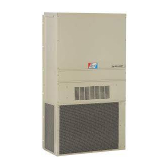
FOR USE WITH SH, WA AND WH SERIES
WALL MOUNTED AIR CONDITIONERS
(See Tables 1A, 1B and 1C for Model Usage Matrix)
EHWH02A-A04
EHWH02A-A08
EHWH24-B06
EHWH24B-C06
EHWH30-A05
EHWH36-A05
EHWH30-A10
EHWH36-A10
EHWH36-A15
EHWH03-B06
EHWH03-B09
EHWH36-B15
EHWH37-B15
EHWH31-C06
EHWH03A-C15
EHWC03A-C06
EHWC03A-C09
AND HEAT PUMPS
BARD MANUFACTURING COMPANY
Bryan, Ohio 43506
Since 1914...Moving, ahead just as planned.
EHWA24A-A04
EHWA02-A05
EHWA02A-A08
EHWA02A-A10
EHWA24-B06
EHWA03-A05
EHWA03-A08
EHWA03-A10
EHWA03-A15
EHWA03-B06
EHWA03-B09
EHWA03-B15
EHWA03A-C15
EHSH31-A04
EHSH31-A08
EHSH31-B06
EHSH31-C06
Manual:
Supersedes: 2100-268E
File:
Date:
2100-268F
Volume III, Tab 18
05-28-03
Advertisement
Table of Contents

Related Manuals for Bard EHWH02A-A04


Summary of Contents for Bard EHWH02A-A04
-
Page 1: Installation Instructions
FOR USE WITH SH, WA AND WH SERIES WALL MOUNTED AIR CONDITIONERS AND HEAT PUMPS (See Tables 1A, 1B and 1C for Model Usage Matrix) Manual: 2100-268F BARD MANUFACTURING COMPANY Supersedes: 2100-268E Bryan, Ohio 43506 File: Volume III, Tab 18 Date: 05-28-03 Since 1914...Moving, ahead just as planned. -
Page 2: Table Of Contents
Table 1B Approved Heater Usage Matrix ..3 Table 1C Approved Heater Usage Matrix ..3 Table 2 Electrical Data and BTU Output ..4 Table 3 References to Figures 4 & 5 By Model Number ......8 COPYRIGHT MAY 2003 BARD MANUFACTURING COMPANY BRYAN, OHIO 43506... -
Page 3: Model Nomenclature Legend
Remove the heat package from the shipping carton. The for use with Bard wall mount hi boy air conditioners and heat package must consist of the following: heat pumps. The packages consist of the electric heat 1. -
Page 4: Figure
Manual 2100-268 Page... -
Page 5: Figure
WARNING Only use factory provided heaters in approved combinations of heater models to unit models as shown in table 1A, 1B and 1C. Failure to use approved combinations as shown or modification to heaters could result in fire causing damabe, bodily injury or death. -
Page 6: Figure
TABLE 2 ELECTRICAL DATA AND BTU OUTPUT Manual 2100-268 Page... -
Page 7: Figure 1
FIGURE 1 WIRING – MAIN POWER MIS-365 Manual 2100-268 Page... -
Page 8: Installation
2. All heater packages covered by this manual are 3. Remove electric heater access panel and control factory wired for single supply circuit. The panel cover, both inner and outer. See Figure 2. following heater packages are field convertible to a 4. -
Page 9: Control Panel Cover Locations
FIGURE 3 FIGURE 2 SCREW MOUNTING HOLES ELECTRIC HEATER ACCESS PANEL AND CONTROL PANEL COVER LOCATIONS MIS-358 MIS-419 Manual 2100-268 Page... -
Page 10: Table 3
TABLE 3 REFERENCES TO FIGURES 4 AND 5 FOR MODEL NUMBER Manual 2100-268 Page... -
Page 11: A Thru D
FIGURE 4 A THRU D FIGURE 4C FIGURE 4A FIGURE 4B FIGURE 4D Manual 2100-268 Page... -
Page 12: Two Heat Strips
FIGURE 4E INSTALL HEATER PACKAGE WITH TWO HEAT STRIPS MIS-364 Manual 2100-268 Page... -
Page 13: Installing Heater Base And Connecting
FIGURE 5 INSTALLING HEATER BASE AND CONNECTING MIS-422 Manual 2100-268 Page... -
Page 14: Serial Plate Showing Approved Heater Packages
Manual 2100-268 Page...