Mitsubishi Electric MSZ-GA50VA Service Manual
Hide thumbs
Also See for MSZ-GA50VA:
- Operating instructions manual (134 pages) ,
- Service manual (32 pages) ,
- Installation manual (9 pages)
Advertisement
Table of Contents
- 1 Table of Contents
- 2 Service Manual
- 3 Technical Changes
- 4 Part Names and Functions
- 5 Specification
- 6 Noise Criteria Curves
- 7 Outlines and Dimensions
- 8 Wiring Diagram
- 9 Refrigerant System Diagram
- 10 Service Functions
- 11 Troubleshooting
- 12 Disassembly Instructions
- 13 Parts List
- 14 Electrical Parts
- 15 Optional Parts
- Download this manual
See also:
Service Manual
SPLIT-TYPE, HEAT PUMP AIR CONDITIONERS
SERVICE MANUAL
Wireless type
Models
MSZ-GA50VA -
MSZ-GA60VA -
MSZ-GA71VA -
Indication of model name
MSZ-GA50VA -
MSZ-GA60VA -
MSZ-GA71VA -
NOTE:
This service manual describes technical data of the indoor unit.
•As for outdoor units MUZ-GA50VA -
service manual OB389.
•As for outdoor units MXZ-3A54VA -
service manual OB377.
E1
E1
E1
CONTENTS
1. TECHNICAL CHANGES ····································2
2. PART NAMES AND FUNCTIONS······················3
3. SPECIFICATION·················································5
4. NOISE CRITERIA CURVES ·······························6
5. OUTLINES AND DIMENSIONS ·························7
6. WIRING DIAGRAM ············································8
7. REFRIGERANT SYSTEM DIAGRAM ················9
8. SERVICE FUNCTIONS ····································10
9. TROUBLESHOOTING······································12
10. DISASSEMBLY INSTRUCTIONS·····················24
E1
11. PARTS LIST······················································27
E1
12. OPTIONAL PARTS ······················BACK COVER
E1
, MUZ-GA60VA -
and MUZ-GA71VA -
E1
E1
, MXZ-4A71VA -
and MXZ-4A80VA -
E1
E1
No. OB388
, refer to the
E1
, refer to the
E1
Advertisement
Table of Contents

Related Manuals for Mitsubishi Electric MSZ-GA50VA


Summary of Contents for Mitsubishi Electric MSZ-GA50VA
-
Page 1: Table Of Contents
SPLIT-TYPE, HEAT PUMP AIR CONDITIONERS No. OB388 SERVICE MANUAL Wireless type Models MSZ-GA50VA - MSZ-GA60VA - MSZ-GA71VA - CONTENTS 1. TECHNICAL CHANGES ····································2 2. PART NAMES AND FUNCTIONS······················3 3. SPECIFICATION·················································5 4. NOISE CRITERIA CURVES ·······························6 5. OUTLINES AND DIMENSIONS ·························7 6. -
Page 2: Technical Changes
TECHNICAL CHANGES MSZ-A18YV - MSZ-GA50VA - MSZ-A24YV - MSZ-GA60VA - MSZ-A26YV - MSZ-GA71VA - 1. Indication of capacity has been changed.(BTU base kW base) 2. Power supply cord has been removed. 3. Indoor electronic control P.C. board has been changed. -
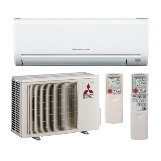
Page 3: Part Names And Functions
PART NAMES AND FUNCTIONS INDOOR UNIT MSZ-GA50VA - MSZ-GA60VA - MSZ-GA71VA - Air cleaning filter (option) Grille (Anti-allergy enzyme filter:blue bellows type) Air inlet Catechin air filter Remote control receiving section Vertical vanes Horizontal vane Remote controller Operation section Display section... - Page 4 REMOTE CONTROLLER MSZ-GA50VA - MSZ-GA60VA - MSZ-GA71VA - Signal transmitting section Operation display section OPERATE /STOP (ON /OFF)button ON/OFF WARM COOL TEMPERATURE buttons Indication of remote controller model is on back. Open the front lid. WIDE VANE button (Vertical vane button)
-
Page 5: Specification
SPECIFICATION Indoor model MSZ-GA50VA - MSZ-GA60VA - Cooling Heating Function Cooling Heating Single phase Single phase Power supply 230V, 50Hz 230V, 50Hz Capacity Air flow(High/Med. /Low ) K /h 852/690 /498 1,032/768 /522 1,032/786 /522 Power outlet Running current 1 0.45... -
Page 6: Noise Criteria Curves
Specifications and rating conditions of main electric parts INDOOR UNIT Model MSZ-GA71VA - MSZ-GA50VA - MSZ-GA60VA - Item (F11) T3.15AL 250V Fuse (MV1/ MV2) MP20/MP20 Vane motor (NR11) Varistor ERZV14D471 (TB) Terminal block NOISE CRITERIA CURVES MSZ-GA50VA - MSZ-GA60VA -... -
Page 7: Outlines And Dimensions
OUTLINES AND DIMENSIONS MSZ-GA50VA - Unit: mm MSZ-GA60VA - MSZ-GA71VA - INDOOR UNIT Installation plate Indoor unit 1068 414.5 414.5 Wall hole [75 Liquid line [ 6.35- 0.5m 1100 Air in Installation plate Gas line [ 12-0.43m Insulation [ 50 O.D [ 32 I.D... -
Page 8: Wiring Diagram
WIRING DIAGRAM MSZ-GA50VA - MSZ-GA60VA - MSZ-GA71VA - MODELS WIRING DIAGRAM INDOOR UNIT INDOOR ELECTRONIC CONTROL P.C. BOARD RT13 TAB3 230V~ RT12 DB111 T111 TO OUTDOOR UNIT RT11 12-24V NR11 CONNECTING CN201 LD104 CN211 105(T) POWER MONITOR RECEIVER SW P.C. -
Page 9: Refrigerant System Diagram
REFRIGERANT SYSTEM DIAGRAM MSZ-GA50VA - MSZ-GA60VA - Unit:mm INDOOR UNIT INDOOR UNIT Refrigerant pipe [15.88 Refrigerant pipe [12.7 (with heat insulator) (with heat insulator) Indoor coil Indoor coil thermistor Indoor Indoor thermistor RT12(main) heat RT12(main) heat exchanger exchanger Distributor Distributor... -
Page 10: Service Functions
SERVICE FUNCTIONS MSZ-GA50VA - MSZ-GA60VA - MSZ-GA71VA - 8-1. TIMER SHORT MODE For service, set time can be shortened by short circuit of JPG and JPS on the electronic control P.C. board. The time will be shortened as follows. Set time : 1 minute... - Page 11 Operation If the main power has been cut, the operation settings remain. After the power is restored, the unit restarts automatically according to the memory.(However, it takes at least 3 minutes for the compressor to start running.) How to release “AUTO RESTART FUNCTION” Turn off the main power for the unit.
-
Page 12: Troubleshooting
TROUBLESHOOTING MSZ-GA50VA - MSZ-GA60VA - MSZ-GA71VA - 9-1. Cautions on troubleshooting 1. Before troubleshooting, check the following: (1) Check the power supply voltage. (2) Check the indoor/outdoor connecting wire for mis-wiring. 2. Take care the following during servicing. (1) Before servicing the air conditioner, be sure to turn off the unit first with the remote controller, and then after confirming the horizontal vane is closed, turn off the breaker and / or disconnect the power plug. - Page 13 9-2. Failure mode recall function Outline of the function This air conditioner can memorize the abnormal condition which has occurred once. Even though OPERATION INDICATOR lamp indication listed on the troubleshooting check table (9-4.) disappears, the memorized failure details can be recalled. This mode is very useful when the unit needs to be repaired for the abnormality which doesn't recur.
- Page 14 2. Indoor unit failure mode table NOTE:Blinking patterns of this mode differs from the ones of Troubleshooting check table(9-4.). Left lamp of Abnormal point Detection method Check point OPERAITON (Failure mode) INDICTOR Not lighted Normal – – When the room temperature thermistor short Room temperature Refer to the characteristics of room 1-time flash...
- Page 15 9-3. Instruction of troubleshooting Start Indoor unit Indoor unit Indoor unit operates. OPERATION INDICATOR operates. doesn't receive Outdoor unit doesn't lamp on the indoor unit is Outdoor unit the signal from operate normally. flashing on and off. doesn't remote controller. operate.
- Page 16 9-4. Troubleshooting check table · Flashing of OPERATION INDICATOR lamp (left-hand side lamp) Lighted indicates abnormalities. Blinking Not Lighted NOTE : Before taking measures, make sure that the symptom reappears for accurate troubleshooting. Self check table Abnormal Operation indicator lamp Symptom Detection method Check point...
- Page 17 NOTE : When the indoor unit has started operation and the above detection method has detected an abnormality (the first detection after the power ON), the indoor electronic control P.C. board turns OFF the indoor fan motor with OPERATION INDICATOR lamp flashing. 9-5. Trouble criterion of main parts MSZ-GA50VA - MSZ-GA60VA - MSZ-GA71VA - Part name...
- Page 18 9-6. Troubleshoot flow When OPERATION INDICATOR lamp flashes 3-time. Indoor fan does not operate. Check of indoor fan motor The indoor fan motor error has occurred, and the indoor fan doesn't operate. Turn OFF the power supply. Insert a stick such as a screw driver into the air outlet, and check if there is any catch in the rotation of the line Pay careful attention to the high voltage on...
- Page 19 Indoor unit operates by pressing EMERGENCY OPERATION switch, but does not operate with the remote controller. Check of remote controller and receiver P.C. board wCheck if the remote controller is exclusive for this air conditioner. Switch on the remote controller. Is LCD display on the the remote Replace the batteries.
- Page 20 The unit does not operate with the remote controller. Also, OPERATION INDICATOR lamp does not light up by pressing EMERGENCY OPERATION switch. Check of indoor electronic control P.C. board and indoor fan motor Turn OFF the power supply. Measure the resistance between CN211 3 Remove indoor fan motor connector CN211 and Short circuit: and 4 of the indoor fan motor connector.
- Page 21 • When unit cannot operate neither by the remote controller nor by EMERGENCY OPERATION switch. Indoor unit does not operate. • When OPERATION INDICATOR lamp flashes ON and OFF in every 0.5-second. Outdoor unit does not operate. How to check mis-wiring and serial signal error (when outdoor unit does not work) Turn OFF the power supply.
- Page 22 Electromagnetic noise enters into TV sets or radios Is the unit earthed? Earth the unit. Is the distance between the Extend the distance between antennas and the indoor the antennas and the indoor unit within 3m, or is the unit, or the antennas and the distance between the outdoor unit.
- Page 23 9-7. Test point diagram and voltage MSZ-GA50VA - MSZ-GA60VA - MSZ-GA71VA - Indoor electronic control P.C. board Release of Auto restart Power supply input function Varistor (NR11) 230V AC Fuse(F11) Solder the Jumper wire to JR07. (Refer to 8-3.) Indoor fan motor...
-
Page 24: Disassembly Instructions
1Hold the sleeve, and 2Pull the terminal while pull out the terminal pushing the locking slowly. Locking lever lever. Connector MSZ-GA50VA - MSZ-GA60VA - MSZ-GA71VA - INDOOR UNIT OPERATING PROCEDURE PHOTOS 1. Removing the front panel Photo 1 (1) Remove the screw caps of the front panel. - Page 25 OPERATING PROCEDURE PHOTOS Indoor coil Screw of the 3. Removing the electrical box Photo 3 thermistors ground wire (1) Remove the front panel. (Refer to 1.) (2) Remove the electrical cover. (Refer to 2.) (3) Disconnect the connector of the indoor coil thermistors. (4) Disconnect the motor connector (CN211) and the vane motor connector (CN151 and CN152) on the electronic control P.C.
-
Page 26: Parts List
PARTS LIST MSZ-GA50VA - (WH) MSZ-GA60VA - (WH) MSZ-GA71VA - (WH) 11-1. INDOOR UNIT STRUCTURAL PARTS 11-2. INDOOR UNIT HEAT EXCHANGER CATCH Optional parts (See 12.) SCREW 11-1. INDOOR UNIT STRUCTURAL PARTS Part number that is circled is not shown in the illustration. -
Page 27: Electrical Parts
MSZ-GA50VA - (WH) MSZ-GA60VA - (WH) MSZ-GA71VA - (WH) 11-4. ACCESSORY AND 11-3. INDOOR UNIT FUNCTIONAL PARTS AND REMOTE CONTROLLER ELECTRICAL PARTS SLEEVE BEARING ROOM TEMPERATURE THERMISTOR VARISTOR FUSE SW P.C. BOARD 11-3. INDOOR UNIT FUNCTIONAL PARTS AND ELECTRICAL PARTS Part numbers that are circled are not shown in the illustration. -
Page 28: Optional Parts
Air cleaning filter (Anti-allergy enzyme filter:blue bellows type) HEAD OFFICE: MITSUBISHI DENKI BLDG., 2-2-3, MARUNOUCHI, CHIYODA-KU, TOKYO100-8310, JAPAN C C Copyright 2005 MITSUBISHI ELECTRIC ENGINEERING CO.,LTD New publication, effective Jan. 2005 Distributed in Jan. 2005. No.OB388 6 Specifications subject to change without notice.