Table of Contents
Advertisement
Advertisement
Table of Contents

Related Manuals for Skyworth 42E68


Summary of Contents for Skyworth 42E68
-
Page 1: Service Manual
SERVICE MANUAL 5M92A CHASSIS Design and specifications are subject to change without prior notice. (Only Referrence) SERVICE MANUAL 8M48A Description: SKYWORTH MODEL. Brand Name: JOB NO. Engineering Dept: 2012-02-28 Artwork By: Date: SIZE:A5 Checked By: Date: Approved By: Date:... - Page 2 Content--------------------------------------------------------------2 11-41 43-44 45-53 54-80 81-84 85-94...
- Page 3 LED 8M26A...
- Page 4 PAL SECAM / BG DK PAL / I NTSC / M 44.25MHz ~ 140.25MHz VHF LOW K1~S6 147.25MHz ~ 423.25MHz VHF HIGH S7~S36 431.25MHz ~ 863.25MHz S37~DS57 Asia\Europe TOSHIBA CODE Component...
- Page 5 For 22” LED For 24” LED For 32” LED...
- Page 6 (24 inches is 4 ohm) (24 inches is 3W)
- Page 7 (26inches is 8 ohm) 12000...
- Page 8 Standard Standard Spanish...
- Page 9 30000...
-
Page 11: Connection Diagram
AP1117 1A LOW DROPOUT POSITIVE ADJUSTABLE OR FIXED-MODE REGULATOR Typical Application Circuit 10uF 10uF 2.5V/1A 3.3V/1A 22uF 22uF Tab is V Tab is V ( 5V/3.3V fixed output ) ( 5V/2.5V ADJ output ) Note: Connection Diagram 3 PIN SOT223 3 PIN TO252 / TO263 ( Top View ) ( Top View ) - Page 12 AP1117 1A LOW DROPOUT POSITIVE ADJUSTABLE OR FIXED-MODE REGULATOR Block Diagram 1.25V CURRENT LIMIT (FIXED) Thermal Shutdown Pin Descriptions NAME PIN # FUNCTION A resistor divider from this pin to the V pin and ground sets the output voltage Adj (GND) (Ground only for Fixed-Mode).
-
Page 13: Pin Configurations
A1semi 1A Fixed and Adjustable Low AS1117 Electronics Ltd Dropout Linear Regulator(LDO) Pin Configurations L Package U Package (SOT-223) (SOT-89) INPUT INPUT OUTPUT OUTPUT ADJ/GND ADJ/GND T Package R Package (TO-220) (TO-252) INPUT INPUT OUTPUT OUTPUT ADJ/GND ADJ/GND S Package (TO-263) INPUT OUTPUT... - Page 14 A1semi 1A Fixed and Adjustable Low AS1117 Electronics Ltd Dropout Linear Regulator(LDO) Functional Block Diagram INPUT Thermal Shutdown OUTPUT GND (Fixed Output) ADJ (Adjustable Output) Figure 3. Functional Block Diagram of AS1117 http://www.a1semi.com A1 SEMI ELECTRONICS LTD.
- Page 15 AOZ1051PI EZBuck™ 3 A Synchronous Buck Regulator General Description Features The AOZ1051PI is a high efficiency, easy to use, 3 A 4.5 V to 18 V operating input voltage range synchronous buck regulator. The AOZ1051PI works from Synchronous Buck: 70 m internal high-side switch 4.5 V to 18 V input voltage range, and provides up to 3 A and 40 m internal low-side switch (at 12 V)
-
Page 16: Pin Configuration
AOZ1051PI Ordering Information Part Number Ambient Temperature Range Package Environmental AOZ1051PI -40 °C to +85 °C EPAD SO-8 Green Product AOS Green Products use reduced levels of Halogens, and are also RoHS compliant. Please visit www.aosmd.com/web/quality/rohs_compliant.jsp for additional information. Pin Configuration PGND (LX) AGND... - Page 17 AOZ1051PI Block Diagram Internal UVLO 5V LDO & POR Regulator ISen Reference Softstart – & Bias ILimit 5μA Level 0.8V Shifter EAmp – Control Comp – Logic Driver COMP 500kHz Oscillator PGND AGND Absolute Maximum Ratings Recommended Operating Conditions Exceeding the Absolute Maximum Ratings may damage the The device is not guaranteed to operate beyond the Maximum device.
- Page 18 SY8086 High Efficiency 1.4MHz, 1A Synchronous Step Down Regulator Preliminary Specification General Description Features • Low R The SY8086 is a high-efficiency 1.4MHz synchronous for internal switches (top/bottom): DS(ON) 250m Ω /200m Ω step-down DC-DC regulator ICs capable of delivering •...
- Page 19 SY8086 Pinout (top view) SOT23-5 Top mark: BE xyz (Device code: BE, x=year code, y=week code, z= lot number code) Pin Name Pin Number Pin Description Enable control. Pull high to turn on. Do not float. Ground pin Inductor pin. Connect this pin to the switching node of inductor Input pin.
- Page 20 IC Block Diagram U10(LCDTV CONTROLLER WITH VIDEO ECODE)MST6E181VS PIN DIAGRAM (MST6E181VS) -13-...
- Page 21 "pdfFactory Pro" www.fineprint.cn...
- Page 22 "pdfFactory Pro" www.fineprint.cn...
- Page 23 "pdfFactory Pro" www.fineprint.cn...
- Page 24 "pdfFactory Pro" www.fineprint.cn...
- Page 25 "pdfFactory Pro" www.fineprint.cn...
- Page 26 "pdfFactory Pro" www.fineprint.cn...
- Page 27 "pdfFactory Pro" www.fineprint.cn...
- Page 28 "pdfFactory Pro" www.fineprint.cn...
- Page 29 "pdfFactory Pro" www.fineprint.cn...
- Page 30 "pdfFactory Pro" www.fineprint.cn...
- Page 31 "pdfFactory Pro" www.fineprint.cn...
- Page 32 "pdfFactory Pro" www.fineprint.cn...
- Page 33 "pdfFactory Pro" www.fineprint.cn...
- Page 34 "pdfFactory Pro" www.fineprint.cn...
- Page 35 "pdfFactory Pro" www.fineprint.cn...
- Page 36 "pdfFactory Pro" www.fineprint.cn...
- Page 37 IC Block Diagram -15-...
- Page 38 IC Block Diagram U19(HDMI SWITCH) PS331TQFP64G SiI9185 Pin Mapping POWDN POW_SINK REXT HPD3 SDA3 SCL3 POW3 PS331 SCL1 SDA1 I2C_RST CEXT -16-...
- Page 39 PS331 HDMI/DVI SWITCH Parade Technologies Inc. Table1. Pin Descriptions Name Description x = 1, 2, 3 for TMDS input channel number y = 1, 2, 3, 4 for TMDS positive differential data or clock inputs x = 1, 2, 3 for TMDS input channel number y = 1, 2, 3, 4 for TMDS negative differential data or clock inputs x = 1, 2, 3, 4 for TMDS positive differential outputs x = 1, 2, 3, 4 for TMDS negative differential outputs...
- Page 40 TAS5707 SLOS556A – NOVEMBER 2008 – REVISED APRIL 2009 ..............................www.ti.com 48-TERMINAL, HTQFP PACKAGE (TOP VIEW) PHP Package (Top View) 48 47 46 45 44 43 42 41 40 39 38 37 OUT_A OUT_D PVDD_A PVDD_D PVDD_A PVDD_D BST_A BST_D GVDD_OUT GVDD_OUT VREG...
- Page 41 TAS5707 www.ti.com ..............................SLOS556A – NOVEMBER 2008 – REVISED APRIL 2009 PIN FUNCTIONS (continued) TYPE TERMINATION DESCRIPTION TOLERANT NAME – No connection OC_ADJ Analog overcurrent programming. Requires resistor to ground. OSC_RES Oscillator trim resistor. Connect an 18.2-k 1% resistor to DVSSO. OUT_A Output, half-bridge A OUT_B...
- Page 42 -18-...
- Page 45 8M48A/S Factory Adjust Menu (V0.0) 1. Description Enter factory mode: Open source menu, and then press digital button “3”, “1”, “9” , “5” in turns to enter the factory menu. Press ↑ and ↓ button to choose the item, press OK button enter the submenu, press MENU to ruturn to upper menu , press ←...
- Page 46 factory, select “AUTO ADC” item in the “ADC CALIBRATION” menu, press → button to begin auto adjust. When it is finish, it will show “OK” or “FAILE”. If “FAILE” is showed, you need to try again. NOTE: YPBPR ADC need to do twice by use 576P and 720P signal separate.
- Page 47 White balance: Enter factory mode, enter “W/B ADJUST” item, you can adjust white balance in this menu. Over scanning: Enter factory mode, enter “Panel SETTING” submenu, enter “OVERSCAN” submenu, you can adjust the over scan in these menu. OutFactory reset: Enter factory mode, enter “SYSTEM SETTING”...
- Page 48 Update software (by USB): Copy the new software (name by “MERGE.bin”) to the root directory of USB drive. Plug the drive to the USB2 socket (if there are two USB socket, make sure you use the socket 2). Enter factory, select “Software Update (USB)”...
-
Page 49: More Information
2. More information FACTORY MENU Default Value Remark ADC ADJUST MODE Select source R-GAIN Red gain G-GAIN Green gain B-GAIN Blue gain R-OFFSET Red offset G-OFFSET Green offset B-OFFSET Blue offset AUTO ADC Auto ADC calibration W/B ADJUST MODE Select source TEMPERATURE Select Neutral/Warm/Cool/Personal R-GAIN... - Page 50 LVDS BIT 8BitPanel PWMFREQUENCY PWM DUTY OVERSCAN OVERSCAN_RESLUTION HPOSITION Horizontal position VPOSITION Vertical position HSIZE Horizontal size VSIZE Vertical size SYSTEM SETTING FACHOTKEY Factory hot key enable TTX BRI Logo enable WHILE PATTERN NO USED POWER REMIND Preset the no signal standby time BULE SCREEN Blue or Black screen when no signal VIDEO AGC...
- Page 51 Channel Preset Reset channel to default NO SIGNAL MUTE AMP OUT FAC SOUND SYS AGC GAIN LANGUAGE SETTING 繁体中文 S-CHINESE 西班牙语 SPANISH 法语 FRENCH 葡萄牙语 PORTUGUESE 俄罗斯语 RUSSIAN 繁体中文 BIG CHINESE 保加利亚语 BULGARIAN 斯洛伐克语 SLOVAK 芬兰语 FINNISH 印度尼西亚 INDONESIA 阿拉伯语 ARABIC 阿拉伯语...
- Page 52 SCART HDMI1 HDMI2 HDMI3 YPbPr1 USB1 USB2 AGALOG CURVE MODE PICTURE MODE BRIGHTNESS CURVE CONTRAST CURVE SATURATION CURVE HUE CURVE SHARPNESS CURVE VOLUME CURVE BACKLIGHT HOTEL FUNCTION HOTEL MODE Hotel mode enable IR LOCK LOCAL KEY LOCK USER SETTING SAVE VOLUME FIXED POWER ON VOL VALUE...
- Page 53 MAX VOLUME POWER ON SOURCE SCALE LOCK CHANNEL SEARCH LOCK OTHER OPTION LVDS and DDR frequency setting UART DEBUG NO USED SPECIAL NO USED VIF1 VIF1 VIF setting VIF2 VIF-AGC-VGA-BASE item is used adjust TUNER AGC VIF3 POWER ON LOGO NONE Teletext NO USED...
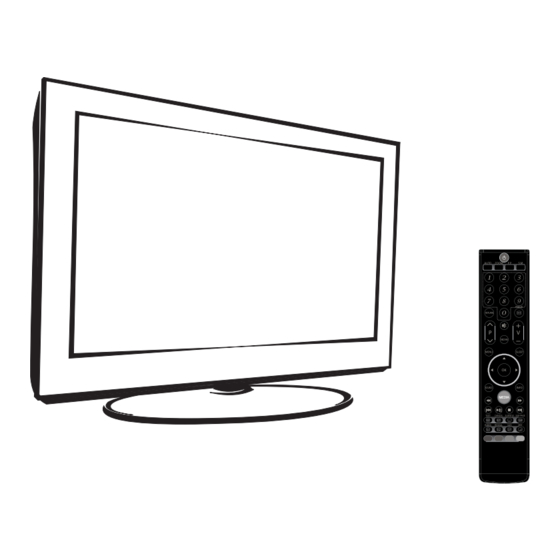
- Page 54 Instruction Manual 42E68 To obtain the best performance and safety, please read this manual carefully. Please keep this manual for future reference. Size:A5 Description: MANUAL(5M92A+3D) SKYWORTH Job No. Brand Name: 42E68 MODEL: P/No. REV: Scale: Engineering Dept: 2013-4-28 Artwork By:...
- Page 55 CONTENT CONTENT ......................1 WARNING AND PRECAUTION ................. 2-6 INTRODUCTION, FUNCTIONS AND FEATURES ..........7 EXTERNAL SCHEMATIC AND INSTALLATION ..........8-14 Front Panel ....................8 Back Panel ....................9 Front Remote Control ................10-12 Back Remote Control .................. 13 MENU CONTROL ..................14-18 Basic Operation ...................
- Page 56 WARNING AND PRECAUTION Read all of the instructions before operating the set. Keep these instructions well for later use. Warning Only use attachments/accessories specified or provided by the manufacturer (such as the exclusive supply adapter, battery etc). Please refer the information on exterior back enclosure for electrical and safety information before installing or operating the apparatus.
-
Page 57: Weee Directive
WARNING AND PRECAUTION Important Information For Australia Using cabinets or stands recommended by the manufacture of the television. Only using furniture that can safety support the television. Ensuring the television is not overhanging the edge of the supporting furniture. Not placing the television on tall furniture(for example, cupboards or bookcases) without anchoring both the furniture and the television to a suitable support. - Page 58 WARNING AND PRECAUTION Use Environment Do not install this equipment in a confined space such as a bookcase or similar unit. Do not use the set near damp, and cold areas, protect the set from overheating. Keep away from direct sunlight. Do not use the set near dust place.
- Page 59 WARNING AND PRECAUTION 3D Visual Function Proper Operation Guide Guide 1: Confirm whether the product presents three-dimensional effect If there is ghosting, or obvious discomfort when you're viewing stereoscopic video, please stop your watching and confirm if the settings of 3D products are correct (such as glasses / 3D TV switch / 3D format switch, etc.).
- Page 60 WARNING AND PRECAUTION Guide 6: Remind of low age audience Children under the age of 4 ~ 5 their eyes physiogeny are incomplete development, should be careful when they are watching the 3D products. Children should be observed and supervised by grownups when they watch three-dimensional video, and also their viewing time should be limited.
-
Page 61: Brief Introduction
INTRODUCTION, FUNCTIONS AND FEATURES Brief Introduction Thanks for your purchase of our digital high-definition LED television! This product with diverse functions is designed to fulfill the optimum requirements from commercial, industrial and household uses. LED television possesses the display function of both TV and PC. It features advanced picture performance, smaller in size and lighter in weight, meanwhile, consumes less power and makes no radiation. -
Page 62: External Schematic And Installation
EXTERNAL SCHEMATIC AND INSTALLATION Front Panel Note: The graphics are for representation only. PROG PROG 1.Power Button 2.Power Indicator / Remote Sensor 3.Speakers 4.Program Up/Down Button 5.Volume Up/Down Button 6.Menu Button 7.Source Button 8.Standby Button... -
Page 63: Back Panel
EXTERNAL SCHEMATIC AND INSTALLATION Back Panel Note: The graphics are for representation only. HDMI2 HDMI1 USB1 USB3 RF IN HDMI IN PC IN AUDIO IN service only S/PDIF 1. USB3: only for service to update software. 2. HDMI1\HDMI2: Connect HDMI input signal from signal source such as DVD. 3. - Page 64 EXTERNAL SCHEMATIC AND INSTALLATION Front Remote Control 1. POWER( Press to turn the TV on or off(standby). 2. MUTE( Press to mute or restore the volume. 3. Picture Mode( P.M. ) Press to select the desired picture mode. 4. Sound Mode( S.M. ) Press to select the desired sound mode.
- Page 65 EXTERNAL SCHEMATIC AND INSTALLATION Front Remote Control Android System Video/Music Player Control Buttons Play & Pause ( Press to pause playback, press again to continue playback. Stop ( Press the stop button to stop and go to the begin block of the video music. Fast Backward Button( Press to fast reverse.
- Page 66 EXTERNAL SCHEMATIC AND INSTALLATION Front Remote Control 25. Power Indicate When this LED turn on, it mean by the battery is short of power, you may change battery. SIZE/ REVEAL/ MIX/SUB-PAGE/INDEX/ CANEL Teletext Control Button SIZE Enlarge the teletext display: Press this button once to enlarge upper half of the screen.
- Page 67 EXTERNAL SCHEMATIC AND INSTALLATION Back Remote Control Keyboard on/off button. 28. Keyboard Android System input keyboard. Note: The keyboard and Mouse button must with a usb dongle insert a side USB port. -13-...
-
Page 68: Menu Control
MENU CONTROL This section explains the menus of your TV. Each menu is outlined and detailed to help you get the most from your TV. Basic Operation 1. Press MENU on the remote control or on the TV key panel to display the main menu. 2. -
Page 69: Sound Settings
MENU CONTROL Neutral: Keep the original white. Warm: Red. Personal: The user may customize the color temperature.(Red/Green/Blue). Cool: Blue. Display Mode PICTURE Press " " or " " to select display mode including: Panorama, Movie, Caption, 16:9, 4:3, Just Scan and Display Mode 16:9 Auto. - Page 70 MENU CONTROL Installation Settings Note: These settings are only available in TV mode. Channel No. INSTALLATION Sets the received TV channel No. Channel No. Color System Color system Sound System Selects color system. Auto Search Manual Search Fine Tuning 183.5MHz Sound system Channel Skip Selects sound system.
-
Page 71: Setup Settings
MENU CONTROL Setup Settings OSD Language SETUP Select you desired OSD language. OSD Language English TTX Language TTX Language Russian Select the desired Teletext language: West Europe / Nicam Mono East Europe / Russian / Arabic. User Reset Sleep Timer Nicam (Option) "... - Page 72 MENU CONTROL 3D Settings 2D TO 3D Left right Right Strong Top bottom Left Middle Frame sequence Weak 3D FORMAT LEFT/RIGHT 3D TO 2D DEPTH 3D FORMAT 5 Modes: 2D TO 3D, Off, Left right, Top bottom, Frame sequence. LEFT/RIGHT Select "On" to swap Left & Right if the source video. 3D TO 2D In 3D mode, select the "Left"...
- Page 73 HOME CONTROL Basic Operations After connect to the USB mouse/keyboard, Smart system can operate. The basic operation is similar to Android tablet computer windows. The Android desktop has a total of five, the middle one as the default main desktop, both sides there are two. You can hold down the mouse move for switching different desktop.
- Page 74 HOME CONTROL Change Display Resize Follow this path you can change display resize: Settings Display Output settings Change display resize. Font Size Follow this path you can change font size: Settings Display Font Size. Apps You can see a list of all applications installed on the device from the Apps setting Item, also can Force stop, Disable/enable from the App control Item.
- Page 75 HOME CONTROL Android System Specifications Design, specifications, and manual are subject to change without notice. Cortex -A5 (1GHZ) Processor 512MB Built-in-Storage is model dependant and indicated Storage on product packaging. (E.g.-4=4GB) microSDHC card slot (max. 32GB sup-ported) Display 720P 50Hz/60Hz Networking Wi-Fi(802.11 b/g/n) Video Output...
-
Page 76: Troubleshooting
TROUBLESHOOTING NO PICTURE, NO SOUND SNOWY DOTS AND INTERFERENCE If the antenna is located in the fringe area of a 1. Check if the fuse or circuit breaker is working. television signal where the signal is weak, the 2. Plug another electrical device into the outlet to picture may be marred by dots. -
Page 77: Specifications
SPECIFICATIONS Screen size - diagonal: 107cm Screen resolution: 1920X1080 Audio output power (L+R): 8W + 8W Working voltage: 100-240V~ 50/60Hz Rated power consumption: 120W Dimensions (W x D x H): 965 X 258 X 641mm 14.8Kg Net weight: Environment (only for Tropical climates zone) Working temperature: 5 C~45 C Working humidity: 20%~80% Storage temperature: -15C~50 C... - Page 79 Service Flow Chart Has video but no audio Check if the Volume has set to “0” or if the it is mute Done Check the audio input line & the audio input circuit. Done Check the voltage of “Mute” pin beside the amplifier IC.
- Page 80 Service Flow Chart Has video but no color Check the Color / Saturation in picture menu if it has decreased to “0” Check the cable input if Increase the item it has exactly connected to default “50” Done Well connect the cable Check the current input source if it is TV Change the main...
- Page 82 当使用主控IC的RESET时可以取消RESET电路 R561 R561 AUMCK_I2S_OUT/ AE_SCL TUNER_SCL TUNER_SCL AUMCK_I2S_OUT AUBCK_I2S_OUT/ R582 R582 AUWS_I2S_OUT/ VDD_3.3V AUWS_I2S_OUT VDD_3.3V AE_SDA TUNER_SDA AUWS_I2S_OUT/ TUNER_SDA R558 R558 AUBCK_I2S_OUT/ AUBCK_I2S_OUT OPTION AUSD_I2S_OUT/ R560 R560 AUSD_I2S_OUT/ AUSD_I2S_OUT SDO0_AMP_I2S GPO07/SDO1/REF R100 R100 R121 R121 NC/10K NC/10K 1N4148 1N4148 靠近主控AMP IC输出端放置 8.2K 8.2K BCK_AMP_I2S...
- Page 83 1N4148 1N4148 +5V_Normal +3.3V_Normal R228 R228 4.7K 4.7K BH3544F BH3544F MUTE CONTROL AMP_AUOUTL0 AMP_AUOUTL0 EARPHONE_JACK_R OP_VCC1 EARPHONE_JACK_L MUTE 2.2uF 2.2uF R450 R450 BIAS R219 R219 100K 100K +12V_NORMAL VCC_5711 CA120 CA120 OP_VCC1 CA119 CA119 3904 3904 EP_AMP_MUTE 47uF/16V 47uF/16V R445 R445 47uF/16V 47uF/16V...
- Page 84 BPF FOR 38.9MHz OR 38MHZ HFT2-8F/115CW HFT2-8F/115CW C379 C379 C356 C356 C370 C370 IF-IN- 0.1u 0.1u C380 C380 C376 C376 VIFM VIFM 0.1u 0.1u C371 C371 C362 C362 BPF_IN Q值:15(MIN) 100nH_10% 100nH_10% 220p 220p C377 C377 C373 C373 +5V_Tuner IF-IN+ 0.1u 0.1u C368...
- Page 85 Coaxial Output CON7 CON7 DIP2x7PIN DIP2x7PIN AV_L R507 R507 AV_AULin0 AV_AULin0 AV_R AV_L R511 R511 AV_V RCA1 RCA1 AV1R AV2_R AV1L AV2_L HD_Pr C384 C384 HD_Y HD_Pb SPDIF_OUT 330R 330R AV_R R512 R512 AV_AURin0 DD31 DD31 R158 R158 AV_AURin0 100R 100R RCA1 RCA1...
- Page 86 PHONEJACK STEREO SW 180d PHONEJACK STEREO SW 180d R154 R154 6100-020100-0410 VGA-AURin0 DD19 DD19 R153 R153 200p 200p VGA-Rin1 ESD-0402 ESD-0402 VGA-Lin1 R155 R155 VGA-AULin0 DD20 DD20 R156 R156 200p 200p ESD-0402 ESD-0402 PHONEJACK PHONEJACK 6100-020000-0410 UART-RX0 R149 R149 UART-RX VGA-Bin RGB0_Pb+ RGB0_Pb+...
- Page 87 USB_A USB_A +5V_USB2 USB2_D1-_in USB2_D- USB2_D- +5V_Normal +5V_USB1 USB2_D1+_in USB2_D+ USB2_D+ FB/NC FB/NC 100K 100K +3.3V_Normal +5V_USB1 CA111 CA111 R145 R145 FLG# 100uF/16V 100uF/16V VOUT +5V_USB2 USB2_D1-_in USB2_D1+_in USB_ON1 4.7K 4.7K ON_USB1_MOS USB_ON1 0.1uF 0.1uF NC/G5250F2 NC/G5250F2 USB_A USB_A USB_A USB_A +5V_Normal +5V_USB2...
- Page 88 HDMI BYPASS OPTION SDA_HD R251 R251 0R/NC 0R/NC SDA2 B_TX0+ SCL_HD R249 R249 0R/NC 0R/NC SCL2 HDMI2-RX0P B_TX0- HPD_SINK R252 R252 0R/NC 0R/NC HPD2 HDMI2-RX0N G_TX1+ HDMI2-RX2P 0ohmX4/NC 0ohmX4/NC IN2D2+ HDMI2-RX1P HDMI3_5V G_TX1- HDMI2-RX2N IN2D2- HDMI2-RX1N R_TX2+ HDMI2-RX1P IN2D1+ HDMI2-RX2P HDMI HDMI R_TX2-...
- Page 89 DDR2 VREF +2.5V_PGA R590 R590 0/NC 0/NC LVDS OUT AVDD_DDR TUNER_SCL Connector VDDC AVDD_DDR AVDD_33 R104 R104 R104 1K_1% 1K_1% CON1 CON1 ADC2P5 AVDD_33_PM MDDR_VREF R589 R589 0/NC 0/NC +3.3V_Normal TUNER_SDA R106 C113 C114 RXO0- R7_RXO0- RXO0+ R6_RXO0+ R6_RXO0+ R7_RXO0- R106 R106 C113...
- Page 90 +12V_NORMAL 定位孔 +5V_Standby +5V_Standby +3.3V_Standby +5V_Normal 0.1uF 0.1uF BL-ON/OFF BL-ADJUST AOZ1051PI AOZ1051PI C148 C148 +5V_Normal/ STANDBY 0.1uF 0.1uF 22uH 22uH R342 R342 R343 R343 EXPAD/LX CA19 CA19 +5V_Standby 4.7K 4.7K 4.7K 4.7K 2.2K 2.2K 4.7K 4.7K COMP 0.1uF 0.1uF R347 R347 NC/0 NC/0...
- Page 91 20110826 更改的部分: 1.PAGE 08_AUDIO AMP 更改部分,增加R926(470R)、R927(470R)。 目的为了解决开战频底噪问题。 20110901 1.PAGE 02_MST6M161LG AMS1117_adj 的1脚反馈电压 是 相对2脚OUT的,即2脚 和1脚的相对电压为1.25V,所以将R23改为220R,将R25改为100R <OrgName> <OrgName> <OrgName> SMC 0755-26037700 Title Title Title MST6M161LG&181VG&182VG MST6M161LG&181VG&182VG MST6M161LG&181VG&182VG Size Size Size Document Number Document Number Document Number Custom Custom Custom MST6M161LG&181VG&182VG MST6M161LG&181VG&182VG MST6M161LG&181VG&182VG V1.0 V1.0...