Epson EMP-S4 Service Manual
Hide thumbs
Also See for EMP-S4:
- User manual (77 pages) ,
- Quick start manual (26 pages) ,
- Specifications (2 pages)
Table of Contents
Advertisement
Quick Links
Advertisement
Table of Contents
Troubleshooting

Related Manuals for Epson EMP-S4


Summary of Contents for Epson EMP-S4
- Page 1 Data Projector Service Manual EMP-S4...
- Page 2 This Service Manual describes the hardware information necessary for troubleshooting and field service of the EMP-S4 DATA PROJECTOR. Before starting service on this unit, always check the EPSON website for additional up-to date service information provided in Technical Information Bulletins.
- Page 3 REASSEMBLY CHECK POINT C H E C K Important tips for procedures are described under the heading CHECK POINT P O I N T 2006 SEIKO EPSON CORPORATION SEIKO EPSON Revision:B...
- Page 4 EMP-S4 Manual Revision History History Date Detail of change First Release Rev.A 2006.4.10 Rev.B 2006.5.9 Change in P.4-10. Service memo Make a note here of important technical information from Technical Information bulletins. SEIKO EPSON Revision:B...
-
Page 5: Safety Instructions
EMP-S4 SAFETY INSTRUCTIONS 1. MAINTAINING OPERATOR SAFETY 1. PREVENTING ELECTRIC SHOCKS • Turn off the power switch and disconnect the power cord from the AC outlet before car- rying out any disassembly and assembly work on this projector. • If power needs to be supplied to the projector while the cover is removed (such as when... - Page 6 • When replacing the structural components inside the projector (including the lamp assy), use only replacement parts supplied by EPSON and listed in the projector's Parts List. • Use the accessory power cord and interface cable provided with the projector.
- Page 7 EMP-S4 Testing procedure Carry out testing in the order given below. Repair Insulation resistance test Ground continuity check Illumination check Safety inspections Testing methods 1). Insulation resistance test • Testing apparatus: Insulation ohmmeter (Rating: 500 V/100 MΩ) Check Item Tool...
- Page 8 EMP-S4 2). Ground continuity check • Testing apparatus: Multimeter (with sensitivity down to 0.1 Ω) Check Item Tool Standard Should be no resistance Ground continuity check Multimeter (0.5 Ω or less) • Multimeter settings Display 1. Turn on the power switch.
- Page 9 EMP-S4 Other • Check that the connectors at both ends of the power cord are not dirty or bent, and clean them if they are dirty. Furthermore, if there is any noticeable discoloration on the power cord, it should be replaced.
- Page 10 EMP-S4 3. NECESSARY REQUIREMENTS FOR SERVICE TECHNICIANS Service technicians who carry out repairs and servicing work on the EMP-S4 must possess the following knowledge and abilities: • The service technician must have read and fully understood the contents of the User's Guide, especially projector operation.
-
Page 11: Table Of Contents
EMP-S4 Chapter 1 Product Specifications 1.1 Product Features ..................1-2 1.1.1 Features of the Projector............... 1-2 1.2 Components, Connectors and Switches..........1-4 1.2.1 External Components..............1-4 1.2.2 Internal Components ..............1-6 1.2.3 Remote Control ................1-7 1.3 Specifications................... 1-8 1.4 Interface Specifications................1-10 1.4.1... - Page 12 EMP-S4 Chapter 4 Disassembly/Assembly 4.1 Overview ....................4-2 4.1.1 Precautions ................... 4-2 4.1.2 Tools and Equipment ..............4-4 4.1.3 Projector-Specific Service Precautions ......... 4-5 4.2 Projector Disassembly and Assembly............4-6 4.2.1 Removing the Model Name Plate..........4-9 4.2.2 Removing the Lamp Lid Assy and ELPLP36 Spare Lamp.... 4-9 4.2.3...
- Page 13 Chapter 1 Product Specifications...
-
Page 14: Product Features
EMP-S4 1.1 Product Features The EMP-S4 is a B4-sized portable projector that is the smallest and lightest in its class. It offers high-quality color images allowing you to enlarge and project from personal computers, video equipment (VCRs, video cameras, video disc players, etc.). - Page 15 EMP-S4 Automatic Incoming Signal Detection Function button on the remote control and the button on the control panel allow Search Source Search the user to switch between images from different pieces of equipment connected to the projec- tor each time either one of the two buttons is pressed. While the projector is detecting a source, it displays screen to show the user which source being detected.
-
Page 16: Components, Connectors And Switches
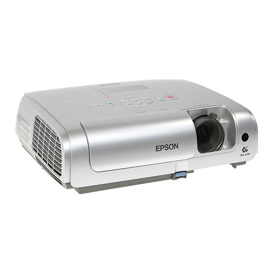
EMP-S4 1.2 Components, Connectors and Switches 1.2.1 External Components Lamp cover Security lock ( ) Control panel Focus ring Remote control light-receiving area Air exhaust vent Foot adjust lever A/V mute slide Front adjustable foot Figure 1-1. Main Unit Front... - Page 17 EMP-S4 Computer port S-Video port USB port Remote control light-receiving area Monitor Out port Video port Power inlet Speaker Rear adjustable foot Audio input Figure 1-3. Input and Output Connectors [Enter] button [Menu] button Automatically adjusts analogue RGB images from Displays and closes the configuration menu.
-
Page 18: Internal Components
EMP-S4 1.2.2 Internal Components Control Panel Cover Lens Frame Assy. Upper case unit MA Board Lamp Assy. Optical Engine Speaker IF unit TH Board Lamp lid detection switch Safety Switch Exhaust Fan Power Supply Fan Lamp Fan Power Supply Unit... -
Page 19: Remote Control
EMP-S4 1.2.3 Remote Control [E-Zoom] button( ) Enlarges parts of images without changing the size of the projection area. ) Reduces the part of images that have been Remote control light-emitting area enlarged using the ( ) button. Outputs remote control signals. -
Page 20: Specifications
EMP-S4 1.3 Specifications Projection System RGB Liquid Crystal Shutter Projection Projection Method Front/Rear/Ceiling Mount Size 0.5 inches with MLA Driving Method Poly-silicon TFT Active Matrix Pixel Number 480000 dots (800 x 600) x 3 Native Resolution SVGA Aspect Ratio 4 : 3... - Page 21 EMP-S4 Display Native 800 x 600 dots Performance Signal Type Separate signal Analog (0.7 V p-p, 75 Ω/ Mac 0.714 Vp-p, 75 Ω) Video Signal Separate (positive & negative, bi-polarity 2-5 Vpp) Input Signal Sync. Signal Composite (positive & negative, bi-polarity 2-5 Vpp) Sync-on-green (negative, 0.3 Vpp)
-
Page 22: Interface Specifications
EMP-S4 1.4 Interface Specifications Figure 1-7. 1.4.1 Computer Port Mini D-sub, 15 pin (input) Pin No. Signal Name Pin No. Signal Name (No pin) CN102 7513S-15G2-08 H Sync V Sync Mini D-sub, 15 pin (output) Pin No. Signal Name Pin No. -
Page 23: Usb Interface
EMP-S4 1.4.2 USB Interface USB-Type B CN503 UBB-4R-D14C Pin No. Signal Name VBUS 1.4.3 S-Video Interface Mini DIN4 pin CN100 TCS7708-012020 Pin No. Signal Name Y signal input C signal input SEIKO EPSON 1-11 Revision:B... -
Page 24: Cvbs Input Interface/Audio Input Interface
EMP-S4 1.4.4 CVBS Input Interface/Audio Input Interface RCA pin jack x 3 J101 YKC21-4098N Pin No. Signal Name CVBS SEIKO EPSON 1-12 Revision:B... -
Page 25: External Views
EMP-S4 1.5 External Views Unit: mm Figure 1-8. External Dimensions SEIKO EPSON 1-13 Revision:B... - Page 26 EMP-S4 Unit: Inch Figure 1-9. External Dimensions SEIKO EPSON 1-14 Revision:B...
-
Page 27: Chapter 2 Theory Of Operation
Chapter 2 Theory of Operation... -
Page 28: Hardware Overview
EMP-S4 2.1 Hardware Overview The hardware for the EMP-S4 can basically be divided into two sections: the optical engine and the circuit system. This section of the manual describes functions of the major hardware components. The components and unit in the dotted frame shown in the diagram below make up an optical engine and MA Board Kit, which is provided as one part. -
Page 29: Component Connection Diagram
EMP-S4 2.1.1 Component Connection Diagram The connectors for the components and Main (MA) board are shown in the following diagram. Photo Interrupter CN704 CN705 CN300 CN504 CN500 CN502 CN1400 CN100 CN101 CN1800 CN503 CN103 CN102 Lamp Fan Figure 2-2. MA Board Connectors... -
Page 30: Control Circuitry
EMP-S4 2.1.2 Control Circuitry The control circuits are illustrated in the following block diagram. Figure 2-3. Control Circuit Block Diagram SEIKO EPSON Revision:B... -
Page 31: Optical Engine
EMP-S4 2.2 Optical Engine The optical system consists of four components: the Lamp Assys., the Light Guide Unit, the Panel-on-Prism (POP) Unit, and the projection lens. These four components together are called the Optical Engine. Projection lens (focus) Light Valve (B) - Page 32 EMP-S4 C H E C K The Lamp Assy., Light Guide Unit, POP Unit, and Projection Lens together P O I N T make up the Optical Engine. These components are assembled and adjusted together at the factory, and are not available as separate service parts.
-
Page 33: Lamp Assy
EMP-S4 2.2.1 Lamp Assy. The Lamp Assy. is comprised of the Lamp (170W) and Ballast Power Supply Connector. The Ballast Power Supply Connector is used to supply the AC voltage from the ballast unit for driving the lamp. The lead wires are connected to the lamp. -
Page 34: Ma Board
EMP-S4 2.3 MA Board The MA board processes the core circuit controls for the projector, including interface control, operation panel control, temperature sensor circuit and fan control, ballast power supply control and the Infrared RC board interface. The MA board also contains an imaging processor (PW465), EEPROM, digitizers (ADC and video decoder), and SRAM memory. -
Page 35: Overview Of Operation
EMP-S4 2.3.2 Overview of Operation Digitalization control of the picture signal Converts the analog RGB image signals input from Computer/Component Video port from analog to digital form. Frequency transformation control Transforms the picture signal into the appropriate signals to drive the R, G and B LCD panels. -
Page 36: Interface Connectors
EMP-S4 2.4 Interface Connectors The MA board includes interface connectors for external devices such as video equipment. The MA board is equipped with the following connectors. Computer port S-Video port USB port Remote control Monitor Out port light-receiving area Video port Audio input Figure 2-10. -
Page 37: Power Supply Ballast Unit
EMP-S4 2.5 Power Supply Ballast Unit The Power Supply Ballast Unit contains the power supply/ballast section, power supply filter and the AC cord socket. The power supply/ballast section re-regulates the DC power supply that comes from the AC inlet and power supply filter in order to generate the AC power supply 170W for the lamps. -
Page 38: Overview Of Operation
EMP-S4 2.5.2 Overview of Operation The output cable of the power supply unit is connected to CN2000 on the MA board. It allows the following voltages and signals to be transmitted. • DC output • The power supply On/Off signal (PWON) -
Page 39: Connector Cn2000 Pin Layout
EMP-S4 2.5.3 Connector CN2000 Pin Layout Figure 2-14. Power Supply Connector (connected to CN2000 on the MA board) Pinout Definition Pin No. Signal name PFCON +5 V_T +5 V_T +5 V_T +7 V +13 V +18 V SEIKO EPSON 2-13... -
Page 40: Rc Board Assembly
EMP-S4 2.6 RC Board Assembly The Remote Control (RC) board is equipped with sensors that detect (receive) infrared signals transmitted from the remote control. The two RC IR sensors are mounted on the front and rear of the projector. Front IR Receiver Sensor... -
Page 41: Speaker
EMP-S4 2.7 Speaker The projector has a single 1 W built-in speaker that is at the rear of the projector. It can be used for monaural output of the sound that is input to the projector from a host computer or video source. -
Page 42: Temperature Control
EMP-S4 2.8 Temperature Control 2.8.1 Sensors and Switches This projector is equipped with the devices shown in the table below in order to protect the safety of the operator and maintain general safety with regard to the projector itself by preventing abnormalities in operation. - Page 43 EMP-S4 TH Board The TH Board is attached to the Inner Exhaust Duct to detect the temperature of the lamp section. To prevent damage to the surrounding components from overheating, the power save controller on the MA board first provides a warning indication through the temperature indicator LED, and stops the output of the ballast when the temperature rises above a given level.
-
Page 44: Fan Operation
EMP-S4 Thermistor and Temperature Sensor Operation Analog/Digital converters in IC104 on the MA board detect the temperatures of the Optical Engine and Power Supply sections by means of the two Lamp Thermistors at intervals of 1 second. Based on the measurement results, the CPU controls fan operations and power supply shutdown operations as necessary. - Page 45 EMP-S4 PW190 PW190 -05L -05L DAC0 DAC1 DAC2 DAC3 Intake Fan 1 FANDET0 FANAJST1 FANON1 Intake Fan 2 FANDET1 Exhaust Fan FANAJST2 FANON2 FANDET2 Power Supply Fan FANAJST3 FANON3 FANDET3 Lamp Fan FANAJST4 FANON4 FANDET4 Figure 2-23. Fan Control Circuit Block...
- Page 46 EMP-S4 Operation Control The MA board is connected to the Lamp Thermistor. The driver CPU controls the operation of the five fans, Intake fan 1, Intake fan 2, Exhaust fan, Power Supply fan and Lamp Fan, based on the temperatures detected by the thermistor.
-
Page 47: Led Indicators
EMP-S4 2.9 LED Indicators The SW board has three LEDs that indicate the operating status of the projector. The status indicators are located on the upper case unit. Temp indicator Lamp indicator Power indicator Figure 2-24. Status Indicator LEDs Location The following tables show what the indicators mean and how to remedy any problem indicated. - Page 48 EMP-S4 Indicator Status Projector Status Problem and Remedy Lamp problem Check that the lamp is not cracked and that the air filter Power Lamp timer and air intake vent are clear. • Remove the lamp and check if it is cracked.
-
Page 49: Chapter 3 Troubleshooting
Chapter 3 Troubleshooting... -
Page 50: Before Carrying Out Troubleshooting
EMP-S4 3.1 Before Carrying Out Troubleshooting • If repairs involving the replacement of parts or components have been carried out, always be sure to re-check whether the replacement parts themselves are operating correctly or not in order to determine whether the problem is the result of something such as a loose connec- tor. -
Page 51: Overview
EMP-S4 3.2 Overview Check the nature of the problem using the following flow diagram, and then proceed to the corresponding flow chart (on the following pages). START Exterior Check Check for any external abnormalities, such as a damaged case. Internal Cable Check Remove the Upper Case unit and check the cable connectors on the MA Board. -
Page 52: Exterior Check
EMP-S4 3.2.1 Exterior Check START There should be no damage, deformation or cracking due to external force. Upper Case Unit The Lower Case should be installed correctly. The remote signal receiver should be clean and free from foreign materials. The Cover Lens Holder should be correctly installed. -
Page 53: Internal Cable Check
EMP-S4 3.2.2 Internal Cable Check Turn off the power and disconnect the power cable before you begin the following connector checks. See Figure 2-2 on page 2-3 for the location of the MA Board connectors. START Upper Case Unit Removal... -
Page 54: Power Supply On/Off
EMP-S4 3.2.3 Power Supply On/Off START Power cord connection. Replace the Power Supply Is the indicator lit orange? Ballast Unit. Press the [Power] button on Press the [Power] button the control panel. Does the on the remote control. indicator flash green? - Page 55 EMP-S4 (Continued from previous page) Is the lamp turned on? Replace the Optical Engine and MA Board. Press the [Power] button to turn the power off. Replace the Optical Engine Does the indicator and MA Board. flash orange? Does the...
-
Page 56: Image Display And Quality
EMP-S4 3.2.4 Image Display and Quality The image quality can also be affected by condensation or by a dirty lens. C A U T I O N If condensation forms, the problem will correct itself naturally if the projector is left to stand for a while. - Page 57 EMP-S4 (Continued from previous page) Is the image quality good? Connect external devices to all the interfaces. Connect the host computer to the Computer 1. Press the [Menu] connectors and display button. an image. Connect a source to the 2. Select the "Image"...
-
Page 58: Audio Output
EMP-S4 3.2.5 Audio Output START Can the volume be adjusted? Connect the audio input connector and host computer. Press the [Source] button to select the corresponding input source, and output sound from the Replace the Optical Engine and internal speaker. -
Page 59: Control Panel
EMP-S4 3.2.6 Control Panel START Does pressing the [Power] button turn the power on and off? Ye s Does pressing the [Menu] button display the menu? Ye s Does pressing the [Source] button switch the input source? Ye s Does pressing the [Help] button show the... -
Page 60: Remote Control Operation
EMP-S4 3.2.7 Remote Control Operation START Does the remote control Do all buttons operate Can the power be turned work 20 ft. (6 m) away normally? on and off using the from the front or rear of remote control? the projector? Replace the remote control. -
Page 61: A/V Mute Slide
EMP-S4 3.2.8 A/V mute slide START Does opening/closing the A/V mute slide activate or deactivate A/V Mute? Replace the Photo Interrupter cable. Does opening/closing the A/V mute slide activate or deactivate A/V Mute? Replace the Photo Interrupter. Does opening/closing the A/V mute slide activate or deactivate A/V Mute? Replace the Optical Engine and MA Board. -
Page 62: Other
EMP-S4 3.2.9 Other START Is the projector making Check for any objects around the Exhaust Fan, Intake Fan and Power Supply Fan. abnormal noise? The cause might be a malfunction of the power supply unit (pulse transformer vibration, etc.). Is the projector overheating? Malfunction of the Lamp Thermistor or Safety Switch. -
Page 63: Chapter 4 Disassembly/Assembly
Chapter 4 Disassembly/Assembly... -
Page 64: Overview
4.1 Overview This chapter describes the procedures for disassembling and assembling the main components of the EMP-S4 projector. Unless otherwise specified, reassembly is the reverse of the disas- sembly procedure. Read the precautions described in the next section before starting. - Page 65 Use static discharge equipment such as anti-static wrist straps when accessing internal components to protect sensitive electronic components and circuitry. Do not use second source ICs or other components not approved by Epson. They could cause damage to the Epson product or could void the Epson warranty.
-
Page 66: Tools And Equipment
EMP-S4 4.1.2 Tools and Equipment The tools and equipment in the following table will be needed. All are commercially available, and should be made ready beforehand. Table 4-1. Tools Needed Name Application Phillips screwdriver No. 0 Disassembling the Focus ring Disassembling the outer case and inner Phillips screwdriver No. -
Page 67: Projector-Specific Service Precautions
EMP-S4 4.1.3 Projector-Specific Service Precautions C H E C K The Optical Engine and Main (MA) Board are paired together as a single service P O I N T part. Neither is available separately. For service that requires the replacement of either the MA Board or the Optical Engine, both components must be replaced together. -
Page 68: Projector Disassembly And Assembly
EMP-S4 4.2 Projector Disassembly and Assembly The general disassembly procedure for the EMP-S4 projectors is illustrated below. Except where indicated separately, all reassembly should be carried out by following the disassembly procedures in reverse. Detailed disassembly procedures for each component are given in Sec- tions 4.2.1 to 4.2.20,... - Page 69 After Service Part List in the SPI (Service Part Information). Table 4-2. Part Names given in the SPI Official Name used in SPI Names used this Chapter MODEL NAME PLATE;PowerLiteS4 EMP-S4 Model Name Plate Optical Engine and MAB set Optical Engine LAMP UNIT FOR AS CASE, LOWER...
- Page 70 EMP-S4 Table 4-2. Part Names given in the SPI Official Name used in SPI Names used this Chapter LENS,LED LED Lens PRINTED CIRCUIT BOARD ASSEMBLY;SW_R2 SW Board Assy. CABLE,SW;Au SW Cable, Au LID ASSY.,LAMP Lamp Lid Assy. SEIKO EPSON Revision:B...
-
Page 71: Removing The Model Name Plate
EMP-S4 4.2.1 Removing the Model Name Plate Remove the EMP-S4 Model Name Plate. 4.2.2 Removing the Lamp Lid Assy and LAMP UNIT FOR AS 1. Remove the screw that secures the Lamp Lid Assy, and remove the Lamp Lid Assy. -
Page 72: Removing The Front Foot Unit
EMP-S4 4.2.4 Removing the Front Foot Unit 1. Press a screwdriver or similar tool into the small slot beside the Front Foot Unit, and take out the Front Foot Unit. Front Foot Unit Figure 4-4. 4.2.5 Removing the Air Filter Frame and Air Filter A 1. -
Page 73: Removing The Upper Case
EMP-S4 4.2.6 Removing the Upper Case 1. Remove the 7 (C.B.P-TITE, 3x10, F/ZB-3C) screws that secure the Upper Case Unit. Figure 4-6. 2. Carefully lift the front of the Upper Case taking care not to pull the two cables connected to the Upper Case. - Page 74 EMP-S4 3. Unlock connector CN502 on the MA Board and disconnect the Control Panel Cable and SW cable. CN502 Locked CN502 Unlocked Figure 4-8. SEIKO EPSON 4-12 Revision:B...
-
Page 75: Removing The Rc Filter, Sw Light Shade Sheet B, Sw Board Assy,Sw Cable Au, Sw Button, And Led Lens
EMP-S4 4.2.7 Removing the RC filter, SW Light Shade Sheet B, SW Board Assy, SW Cable Au, SW Button, and LED Lens 1. Detach the RC Filter from the Upper Case. 2. Remove the SW Light Shade Sheet B from the SW Board Assy. - Page 76 EMP-S4 After connecting the SW Cable Au, aslant to fold and secure it with a piece of C A U T I O N heat resistant tape as shown in Figure 4-10. Make sure that the fold is kept 1 cm away from the SW Board Assy.
- Page 77 EMP-S4 The SW Cable and the SW Cable Au should be routed as shown in Figure 4- C A U T I O N cable sw, Au cable sw Figure 4-12. SEIKO EPSON 4-15 Revision:B...
-
Page 78: Removing The Cover Lens Holder, Cover Lens Unit, Cover Lens Sheet, Cover Lens Frame, Photo Interrupter, Cover Lens Guide, Lamp Lid Latch Springand And Sw Cable
EMP-S4 4.2.8 Removing the Cover Lens Holder, Cover Lens Unit, Cover Lens Sheet, Cover Lens Frame, Photo Interrupter, Cover Lens Guide, Lamp Lid Latch Springand and SW Cable. 1. Remove a (C.C.P-TITE SCREW, 3x8, F/ZN-3C) screw that secures the Cover Lens Unit, and remove the Cover Lens Holder and the Lens Cover from the Upper Case E. - Page 79 EMP-S4 3. Remove the 2 (C.C.P-TITE SCREW, 3x8, F/ZN-3C) screws that secure the Cover Lens Frame, and remove the Cover Lens Frame from the Upper Case E. 4. Remove the Photo Interrupterthe, the Cover Lens Guide and the Lamp Lid Latch Spring from the Cover Lens Frame.
- Page 80 EMP-S4 After replacing the Photo Interrupter, always perform operation check as C A U T I O N described below. 1). Turn the projector on leaving the Cover Lens open. 2). After confirming that the blue image (default) is displpayed, close the Cover Lens as shown in Figure 4-16.
-
Page 81: Removing The Ma Board Assy
EMP-S4 4.2.9 Removing the MA Board Assy. 1. Unlock the connectors of the Light Valve R/G/B connection cables. Light Valve R Locked Light Valve B Unlocked Light Valve G Figure 4-17. 2. Disconnect the Light Valve R/G/B connection cables and 10 cable connectors that are connected to the MA Board. - Page 82 EMP-S4 3. Remove the EMI Control Sheet from the MA Board Assy. 4. Remove the (C.C., 3x6, F/ZN-3C) screw to remove the MA Board Assy. EMI Control Sheet MA Board Assy. Figure 4-19. When installing the MA Board Assy, pay attention to the followings.
- Page 83 EMP-S4 2). Route the Power Supply Fan Cable as shown in Figure 4-21, and press into C A U T I O N the cable under the MA Board as far as it will go. Power Supply Fan Cable Figure 4-21.
- Page 84 EMP-S4 4). Route the power cord as shown in Figure 4-23, and secure the cable with a C A U T I O N heat-resistant tape. Gently squeeze the Power Supply Ballast Cable into the Power Supply Unit. Heat-Resistant Tape...
-
Page 85: Removing The If Case Set, Rc Filter, And Sw Light Shade Sheet B
EMP-S4 4.2.10 Removing the IF Case Set, RC Filter, and SW Light Shade Sheet B 1. Remove the SW Light Shade Sheet B from the IF Case Set. 2. Remove the 2 (C.B.P-TITE, 3x10, F/ZB-3C) screws that secure the IF Case Set, disconnect the Speaker Cable from connector CN1800 on the MA Board, and remove the IF Case Set from the MA Board Assy. -
Page 86: Removing The Ma Plate
EMP-S4 4.2.11 Removing the MA Plate 1. Remove the 2 (C.B.P-TITE, 3x10, F/ZB-3C) screws that secure the RCA connector, and the 4 (1/4-40x1/4, H.H., F/NI, O) screws that secure D-sub 15 Pin connectors. 2. Remove the 2 (C.C., 3x6, F/ZN-3C) screws that secure the MA Plate to the MA Board, and remove the MA Plate from the MA Board Assy. -
Page 87: Removing The Optical Engine
EMP-S4 4.2.12 Removing the Optical Engine 1. Remove the four (C.B.P-TITE SCREW, 3x10, F/ZB-3C) screws that secure the Optical Engine to the projector, and remove the Optical Engine. Screw Screw Screw Screw Figure 4-26. 4.2.13 Removing the Focus Ring 1. Remove the three (C.P.TYPE1 B-TITET-A. SCREW, 2x6, F/ZB-3C) screws that secure the Focus Ring, and remove the Focus Ring from the Projection Lens. -
Page 88: Projection Lens
EMP-S4 4.2.14 Projection Lens 1. Remove the four (C.P.(S-P1)SCREW,3x10,F/ZN-3C) screws that secure the Projection Lens, and remove the Projection Lens from the Optical Engine. 2. Remove the (H.N.-3, F/ZN-3C) screw nut from the Optical Engine. Optical Engine Projection Lens Figure 4-28. -
Page 89: Removing The Rc Board Assy, Rc Cable B, Safety Switch, Intake Duct, Intake Fan, And Intake Fan Sheet
EMP-S4 4.2.15 Removing the RC Board Assy, RC Cable B, Safety Switch, Intake Duct, Intake Fan, and Intake Fan Sheet 1. Remove the RC Board Assy, and disconnect the RC Cable B from the RC Board Assy. 2. Remove the (C.C.P-TITE, 3x8, F/ZN-3C) screw that secures the Safety Switch, and remove the Safety Switch from the Inner Exhaust Duct. - Page 90 EMP-S4 Route the AC Inlet Cable as shown in the figure below, and secure the ferrite C A U T I O N core on the tab of the Lower Case. Ferrite core Figure 4-30. SEIKO EPSON 4-28 Revision:B...
-
Page 91: Removing The Lamp Duct And Lamp Fan B
EMP-S4 4.2.16 Removing the Lamp Duct and Lamp Fan B 1. Remove the two (C.B.P-TITE SCREW, 3x10, F/ZB-3C) screws that secure the Lamp Duct, and remove the Lamp Duct. 2. Remove the Lamp Fan B from the Lower Case. Lamp Duct Lamp Fan, B Figure 4-31. -
Page 92: Removing The Exhaust Fan Set, Outer Exhaust Duct, And Exhaust Fan B
EMP-S4 4.2.17 Removing the Exhaust Fan Set, Outer Exhaust Duct, and Exhaust Fan B 1. Remove the (C.B.P-TITE, 3x10, F/ZB-3C) screw that secures the Exhaust Fan Set and remove it. Exhaust Fan Set Figure 4-32. When installing the cable of both the Lamp Lid Detection Switch and the C A U T I O N Exhaust Fan, route them as shown in Figure 4-33. - Page 93 EMP-S4 When installing the Ballast Cable, route the cable and move the ferrite core C A U T I O N into the position as shown in Figure 4-34. Ballast Cable Ferrite Core Figure 4-34. 2. Remove the two (C.B.P-TITE SCREW, 3x30, F/ZN-3C) screws that secure the Exhaust Fan B, and remove the Outer Exhaust Duct from the Exhaust Fan Set.
-
Page 94: Removing The Th Board Assy, Cable Rcr Fif, Lamp Lid Detection Switch, And Inner Exhaust Duct
EMP-S4 4.2.18 Removing the TH Board Assy, Cable RCR FIF, Lamp Lid Detection Switch, and Inner Exhaust Duct 1. Remove the (C.C.P-TITE, 2x12, F/ZN-3C) screw that secure the Lamp Lid Detection Switch, and remove the Lamp Lid Detection Switch from the Inner Exhaust Duct. -
Page 95: Removing The Power Supply Fan B And Power Supply Assy
EMP-S4 4.2.19 Removing the Power Supply Fan B and Power Supply Assy 1. Remove the two (C.P.(S-P2)SCREW, 3x20, F/ZN-3C) screws that secure the Power Supply Fan B, and remove the Power Supply Fan B from the Power Supply Assy. Power Supply Fan, B Figure 4-37. -
Page 96: Removing The Lamp Shield Plate, Power Supply Filter, And Lower Case
EMP-S4 4.2.20 Removing the Lamp Shield Plate, Power Supply Filter, and Lower Case 1. Remove the Lamp Shield Plate from the Lower Case. Lamp Shield Plate Power Supply Filter Lower Case Figure 4-39. SEIKO EPSON 4-34 Revision:B... -
Page 97: Chapter 5 Appendix
Chapter 5 Appendix... -
Page 98: As (After Service) Menu
EMP-S4 The contents of this chapter are for use only by Epson Authorized Servicers, and C A U T I O N are not to be disclosed to others without the express written consent of Epson. 5.1 AS (After Service) Menu The AS (After Service) menu provides information and settings that are not displayed on the standard menu. -
Page 99: Initializing (Resetting) The As Menu Values
EMP-S4 When the video source is Video type, the following screen is displayed. Computer Computer Video Signal Video Signal : ---- : ---- (No Signal (No Signal Total Operation Time Total Operation Time Lamp Op. Time (C) Lamp Op. Time (C) -
Page 100: Software Dip Switches
EMP-S4 5.1.3 Software DIP Switches Some software DIP-switch settings are only accessible from the AS menu. To display the DIP- SW Setting Menu, do the following operation. 1. Press button on the remote control for at least 5 seconds. Menu 2. - Page 101 EMP-S4 DIP-SW Default Function Setting Value Note Setting Configurable by 1 minute, 1-255 Time to sleep mode minutes Default: 30 Minutes Time to sleep mode Time to sleep mode Time to sleep mode Time to sleep mode Time to sleep mode...
- Page 102 EMP-S4 SEIKO EPSON Revision:B...