Table of Contents
Advertisement
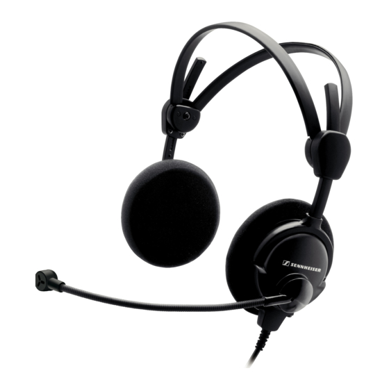
Short description
This headset features dynamic, open headphones. The noise-compensating
microphone ensures excellent speech transmission even in noisy
environments. Designed for air traffic control, intercom systems and other
communication purposes.
Features
•
™
ActiveGard
(not HME 46-31 and HMD 46-31)
•
"Flip-away" earcup
•
Automatic two-piece headband
•
Flexible microphone boom can be worn on either left or right-hand side
•
Single-sided cable
•
Comfortable wearing earpads
•
PTT button integrated in the cable (HME/HMD 46-3PTT-x only)
Service manual
Revision
02/2008
Sennheiser electronic GmbH & Co. KG • 30900 Wedemark, Germany
Phone: +49 (5130) 600 0 • Fax: +49 (5130) 600 300
Air Traffic Control
HME 46-3
HMD 46-3
Product variants
500857
HME 46-3
500467
HME 46-3-6
500874
HME 46-3PTT-M
500468
HME 46-3PTT-6
500469
HME 46-3PTT-L
502172
HME 46-3PTT-LA
500851
HME 46-ATC
502484
HME 46-31
500849
HMD 46-3
500466
HMD 46-3-6
500873
HMD 46-3PTT-M
502483
HMD 46-31
502594
HMD 46-3(5)
Cable variants
500836
-6
502360
-7
502365
-L
500844
-PTT-6
502418
-PTT-6-1
500845
-PTT-L
502187
-PTT-LA
500930
-D-3PTT-M
500931
-E-3PTT-M
SA 070401
1/25
Advertisement
Table of Contents

Related Manuals for Sennheiser HME 46-3


Summary of Contents for Sennheiser HME 46-3
- Page 1 Flexible microphone boom can be worn on either left or right-hand side • Single-sided cable • Comfortable wearing earpads • PTT button integrated in the cable (HME/HMD 46-3PTT-x only) Sennheiser electronic GmbH & Co. KG • 30900 Wedemark, Germany 1/25 Phone: +49 (5130) 600 0 • Fax: +49 (5130) 600 300...
- Page 2 Otherwise, the person who has altered the product is liable for any consequential damage. repairs/exchanges The following instructions for overhaul and testing must be followed. In case of unusual problems please contact your Sennheiser distributor. HME 46-3, HMD 46-3 2/25 02/2008...
-
Page 3: Table Of Contents
5.2.1 Audio testing the headset with cable ............11 5.2.2 Operational testing of the pre-polarized microphone at the headset with cable (HME 46-3-x only) ..........11 5.2.3 Testing of the dynamic microphone at the headset with cable (HMD 46-3-x only)..........12 5.2.4 Operational testing of the headset cables ............ -
Page 4: Outline Dimension
0.50 m 0.30 m -PTT-L, -PTT-6 1.50 m 1.00 m -PTT-6-1 0.80 m Cable type Complete cable length -PTT-6, 1.85 m -PTT-6-1, -PTT-L 2.30 m -PTT-LA 2.45 m -E/D-3PTT-M 2.00 m -ATC / -L HME 46-3, HMD 46-3 02/2008 5/25... -
Page 5: Technical Data
Transducer principle _____________________ dynamic, noise compensating Frequency response______________________ 100 to 12.000 Hz Output voltage _________________________ 0.125 mV/Pa Impedance ____________________________ 5 ohms Microphone of HME 46-3 (with preamplifier) Type _______________________________ MKE 46 Transducer principle _____________________ pre-polarized condenser microphone, noise compensating Frequency response______________________ 350 to 6.000 Hz... -
Page 6: Disassembly
2. Remove the cable from the cable holder (110). Disassembly of the cap Reference: see “Exploded view HME 46-3 / HMD 46-3”, page 21 1. Remove the earpad (90) from the relevant cap (20 or -25). 2. Lift the sides of the discs (80), now the screws (70) are visible or remove the discs (80) from the caps (20 or -25) completely if necessary. -
Page 7: Disassembly Of The Microphone Arm
Disassembly of the microphone arm Reference: see “Exploded view HME 46-3 / HMD 46-3”, page 21 or see “Exploded view of the cap, microphone side”, page 24. 1. Rotate the microphone arm (100 or -105) to the side position if necessary (see figure below). -
Page 8: Assembly
Reference: • see “Exploded view HME 46-3 / HMD 46-3”, page 21. 1. Attach the relevant cap (20 or -25) to the headband (10). 2. Solder the relevant leads of the split headband cable to the PCBs (TP1 to TP4), see “Printed circuit boards”, page 19 and see “Block diagram”, page 20. -
Page 9: Assembly Of The Cable To The Headset
2. Fasten the screws of the system cable with a torque of 25 Ncm 3 Ncm. Assembly of the microphone arm Reference: see “Exploded view HME 46-3 / HMD 46-3”, page 21. 1. At the inside of the microphone arm fixing is a latch . Firstly set this latch at the right socket position of the cap (20). -
Page 10: Testing And Fault Isolation
3. Listen to the audio output signal. No distortion should be audible. B. Visual testing 1. For detailed visual testing please use the ossiloscope, see “Microphone test setup according to RTCA/DO- 214”, page 14. HME 46-3, HMD 46-3 02/2008 11/25... -
Page 11: Testing Of The Dynamic Microphone At The Headset With Cable (Hmd 46-3-X Only)
1. Set the sine wave generator to 100 mVeff ± 5 mV with a signal of 1 kHz to the PCB. Set a signal to TP8 (+) and TP9 (-), see “Printed circuit boards”, page 19. 2. In the headphones, the 1 kHz tone must be audible. HME 46-3, HMD 46-3 12/25 02/2008... -
Page 12: Testing Of The Activegard™ Of The Pcb (Not Hmd/E 46-31)
8 dBV. The PCB with ±5 mV 30 to 40 mV loudspeaker works correctly. Speaker´s voice Headphone Microphone connector connector output input output Oscilloscope Audio amplifier Figure 1 Operational test of the dynamic microphone HME 46-3, HMD 46-3 02/2008 13/25... - Page 13 Audio Lo right screen not connected orange Screen Audio Hi left bridge Audio Lo left Microphone Hi blue Microphone Lo white Bridge to pin 10 brown Bridge to pin 9 Figure 3 Cable connector´s pin alignment HME 46-3, HMD 46-3 14/25 02/2008...
-
Page 14: Wiring Diagrams
Wiring diagrams Wiring diagram for cable -E-3PTT-M, -D-3PTT-M HME 46-3, HMD 46-3 02/2008 15/25... -
Page 15: Wiring Diagram For Cable -Ptt-L
Wiring diagram for cable -PTT-L HME 46-3, HMD 46-3 16/25 02/2008... -
Page 16: Wiring Diagram For Cable -Ptt-6
Wiring diagram for cable -PTT-6 HME 46-3, HMD 46-3 02/2008 17/25... -
Page 17: Wiring Diagram For Cable -Ptt-La
Wiring diagram for cable -PTT-LA HME 46-3, HMD 46-3 18/25 02/2008... -
Page 18: Printed Circuit Boards
Printed circuit boards HME 46-3, HMD 46-3 02/2008 19/25... -
Page 19: Block Diagram
Block diagram HME 46-3, HMD 46-3 20/25 02/2008... -
Page 20: Exploded Views With Spare Part Lists
Exploded views with spare part lists Exploded view HME 46-3 / HMD 46-3 HME 46-3, HMD 46-3 02/2008 21/25... -
Page 21: Spare Part List For Hme 46
90 515295 EARPADS, 1 PAIR -95 515296 EARPADS, 100 PAIRS 100 528135 MICROPHONE ARM MD 46-413 STANDARD -105 528154 MICROPHONE ARM MD 46-413_5 OHMS 110 093675 CABLE HOLDER 120 528106 LABEL - ITEM NOT ILLUSTRATED HME 46-3, HMD 46-3 22/25 02/2008... -
Page 22: Exploded View Of The System Module
10 515642 20 515643 PCB ASSEMBLY MICROPHONE SIDE FOR HME/D 46-3 -20A 528156 PCB ASSEMBLY MICROPHONE SIDE FOR HME/D 46-31 (WITHOUT ACTIVEGARD) 30 515002 LEAD BROWN 40 515003 LEAD ORANGE - ITEM NOT ILLUSTRATED HME 46-3, HMD 46-3 02/2008 23/25... -
Page 23: Exploded View Of The Cap, Microphone Side
Exploded view of the cap, microphone side cap of microphone side microphone arm Spare part list of the cap, microphone side FIG. ITEM PART NUMBER NOMENCLATURE UNITS PER ASSY 10 087509 THREADED PIN - ITEM NOT ILLUSTRATED HME 46-3, HMD 46-3 24/25 02/2008... -
Page 24: Exploded View Cable -Ptt-X
100 515486 CABLE -PTT-6, 1.5 M 100 515479 CABLE -PTT-6-1, 0.8 M 100 515486 CABLE -PTT-L, 1.5 M 100 515470 CABLE -PTT-LA, 0.5 M 100 515479 CABLE -E/D-3PTT-M, 0.8 M - ITEM NOT ILLUSTRATED HME 46-3, HMD 46-3 02/2008 25/25...