Table of Contents
Advertisement
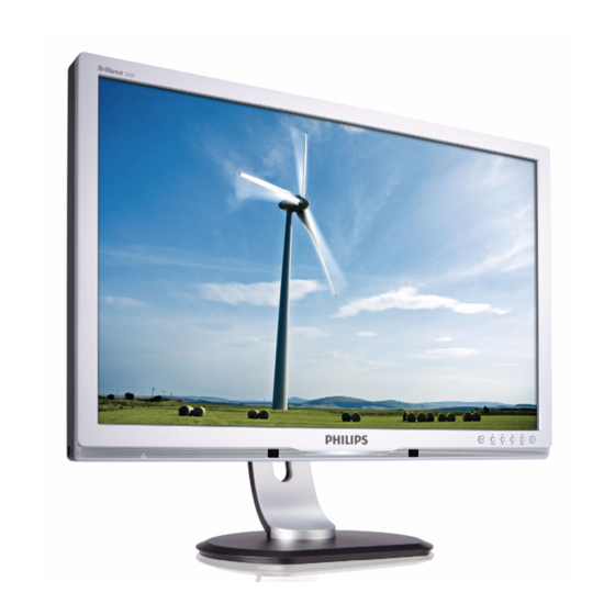
24 inch TFT WUXGA LCD Colour Monitor
Description
Important Safety Notice--------------------------------------2
Technical Data-------------------------------------------------3
Installation-------------------------------------------------------4
Troubleshooting-----------------------------------------------5
On Screen Display-----------------------------------------6~7
Lock/unlock, Aging,Factory mode------------------------8
Mechanical Instructions ------------------------------10~13
Color adjustment --------------------------------------------14
F AQs (Frequently Asked Questions)--------------15~16
Electrical instruction ----------------------------------17~18
Service Tool-----------------------------------------------19~20
DDC Instructions & Serial Number -----------------21~27
DDC DATA -----------------------------------------------28~29
ANY PERSON ATTEMPTING TO SERVICE THIS CHASSIS MUST FAMILIARIZE HIMSELF WITH THE CHASSIS
AND BE AWARE OF THE NECESSARY SAFETY PRECAUTIONS TO BE USED WHEN SERVICING ELECTRONIC
EQUIPMENT CONTAINING HIGH VOL TAGES.
CAUTION: USE A SEPARATE ISOLATION TRANSFORMER FOR THIS UNIT WHEN SERVICING.
Published by Philips Consumer Lifestyle Copyright reserved Subject to modification
245P2ES/00
245P2ES/00(AP)
245P2EB/69
245P2EB/75
245P2EB/93
TABLE OF CONTENTS
Page
---------------------------------9
-------------------------30~32
SAFETY
REFER TO BACK COVER FOR IMPOR T ANT SAFETY GUIDELINES
Chassis:
Description
-
-----------------------------------33
Wiring Diagram---------------------------------------------34
Block Diagram-----------------------------------------------35
Scaler Diagram & C.B.A. -----------------------------36~44
Power Diagram & C.B.A. ----------------------------45~50
Control Diagram & C.B.A. ----------------------------51~52
USB Diagram & C.B.A. ---------------------------------55~57
IR Diagram & C.B.A. ------------------------------------58~59
TX Diagram & C.B.A. ------------------------------------60~61
General product specification-----------------------62~88
Exploded V iew -----------------------------------------------89
Spare/
Recommended P
PCBA photos---------------------------------------------------91
Repair tips------------------------------------------------92~93
Repair Flow chart---------------------------------------94~96
Safety Test Requirments-----------------------------------97
NOTICE
JAug12 2010
MERIDIAN 2
Horizontal frequencies
30 - 8 3 kHz
Page
arts List------------------------90
GB
Advertisement
Chapters
Table of Contents

Related Manuals for Philips 245P2ES/00


Summary of Contents for Philips 245P2ES/00
-
Page 1: Table Of Contents
AND BE AWARE OF THE NECESSARY SAFETY PRECAUTIONS TO BE USED WHEN SERVICING ELECTRONIC EQUIPMENT CONTAINING HIGH VOL TAGES. CAUTION: USE A SEPARATE ISOLATION TRANSFORMER FOR THIS UNIT WHEN SERVICING. REFER TO BACK COVER FOR IMPOR T ANT SAFETY GUIDELINES Published by Philips Consumer Lifestyle Copyright reserved Subject to modification JAug12 2010... -
Page 2: Important Safety Notice
SERVICE MANUAL. recommended by Philips must f irst sati sfy himself thoroughly that neither his safety nor the saf e operation of the equipment will be jeopardized by the service method sel ected. -
Page 3: Technical Data
245P2 LCD Technical Data SEC panel Type NR. : SEC LTM24CT04 Resolution : 1920x1200 (WUXGA) Outside dimensions : 546.4 (H) x 350 (V) x 18.96 (D) Pitch ( mm ) : 0.27 PIN No. SIGNAL PIN No. SIGNAL DDC +3.3V or +5V Color pixel arrangement : RGB vertical stripes Green/ SOG Logic GND... -
Page 4: Installation
Front View Product Description Accessory Pack Unpack all the parts Connecting to Your PC 1) Connect the power cord to the back of the monitor firmly. (Philips has pre-connected VGA cable for the first installation.) *available for selective models Rear View... -
Page 5: Troubleshooting
245P2 LCD Troubleshooting... -
Page 6: On Screen Display
What is the On-Screen Display? On-Screen Display (OSD) is a feature in all Philips LCD monitors. It allows an end user to adjust screen performance or select functions of the monitors directly through an on-screen instruction window. A user friendly on screen display interface is shown as below : Basic and simple instruction on the control keys. - Page 7 245P2 LCD On-Screen Display The OSD Tree Below is an overall view of the structure of the On-Screen Display. You can use this as a reference when you want to work your way around the different adjustments later on.
- Page 8 245P2 LCD To lock/unlock OSD FUNCTION(User Mode) signal is 1680*1050vertical 60Hz. Slightly increase or The OSD function can be locked by pressing"OK"button(1) decrease the value until snowy noise completely disappear . for more than 10 seconds, the screen shows following windows for 4 seconds.
-
Page 9: Philips Pixel Defect Policy
Pixel Defect Tolerances In order to qualify for repair or replacement due to pixel defects during the warranty period, a TFT LCD panel in a Philips flat panel monitor must have Pixels and Sub pixels pixel or sub pixel defects exceeding the tolerances listed in the following A pixel, or picture element, is composed of three sub pixels in the primary tables. - Page 10 245P2 LCD Preparation before disassemble 1. Clean the room for disassemble 2. Identify the area for monitor 3. Check the position that the monitors be placed and the quantity of the monitor ;prepare the area for material flow; according to the actual condition plan the disassemble layout 4.
- Page 11 245P2 LCD Take off two pieces of aluminum foils on the left of monitor disassemble a screw on Screw-driver the audio board, tear off USB cable two pieces of acetic tapes, then draw the USB cable and the speaker cable which links the audio board Take off four pieces of aluminum foils, then draw...
- Page 12 245P2 LCD Please carefully use Tear off amber tape on two hands (one the FFC, then uplift the hand presses the locking-latch of Main-BKT and unlock the LVDS cable’s LVDS by using two hands housing, and at the (see note). same time another hand pulls out the LVDS cable.) for this...
- Page 13 245P2 LCD Pull out the cable of Notes: Pull the Power board connect upright Pull out the LVDS cable Notes: use one finger lift up the cover of connect ,and then pull the LVDS cable upright Disassemble the C/B: Screw-driver screw*3 Uplift the LED/B, and separate the boards and...
-
Page 14: Color Adjustment
245P2 LCD Color Adjustment Alignment procedure 1. Turn on the LCD monitor . 2. Turn on the Timing/pattern generator. See Fig.1 3. Preset LCD color Analyzer CA-1 10 -Remove the lens protective cover of probe CA-A30. -Set measuring/viewing selector to measuring position for reset analyzer .(zero calibration) as Fig.2 - Turn on the color analyzer (CA-1 10) -Press 0-CAL button to starting reset analyzer . -
Page 15: Faqs (Frequently Asked Questions)
4. Restart your computer and repeat step 2 and 3 to verify that your PC is set at 1920x1200@60Hz (24"). 5. Shut down your computer, disconnect your old monitor and reconnect your Philips LCD monitor. 6. Turn on your monitor and then turn on your PC. - Page 16 Q9: Can the Philips LCD Monitor be mounted on the wall? A: Yes. Philips LCD monitors have this optional feature. For standard VESA mount holes on the rear cover allows the user to mount the Philips monitor on most of the VESA standard arms or accessories. We recommend to contact your Philips sales representative for more information.
- Page 17 245P2 LCD 3.3.3. Factory preset modes (15 modes) Electrical characteristics Factory modes and preset modes are defined in the enclosed timing table file Interface signals 1.1. D-Sub Analog Input signal : Video, Hsync., Vsync Video : 0.7 Vp-p, input impedance, 75 ohm @DC Sync.
- Page 18 245P2 LCD White color adjustment There are three factory preset white color 9300K, 6500K, sRGB Apply full gray64 pattern, with brightness in 100 % position and the contrast control at 50 % position. The 1931 CIE Chromaticity (color triangle) diagram (x ,y) coordinate for the screen center should be: There are three factory preset white color 9300K, 6500K, sRGB.
-
Page 19: Service Tool
245P2 LCD Service tool-Hardware PCM code 12NC 5E.L8215.001 996510019769... - Page 20 245P2 LCD Service tool-Software FW writing tool: RTD tool V6.3 or V6.7 DDC writing tool: Q-EDID-V16...
- Page 21 245P2 LCD DDC Instructions DDC Data Re-programming In case the DDC data memory IC or main EEPROM which storage all factory settings were replaced due to a defect, the serial numbers have to be re-programmed "Analog DDC IC, Digital DDC IC & EEPROM". It is advised to re-soldered DDC IC and main EEPROM from the old board onto the new board if circuit board have been replaced, in this case the DDC data does not need to be re-programmed.
-
Page 22: Pin Assignments
245P2 LCD DDC Instructions 5. Connect and Mains cord to Monitor as shown in Fig.2. Fig.2 Pin assignments : A. 15-pin D-Sub Connector PIN No. SIGNAL PIN No. SIGNAL DDC +3.3V or +5V Green/ SOG Logic GND Blue Sense (GND) Sense (GND) Bi-directional data Cable Detect (GND) - Page 23 245P2 LCD DDC Instructions 6. Setup the Philips-IMS EDID Tools program Step 1: Open Q-EDID Software Q-EDID-V016 into your folder as shown in Fig.3. and Fig.4. Fig.3 Fig.4...
- Page 24 245P2 LCD DDC Instructions Step 2: Press “Open File” then choose LCD_Analog.ddc or LCD_DVI.ddc as shown in Fig. 5 . Fig.5...
- Page 25 245P2 LCD DDC Instructions Step 3 : Load DDC file success as shown in Fig. 6 . Fig.6 Step 4 : update Serial number and press enter to correct S/N number shown as Fig.7 . Fig.7...
- Page 26 245P2 LCD DDC Instructions Step 5 : Press “RUN” to write EDID and serial number shown as Fig.8 . Fig.8 Step 6 : EDID and serial number update success shown as Fig.9 Fig.9...
- Page 27 245P2 LCD DDC Instructions 8. Press Monitor Menu Key to check OSD Serial number is the same as PI-EDID write data as shown in Fig.10 Note: If not the same, please rewrite EDID S/N again. Fig.14 9 Turn off the monitor, exit the factory mode. Serial Number Definition...
-
Page 28: Ddc Data
00000020 = 12,50,54,BF,EF,80,D1,00,81,C0,81,40,95,00,95,0F,B3,00, 125054BF.EF80D100.81C08140.9500950F.B300A940. A9,40,01,01,28,3C,80,A0,70,B0,23,40,30,20, 0101283C.80A070B0.23403020 ......00000040 = 36,00,07,44,21,00,00,1A,00,00,00,FF,00,43,53,31,30,37,3 36000744.2100001A.000000FF.00435331.30373135.30 1,35,30,30,30,30,30,31,00,00,00,FC,00,50, 303030.30310000.00FC0050 ......00000060 = 68,69,6C,69,70,73,20,32,34,35,50,0A,00,00,00,FD,00,30, 68696C69.70732032.3435500A.000000FD.00305518.5 55,18,5E,15,00,0A,20,20,20,20,20,20,00,09 E15000A.20202020.20200009 Model name....Philips 245P Manufacturer..... Philips Plug and Play ID..PHL089E Serial number.... CS10715000001 Manufacture date..2010, ISO week 25 -------------------------... - Page 29 0,B3,40,01,01,28,3C,80,A0,70,B0,23,40,30,20, 0101283C.80A070B0.23403020 ......00000040 = 36,00,07,44,21,00,00,1A,00,00,00,FF,00,43,53,31,30,37 36000744.2100001A.000000FF.00435331.30373135.30 ,31,35,30,30,30,30,30,31,00,00,00,FC,00,50, 303030.30310000.00FC0050 ......00000060 = 68,69,6C,69,70,73,20,32,34,35,50,0A,00,00,00,FD,00,3 68696C69.70732032.3435500A.000000FD.00305518.5 0,55,18,5E,11,00,0A,20,20,20,20,20,20,00,F1 E11000A.20202020.202000F1 Monitor #1 [Real-time 0x0011] Model name....Philips 245P Manufacturer..... Philips Plug and Play ID..PHL089E Serial number.... CS10715000001 Manufacture date..2010, ISO week 25...
-
Page 30: Firmware Upgrade For Cpu
245P2 LCD Firmware Upgrade for CPU 1. Hardware Requirement: 1.1. I2C board x 1 (a.Print Board b. I2C Board) 1.2. DSUB VGA cables x 2 1.3. Printer cable (with one male connector and another female connector) x 1. 1.4. PC or Notebook with parallel (printer) port x1. Print 1.5 Check the Jumpers on the I2C circuit board (make sure J5/J6/J7/J8 are set at Pin 1 &... - Page 31 245P2 LCD Firmware Upgrade for CPU Link “I2C BD, Power cable and Signal cable 2. Software prepare DebugTool_V6.7_20090625.exe Step 1: Press RTD Tool Step 2: Choose “ IIC”, “RTD2122” and . Then, press “ISP”...
- Page 32 245P2 LCD Firmware Upgrade for CPU Step 3: Click the “BigBin” and Find the F/W 1. xxx.bin Step4: Choose “All” ,”0X94”, “Bin” and “Auto” Step5: Press to run the program Step6: Check result, If the words showed in red, need to run the program again...
-
Page 33: Failure Mode Of Panel
245P2 LCD Failure Mode Of Panel Quick reference for failure mode of LCD panel this page presents problems that could be made by LCD panel. It is not necessary to repair circuit board. Simply follow the mechanical Polarizer has bubbles instruction on this manual to eliminate failure by replace LCD panel. - Page 44 245P2 LCD S c aler Diagram...
-
Page 54: Led Diagram & C.b
245P2 LCD LED Diagram & C.B .A... - Page 59 245P2 LCD...
- Page 61 245P2 LCD...
-
Page 62: General Product Specification
Pole Lai Update Economy Brightness level set to 40% (P16) Net/Gross weight and container loading update (P21~23) Update SmartImage setting. (P13~14) Red : pending item Blue : change in this version 245P2 24W” Standard LCD Monitor 2010/08/02 PHILIPS 1 of 27... - Page 63 . SOG SUPPORT . TCO’5.0 . AUDIO SUPPORT . Windows Vista Premium Logo Certification . HDCP support for DVI inputs . POWER ON PHILIPS LOGO REQUIREMENT . WEEE REQUIREMENT . RoHS REQUIREMENT . POWER SENSOR SUPPORT . PIVOT FUNCTION SUPPORT 245P2 24W”...
- Page 64 UPPORT 3.13 EDID ....................11 3.14 H ................12 KEY DEFINITION 3.15 S ) ........... 12 MART CONTRAST YNAMIC CONTRAST RATIO 3.16 S ..................12 MART MAGE VISUAL CHARACTERISTICS................ 17 245P2 24W” Standard LCD Monitor 2010/08/02 PHILIPS 3 of 27...
- Page 65 SHT 191/SHT560 ) ..21 RODUCT DIMENSION EIGHT EFER TO HILIPS APPROVED 5.17 T ................21 RANSPORTATION 5.18 P SHT 560) ....... 21 ALLET ONTAINER LOADING EFER TO HILIPS APPROVED ENVIRONMENTAL CHARACTERISTICS ............22 245P2 24W” Standard LCD Monitor 2010/08/02 PHILIPS 4 of 27...
- Page 66 ISPLAY DISTURBANCES TO EXTERNAL ENVIRONMENT RELIABILITY ..................23 ..............23 ETWEEN AILURES QUALITY ASSURANCE REQUIREMENTS ............23 ................23 CCEPTANCE TEST PHILIPS’ FLAT PANEL MONITORS PIXEL DEFECT POLICY ........23 245P2 24W” Standard LCD Monitor 2010/08/02 PHILIPS 5 of 27...
-
Page 67: Foreword
30 minutes that brightness stability is optimal, and follow strictly after panel specification. PRODUCT PROFILE This display monitor unit is a color display monitor enclosed in PHILIPS styling cabinet which has an integrated tilt / high adjustment base. Type: TN Suppliers to offer the panel specification. -
Page 68: Electrical Characteristics
SIGNAL Green/ SOG Blue Sense (GND) Cable Detect (GND) Red GND Green GND Blue GND DDC +3.3V or +5V Logic GND Sense (GND) Bi-directional data H/H+V sync V-sync Data clock 245P2 24W” Standard LCD Monitor 2010/08/02 PHILIPS 7 of 27... -
Page 69: Timing Requirement
3.3 Timing requirement Factory Preset mode definition : 1. Perfect FOS (except PHASE) while presenting all required timings. 2. Required timings need to be specified in User's Manual Preset mode definition : 245P2 24W” Standard LCD Monitor 2010/08/02 PHILIPS 8 of 27... -
Page 70: General Product Specification
51 preset modes 3.3.2 Factory preset modes (15 modes) Factory modes and preset modes are defined in the enclosed timing table file Video timing mode (internal firmware support) 60Hz: 480p/720p/1080i/1080p 50Hz: 576p/720p/1080i/1080p 245P2 24W” Standard LCD Monitor 2010/08/02 PHILIPS 9 of 27... -
Page 71: Osd Behavior
OSD LANGUAGES 8 LANGUAGES OSD TREE POWER ON LOGO Power On Logo: Power On Show up Philips logo 3 seconds Change to input signal. This picture is reference only. The official drawing will send out by PM. -
Page 72: Power Management
Display Tune at least. 3.13 EDID Data for EDID & .inf file 1 User visible strings on .inf file Philips 245P (24inch Wide LCD MONITOR 245P2) 2 Manufacturer ID ( EDID data) 3 Product ID, "xxxx" 4 codes MSB(byte 12): 08... -
Page 73: Hot-Key Definition
A. 5 different modes are switched to next in the sequence from 1 to 5 then back to 1 while pressing this button: 1) Office Work 2) Image Viewing 3) Entertainment 4) Economic Economy 245P2 24W” Standard LCD Monitor 2010/08/02 PHILIPS 12 of 27... - Page 74 3.16.7 Profile Definitions (system integrators to input at design stages) A. Office Purpose: Design for general office application, like word processing, Spreadsheet and email. The screen is dominated by text. 245P2 24W” Standard LCD Monitor 2010/08/02 PHILIPS 13 of 27...
- Page 75 1. Dynamic contrast enhancement by histogram analysis (DLC) should be off. 2. Sharpness and color to be enhanced 75%. 3. Color temperature 6500°K 4. Brightness level sets to maximum. 5. Smart Response set to “Off”. (N/A for this model) 245P2 24W” Standard LCD Monitor 2010/08/02 PHILIPS 14 of 27...
- Page 76 1. This will follow user OSD setting. If any change by user, it will be saved. When switch back from other SmartImage profiles, it will go back to last saved setting. 2. Gamma Table is turn on to reduce bad color tracking. 245P2 24W” Standard LCD Monitor 2010/08/02 PHILIPS 15 of 27...
- Page 77 When demo mode is On, press 3 seconds or more to turn off the demo mode. When the demo mode is enabled, all the function key won’t be work until demo mode disabled. 245P2 24W” Standard LCD Monitor 2010/08/02 PHILIPS 16 of 27...
-
Page 78: Visual Characteristics
Measure YA. Then output Pattern 3 and measure YB. the cross talk value : ABS ( YA - YB ) X 100% < 1.5 % White color adjustment There are three factory preset white color 9300K, 6500K, sRGB 245P2 24W” Standard LCD Monitor 2010/08/02 PHILIPS 17 of 27... - Page 79 = 0.329 ± 0.006 sRGB x = 0.313 ± 0.006 PerfecTune II y = 0.329 ± 0.006 5000K x = 0.345 ± 0.006 PerfecTune II y = 0.357 ± 0.006 245P2 24W” Standard LCD Monitor 2010/08/02 PHILIPS 18 of 27...
- Page 80 Mechanical characteristics Cosmetic - Philips ID Mechanical data files - ProE files required Location of Philips logo - Per Philips make-up sheet Gap between panel and front bezel < 1.4mm (Typ.) + 0.3 (Tolerance) Location of Control icons - Per Philips Graphic sheet Color for resin/paint –...
- Page 81 “ ” 5.12 Texture/Glossing of housing The texture area and texture no should follow Philips make-up sheet. The exterior surfaces shall have a uniform texture. Philips must approve the mold texturing. Detail document for texture refer to “UN-D249”, “UN-D 600”.
- Page 82 245P2 LCD General Product Specification 5.16 Product dimension / Weight ( Refer to Philips approved SHT 191/SHT560 ) Unit dimension : 558.6 x 512.4 x 220 mm Packed unit dimension: 670*456*27 mm Net weight : 7.6 kg Gross weight : 10.5 kg 5.17...
- Page 83 Susceptibility of display to external environment Operating - Temperature : 0 to 40 degree C - Humidity : 80% max - Altitude : 0-3658m 245P2 24W” Standard LCD Monitor 2010/08/02 PHILIPS 22 of 27...
- Page 84 According to MIL-STD-1916D Control III level AQL: NA (Please also refer to annual quality agreement) Customer acceptance criteria: UAW0377/00 Philips’ Flat Panel Monitors Pixel Defect Policy Philips’ Flat Panel Monitors Pixel Defect Policy BRIGHT DOT DEFECTS ACCEPTABLE LEVEL MODEL 245P2...
- Page 85 Black dot defects within 20 mm circle* Total black dot defects of all type TOTAL DOT DEFECTS ACCEPTABLE LEVEL MODEL 245P2 Total bright or black dot defects of all type 245P2 24W” Standard LCD Monitor 2010/08/02 PHILIPS 24 of 27...
- Page 86 245P2 LCD General Product Specification Fig 1: Measurement locations of Brightness Uniformity 245P2 24W” Standard LCD Monitor 2010/08/02 PHILIPS 25 of 27...
- Page 87 245P2 LCD General Product Specification Fig 2: Cross talk pattern Gray level 46 (64 Gray level) Fig 3: Cross talk Pattern Center at Gray level 0 (Black) 245P2 24W” Standard LCD Monitor 2010/08/02 PHILIPS 26 of 27...
- Page 88 245P2 LCD General Product Specification SEPARATE SYNC. VIDEO HORIZONTAL VIDEO VERTICAL COMPOSITE SYNC. VIDEO HORIZONTAL FIG-4 TIMING CHART -1 245P2 24W” Standard LCD Monitor 2010/08/02 PHILIPS 27 of 27...
- Page 90 Panel+PCBA Styling Panel+PCBA Styling Model 9J.1B972.*** 41PCS SS1 SS5 SB7 SB6 SB4 location Description PCM code Philips 12NC SEC SEC SEC SEC SEC MAIN (I/F) BOARD ASS'Y 5E.1B901.001 POWER BOARD ASS'Y 5E.0V602.001 CTRL BD ASS'Y 6K.0JT09.001 LED BD ASS'Y 5E.0V626.001 TX BD ASS'Y 5E.13U07.001...
-
Page 91: Pcba Photos
245P2 LCD Panel & PCBA photos ITEM PCM Description 5F.LSDPP.011 LCDM24W LTM240CT04 P (SEC) 5E.1B901.001 MAIN (I/F) BOARD ASS'Y 5E.0V602.001 POWER BOARD ASS'Y 6K.0JT09.001 ASSY CTRL BD+FFC CABLE 5E.0V626.001 LED BD 5E.13U07.001 TX BD 5E.13U22.001 IR BD 5E.0KH15.001 USB BD... - Page 92 245P2 LCD 1.4 Attachment of SMDs 0. Warning - Locate the SMD on the solder lands by means of tweezers and solder the component on one side. Ensure that the component is positioned All ICs and many other semi -conductors are susceptible to correctly on the solder lands (see Fig.2A).
- Page 93 IC data sheet. So as not to damage neighbouring components, it may be necessary to reduce some temperatures and times. More Information For more information on how to handle BGA devices, visit this URL: http://www.atyourservice.ce.philips.com (needs subscription). After login, select Magazine, then go to Workshop Information. Here you will find Information on how to deal with BGA-ICs.
-
Page 94: Repair Flow Chart
245P2 LCD Repair Flow Chart Bad Power Board Power Board Check Scaler Board Bad Scaler Board... -
Page 95: Repair Flow Chart
245P2 LCD Repair Flow Chart Check Power Board Check LCD Panel Control Board Board... - Page 96 245P2 LCD Repair Flow Chart Check Power Board Check LCD Panel Control Board Board...
-
Page 97: Safety Test Requirements
245P2 LCD Safety Test Requirements 3. Equipments and Connection All units that are returned for service or repair must 3.1. Equipments pass the original manufactures safety tests. Safety For example : testing requires both Hipot and Ground Continuity - Zentech 9032 PROGRAMMABLE AUT O SAFETY testing.